Table of Contents
Advertisement
SERVICE MANUAL
Ver. 1.0 2008.04
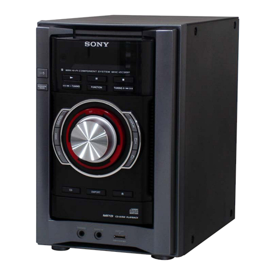
• HCD-EC98P is the amplifi er, CD player and
tuner section in MHC-EC98P/EC98Pi.
Main unit
AUDIO POWER SPECIFICATIONS
POWER OUTPUT AND TOTAL HARMONIC DISTORTION:
Low channel
With 8 ohm loads, both channels driven, from 120 – 10,000 Hz; 60 watts
per channel minimum RMS power, with no more than 0.7% total
harmonic distortion from 250 milliwatts to rated output.
High channel
With 8 ohm loads, both channels driven, from 2,000 – 13,000 Hz;
60 watts per channel minimum RMS power, with no more than 0.7%
total harmonic distortion from 250 milliwatts to rated output.
section
US and Canadian models:
Front Speaker
RMS output power (reference):
Low channel
95 W + 95 W (per channel at 8 Ω, 1 kHz, 10% THD)
High channel
95 W + 95 W (per channel at 8 Ω, 8 kHz, 10% THD)
Subwoofer
RMS output power (reference):
150 W (at 4 Ω, 80 Hz, 10% THD)
Australian model:
Front Speaker
Power output (rated):
Low channel
55 W + 55 W (at 8 Ω, 1 kHz, 1% THD)
High channel
55 W + 55 W (at 8 Ω, 8 kHz, 1% THD)
RMS output power (reference):
Low channel
75 W + 75 W (per channel at 8 Ω, 1 kHz, 10% THD)
High channel
75 W + 75 W (per channel at 8 Ω, 8 kHz, 10% THD)
Subwoofer
RMS output power (reference):
130 W (at 4 Ω, 80 Hz, 10% THD)
Sony Corporation
9-889-068-01
2008D05-1
Audio Business Group
©
2008.04
Published by Sony Techno Create Corporation
HCD-EC98P
Model Name Using Similar Mechanism
Mechanism Type
Base Unit Name
Optical Pick-up Block Name
SPECIFICATIONS
Inputs
AUDIO IN (stereo mini jack): Sensitivity 800 mV, impedance
22 kilohms
Outputs
PHONES (stereo mini jack): Accepts headphones with an impedance
of 8 Ω or more
SPEAKER: impedance: 8 Ω
SUBWOOFER OUT: impedance 4 Ω
CD player section
System: Compact disc and digital audio system
=770 − 810 nm)
λ
Laser: Semiconductor laser (
Emission duration: continuous
Frequency response: 20 Hz − 20 kHz
Signal-to-noise ratio: More than 90 dB
Dynamic range: More than 88 dB
Tuner section
FM stereo, FM/AM superheterodyne tuner
Antenna:
FM lead antenna
AM loop antenna
FM tuner section:
Tuning range
North American model: 87.5 − 108.0 MHz (100 kHz step)
Australian model: 87.5 − 108.0 MHz (50 kHz step)
Intermediate frequency: 10.7 MHz
AM tuner section:
Tuning range
North American model:
530 − 1,710 kHz (with 10 kHz tuning interval)
531 − 1,710 kHz (with 9 kHz tuning interval)
Australian model:
531 − 1,710 kHz (with 9 kHz tuning interval)
530 − 1,710 kHz (with 10 kHz tuning interval)
Intermediate frequency: 450 kHz
Canadian Model
Australian Model
CDM77B-K6BD90-WOD
HCD-EC78P
CDM88A-K6BD90-WOD
HCD-EC68
US, Canadian
CDM77B-K6BD90-WOD
Australian
CDM88A-K6BD90-WOD
BU-K6BD90-WOD
KSM-213DCP
General
Power requirements:
North American model: AC 120 V, 60 Hz
Australian model: AC 230 − 240 V, 50/60 Hz
Power consumption:
US model: 270 W
Canadian model: 350 VA
Australian model: 220 W
Dimensions (w/h/d) (excl. speakers):
Approx. 200 × 306 × 430 mm
Mass (excl. speakers):
US and Canadian models:
Approx. 6.9 kg
Australian model:
Approx. 7.0 kg
COMPACT DISC RECEIVER
US Model
Advertisement
Table of Contents

Related Manuals for Sony HCD-EC98P


Summary of Contents for Sony HCD-EC98P
-
Page 1: Specifications
HCD-EC98P SERVICE MANUAL US Model Canadian Model Ver. 1.0 2008.04 Australian Model • HCD-EC98P is the amplifi er, CD player and tuner section in MHC-EC98P/EC98Pi. CDM77B-K6BD90-WOD HCD-EC78P Model Name Using Similar Mechanism CDM88A-K6BD90-WOD HCD-EC68 US, Canadian CDM77B-K6BD90-WOD Mechanism Type Australian... - Page 2 LES DIAGRAMMES SCHÉMATIQUES ET LA LISTE DES PIÈCES SONT CRITIQUES POUR LA SÉCURITÉ DE FONC- TIONNEMENT. NE REMPLACER CES COM- POSANTS QUE PAR DES PIÈCES SONY DONT LES NUMÉROS SONT DON- NÉS DANS CE MANUEL OU DANS LES SUPPLÉMENTS PUBLIÉS PAR SONY.
-
Page 3: Table Of Contents
HCD-EC98P SECTION 1 SERVICING NOTES TABLE OF CONTENTS NOTES ON HANDLING THE OPTICAL PICK-UP BLOCK OR BASE UNIT SERVICING NOTES ..........The laser diode in the optical pick-up block may suffer electrostat- GENERAL ic break-down because of the potential difference generated by the .............. - Page 4 HCD-EC98P HOW TO OPEN THE TRAY WHEN POWER SWITCH TURN OFF Pull the tray by the hand. (Australian) lever (US, Canadian) boss gear Turn a gear by a driver till a lever falls down to the position of the figure.
- Page 5 HCD-EC98P CAPACITOR DISCHARGE FOR ELECTRIC SHOCK PREVENTION In checking the MAIN board, make a capacitor discharge of C622 and C626 for electric shock prevention. 800 Ω/2W MAIN board C626 C622 MAIN board 800 Ω/2W MODEL IDENTIFICATION – Back Panel –...
-
Page 6: General
HCD-EC98P SECTION 2 This section is extracted GENERAL from instruction manual. US and Canadian models: Basic Operations Adjusting the sound Listening to the radio Using optional audio components Select “TUNER FM” or “TUNER AM. ” To adjust the volume To connect an optional headphones Press FUNCTION +/−... - Page 7 Use buttons on the remote to create your own program. Press DISPLAY to display the clock. If the issue persists, contact your nearest Sony dealer. Press FUNCTION +/− repeatedly to select the CD the clock is not set. ...
-
Page 8: Basic Operations
HCD-EC98P Australian model: Basic Operations Adjusting the sound Listening to the radio Using optional audio components Select “TUNER FM” or “TUNER AM. ” To adjust the volume To connect an optional headphones Press FUNCTION +/− (or FUNCTION on the unit) Press VOLUME +/−... - Page 9 Use buttons on the remote to create your own program. Press DISPLAY to display the clock. If the issue persists, contact your nearest Sony dealer. the clock is not set. Press FUNCTION +/− (or FUNCTION on the unit) ...
-
Page 10: Disassembly
HCD-EC98P SECTION 3 DISASSEMBLY • This set can be disassembled in the order shown below. 3-1. DISASSEMBLY FLOW 3-2. SIDE PANEL (L)/(R) (Page 11) 3-3. PANEL (TOP) (Page 11) 3-7. BACK PANEL 3-5. FRONT PANEL 3-4. MAIN BOARD 3-6. FRONT PANEL BLOCK... -
Page 11: Side Panel (L)/(R)
HCD-EC98P Note: Follow the disassembly procedure in the numerical order shown below. 3-2. SIDE PANEL (L)/(R) two screws (BVTP3 × 10) two screws (BVTP3 × 10) four screws (case3 TP) side panel (L) side panel (R) four screws (case3 TP) 3-3. -
Page 12: Main Board
HCD-EC98P 3-4. MAIN BOARD (US, Canadian) connector (CN151) fan connector (CN701) MAIN board flexible flat cable (7 core) two screws (CN643) (BVTP3 × 6) flexible flat cable (5 core) (CN602) connector (CN633) fan connector (CN601) five screws (BVTP3 × 10) screw (BVTP3 ×... -
Page 13: Front Panel Block (Us And Canadian Models)
HCD-EC98P 3-6. FRONT PANEL BLOCK (US and Canadian models) flexible flat cable (11 core) (CN609) flexible flat cable (31 core) (CN803) front panel block boss flexible flat cable bottom side (9 core) (CN605) pull the tray by hand. Slide the boss by a driver. -
Page 14: Cd Mechanism Block (Australian Model)
HCD-EC98P 3-8. 3 CD MECHANISM BLOCK (Australian model) flexible flat cable (21 core) (MAIN board: CN608/ CD board: CN201) 3 CD mechanism block four screws flexible flat cable (BVTP3 × 10) (13 core) two tapes Note: When installing the CD mechanism section, install two tapes for prevention of noise. -
Page 15: Cd Mechanism Block (Us And Canadian Models)
HCD-EC98P 3-10. 1 CD MECHANISM BLOCK (US and Canadian models) PT block connector (power cord) two screws (CN053) (BVTP4 × 12) three screws flexible flat cable (BVTP3 × 10) (21 core) (CN201) two screws (BVTP4 × 12) 1 CD mechanism block... -
Page 16: Belt (Us And Canadian Models)
HCD-EC98P 3-12. BELT (US and Canadian models) position of belt belt belt claw claw tray (AU) 3-13. BELT (Australian model) position of belt belt cover belt four screws two belts (DLM3A) -
Page 17: Op Base Assy (Ksm-213D)
HCD-EC98P 3-14. OP BASE ASSY (KSM-213D) op base assy (KSM-213D) flexible flat cable (16 core) (CN301) CD board Remove four solders. -
Page 18: Test Mode
HCD-EC98P SECTION 4 TEST MODE COLD RESET CD TRAY LOCK The cold reset clears all data including preset data stored in the This mode is for the antitheft of CD disc in shop. (not for trans- memory to initial conditions. Execute this mode when returning port) the set to the customer. - Page 19 HCD-EC98P [CD SERVO TEST MODE] CD Servo Test Mode Tree: Higher layer Lower layer of menu hierarchy This mode can check the servo system operations of the optical S Curve Mode LD ON pick-up system (= optical unit + CD board).
- Page 20 HCD-EC98P CD SERVICE MODE Contents of “CDM Errors” Error display example This mode can move the SLED of the optical pick-up, and also can M 0 FF 11 42 turn the optical pick-up laser power on and off. Procedure: 1 2 3 4 1.
- Page 21 HCD-EC98P Key Operation: 3 It indicates the on-going processing of optical pick-up system [DISPLAY]: (= optical unit + BD board) when the trouble has occurred. The display changes in the following order when- 01: The CD SHIP mode processing is in progress.
-
Page 22: Electrical Adjustments
HCD-EC98P SECTION 5 ELECTRICAL ADJUSTMENTS 0 dB = 1 μV CD SECTION TUNER SECTION [AM] Note: Setting: 1. CD Block is basically constructed to operate without adjustment. FUNCTION: AM 2. Use YEDS-18 disc (3-702-101-01) unless otherwise indicated. 3. Use an oscilloscope with more than 10 MΩ impedance. - Page 23 HCD-EC98P FM AUTO STOP CHECK AM FREQUENCY COVERAGE ADJUSTMENT Reading on Digital Adjustment Part Frequency Display generator Voltmeter L801 530 kHz 1.5 ± 0.1 V Confi rmation 1,710 kHz 8 ± 0.5 V 75 Ω AM TRACKING ADJUSTMENT Adjust for a maximum reading on level meter...
- Page 24 HCD-EC98P Adjustment Location and Connecting Points: – MAIN Board (Component Side) – L801 FM Frequency L804 Coverage Adjustment AM Tracking Adjustment L802 FM Detector Adjustment L803 FM Frequency Coverage Adjustment L805 AM Tracking Adjustment – MAIN Board (Conductor Side) –...
-
Page 25: Diagrams
HCD-EC98P SECTION 6 DIAGRAMS 6-1. BLOCK DIAGRAM - CD SERVO, TUNER Section - CN801 ANTENNA FM/AM BAND-PASS FILTER 36 FM RF-IN FM-MIX 8 FM IF-IN FM DET-OUT 22 MPX-IN L-OUT TUNER-L FL803 R-OUT R-CH L805 T801 TRACKING AM IF CF801... -
Page 26: Block Diagram - Main Section
HCD-EC98P 6-2. BLOCK DIAGRAM - MAIN Section - J492 R-CH TB603 PHONES SUBWOOFER IMPEDANCE: – USE 4Ω INPUT SELECTOR, RY701 ELECTRICAL VOLUME IC602 POWER TB602 RY602 IC101 TUNER-L TUNER-L OUT-L SPEAKER – LOW FREQ. IMPEDANCE: R-CH USE 8Ω – CD-L... - Page 27 HCD-EC98P THIS NOTE IS COMMON FOR PRINTED WIRING BOARDS AND SCHEMATIC DIAGRAMS. • Circuit Boards Location (In addition to this, the necessary note is printed in each block.) MAIN board For Printed Wiring Boards. For Schematic Diagrams. Note: Note: • X : Parts extracted from the component side.
-
Page 28: Printed Wiring Board - Cd Board
HCD-EC98P 6-3. PRINTED WIRING BOARD - CD Board - • See page 27 for Circuit Boards Location. • : Uses unleaded solder. CD BOARD (CONDUCTOR SIDE) CD BOARD (COMPONENT SIDE) M401 (SPINDLE) S201 (LIMIT) C404 C403 R402 IC401 TP124 M402... -
Page 29: Schematic Diagram - Cd Board
HCD-EC98P 6-4. SCHEMATIC DIAGRAM - CD Board - • See page 40 for waveforms. • See page 40 for IC Block Diagrams. • See page 43 for IC Pin Function Description. (BX5BT/CBX1) R127 R126 C107 C136 R125 R120 R142 R139... -
Page 30: Printed Wiring Boards - Main Section
HCD-EC98P 6-5. PRINTED WIRING BOARDS - MAIN Section - • See page 27 for Circuit Boards Location. • : Uses unleaded solder. • Semiconductor Location Ref. No. Location (US, CND) M701 M601 D601 (FAN) (FAN) HI AMP LOW AMP BOARD... -
Page 31: Schematic Diagram - Main Section (1/3)
HCD-EC98P 6-6. SCHEMATIC DIAGRAM - MAIN Section (1/3) - ∗Q601 ∗R724-726 MAIN BOARD (1/3) Q603, 607 Q601, 602 KTA1266 (AUS) 4.7 (US, CND) PROTECT DETECT FAN MOTOR DRIVE KTA1273 (US, CND) 15 (AUS) CN601 Q601 (US, CND) R726 R725 R724... -
Page 32: Schematic Diagram - Main Section (2/3)
HCD-EC98P 6-7. SCHEMATIC DIAGRAM - MAIN Section (2/3) - • See page 40 for IC Block Diagrams. MAIN BOARD (2/3) D631 R687 MA2J1110GLS0 CD-AVR I-P-MONI MAIN D617 BOARD MC2838-T112-1 (3/3) (Page 33) R685 R693 4.7k O-POWER W609 MAIN BOARD (1/3) -
Page 33: Schematic Diagram - Main Section (3/3)
HCD-EC98P 6-8. SCHEMATIC DIAGRAM - MAIN Section (3/3) - • See page 40 for waveforms. • See page 40 for IC Block Diagrams. (3/3) MAIN BOARD L801 D801 AM FREQUENCY C819 SVC347A-TL-E COVERAGE 470p C835 C836 C837 JW801 JW802 0.047 0.022... -
Page 34: Printed Wiring Board - Hi Amp Board
HCD-EC98P 6-9. PRINTED WIRING BOARD - HI AMP Board - • See page 27 for Circuit Boards Location. • : Uses unleaded solder. HI AMP BOARD JW157 JW151 D152 JW154 R164 C159 C160 C170 R163 R161 CN152 R185 Q152 C169... -
Page 35: Printed Wiring Board - Low Amp Board
HCD-EC98P 6-11. PRINTED WIRING BOARD - LOW AMP Board - • See page 27 for Circuit Boards Location. • : Uses unleaded solder. • Semiconductor Location Ref. No. Location D101 D102 D103 LOW AMP BOARD IC101 Q101 Q102 Q103 D103... -
Page 36: Printed Wiring Board - Panel Board
HCD-EC98P 6-13. PRINTED WIRING BOARD - PANEL Board - • See page 27 for Circuit Boards Location. • : Uses unleaded solder. • Semiconductor Location Ref. No. Location D301 PANEL BOARD D302 D303 D304 SW303 - 305, SW311 - 319... -
Page 37: Schematic Diagram - Panel Board
HCD-EC98P 6-14. SCHEMATIC DIAGRAM - PANEL Board - • See page 40 for waveforms. • See page 40 for IC Block Diagrams. • See page 43 for IC Pin Function Description. PANEL BOARD LCD301 LIQUID CRYSTAL DISPLAY CN301 TP301 R301... -
Page 38: Printed Wiring Boards - Key Section
HCD-EC98P 6-15. PRINTED WIRING BOARDS - KEY Section - 6-16. SCHEMATIC DIAGRAM - KEY Section - • See page 27 for Circuit Boards Location. • : Uses unleaded solder. KEY CD BOARD SW301, 302, SW306 - 310 W403 (AUS) R411... -
Page 39: Printed Wiring Board - Pt Board
HCD-EC98P 6-17. PRINTED WIRING BOARD - PT Board - • : Uses unleaded solder. • See page 27 for Circuit Boards Location. 6-18. SCHEMATIC DIAGRAM - PT Board - PT BOARD PT BOARD C051 PT005 RY001 SUB POWER PT005 SUB POWER TRANSFORMER... -
Page 40: Printed Wiring Board - Motor Board (Us And Canadian Models)
HCD-EC98P 6-19. PRINTED WIRING BOARD - MOTOR Board (US, Canadian models) - • Waveforms • See page 27 for Circuit Boards Location. • : Uses unleaded solder. – CD Board – – MAIN Board – – PANEL Board – IC101... - Page 41 HCD-EC98P – MAIN Board – IC701 BD9701CP-V5 IC602 BD3499FV-E2 REGULATOR STANDBY 28 FIL INPUT INPUT 27 GND GAIN SELECTOR VOLTAGE REFERENCE PC BUS 26 SDA LOGIC 25 SCL 2 3 4 5 SEL2 INVERTER SEL1 24 VCC VOL1 VOLUME VOL2...
- Page 42 HCD-EC98P IC801 LV23003VA 36 FM RF-IN AM RF-IN 35 GND2 34 FMRF-OUT 33 VCC2 FM-MIX 32 FM-OSC GND1 AM-MIX 31 AM-OSC VCC1 30 BO2 29 BO1 BUFFER LOW-PASS 28 LP-OUT FILTER 27 LP-IN 26 PD 25 AGC AMIF-IN 24 AMDET-OUT...
- Page 43 HCD-EC98P • IC Pin Function Description CD BOARD IC101 TC94A70FG-006 (D, HZ (CD-MP3 PROCESSOR) Pin No. Pin Name Description AVSS3 Ground terminal RFZi RF ripple zero crossing signal input terminal RFRP RF ripple signal output terminal SBAD/RFDC Sub beam addition signal or RF peak detection signal output terminal...
- Page 44 HCD-EC98P Pin No. Pin Name Description DOUT (PO6) Digital audio data output terminal Not used AOUT (PO7) Audio data output terminal Not used BCK (PO8) Bit clock signal output terminal Not used LRCK (PO9) L/R sampling clock signal output terminal...
- Page 45 HCD-EC98P PANEL BOARD IC301 MB90F831PF-G-SPE1 (SYSTEM CONTROLLER) Pin No. Pin Name Description SEG32 Segment drive signal output to the liquid crystal display O-AMP-ON Relay drive signal output terminal (for speaker) O-POWER Main power on/off control signal output terminal "H": on...
- Page 46 HCD-EC98P Pin No. Pin Name Description O-TU-DI Serial data output to the FM/AM DET Terminal for doubler circuit capacitor connection to develop liquid crystal display drive volt- VLCD COM0, COM1, CMO2, 59 to 62 Common drive signal output to the liquid crystal display...
-
Page 47: Exploded Views
HCD-EC98P SECTION 7 EXPLODED VIEWS Note: • -XX and -X mean standardized parts, so • Color Indication of Appearance Parts Ex- The components identifi ed by mark 0 they may have some difference from the ample: or dotted line with mark 0 are critical for original one. -
Page 48: Front Panel Section
HCD-EC98P 7-2. FRONT PANEL SECTION not supplied (KEY POWER board) not supplied supplied not supplied not supplied (KEY CD board) not supplied (JACK HOLD board) not supplied (JACK board) DMP board Ref. No. Part No. Description Remark Ref. No. Part No. -
Page 49: Chassis Section
HCD-EC98P 7-3. CHASSIS SECTION main section M601 not supplied not supplied (AC HOLD board) not supplied 3 CD mechanism section not supplied 1 CD mechanism section (US, CND) (AUS) Ref. No. Part No. Description Remark Ref. No. Part No. Description... -
Page 50: Main Section
HCD-EC98P 7-4. MAIN SECTION not supplied not supplied not supplied (HI AMP board) not supplied (REG board) not supplied (US, CND) M701 not supplied (LOW AMP board) not supplied PT006 not supplied not supplied (PT board) not supplied (HOLD board) -
Page 51: Cd Mechanism Section (Australian Model) (Cdm88A-K6Bd90-Wod)
HCD-EC98P 7-5. 3 CD MECHANISM SECTION (Australian model) (CDM88A-K6BD90-WOD) not supplied (including sled motor (M402), spindle motor (M401)) not supplied sled motor (M402) spindle motor (M401) S201 Ref. No. Part No. Description Remark Ref. No. Part No. Description Remark 1-797-193-12... -
Page 52: Cd Mechanism Section (Us And Canadian Models) (Cdm77B-K6Bd90-Wod)
HCD-EC98P 7-6. 1 CD MECHANISM SECTION (US and Canadian models) (CDM77B-K6BD90-WOD) not supplied not supplied (MOTOR board) not supplied (including sled motor (M402), spindle motor (M401)) spindle motor (M401) sled motor (M402) S201 Ref. No. Part No. Description Remark Ref. No. -
Page 53: Electrical Parts List
HCD-EC98P SECTION 8 ELECTRICAL PARTS LIST Note: • Due to standardization, replacements in • RESISTORS When indicating parts by reference num- the parts list may be different from the All resistors are in ohms. ber, please include the board name. - Page 54 HCD-EC98P HI AMP Ref. No. Part No. Description Remark Ref. No. Part No. Description Remark R113 1-216-833-11 METAL CHIP 1/10W < VIBRATOR > R114 1-216-833-11 METAL CHIP 1/10W X102 1-795-101-21 VIBRATOR, CERAMIC (16.9344MHz) R118 1-216-845-11 METAL CHIP 100K 1/10W ************************************************************...
- Page 55 HCD-EC98P HI AMP JACK KEY CD KEY POWER LOW AMP Ref. No. Part No. Description Remark Ref. No. Part No. Description Remark < JUMPER RESISTOR > KEY CD BOARD ************* JR151 1-216-864-11 SHORT CHIP < RESISTOR > < TRANSISTOR >...
- Page 56 HCD-EC98P LOW AMP MAIN Ref. No. Part No. Description Remark Ref. No. Part No. Description Remark C124 1-165-621-91 CERAMIC CHIP 0.1uF R133 1-216-837-11 METAL CHIP 1/10W C125 1-100-566-91 CERAMIC CHIP 0.1uF R134 1-216-837-11 METAL CHIP 1/10W C126 1-100-566-91 CERAMIC CHIP 0.1uF...
- Page 57 HCD-EC98P MAIN Ref. No. Part No. Description Remark Ref. No. Part No. Description Remark C639 1-162-966-11 CERAMIC CHIP 0.0022uF C707 1-126-960-11 ELECT C640 1-162-966-11 CERAMIC CHIP 0.0022uF C709 1-137-190-91 FILM 0.22uF C641 1-126-962-11 ELECT 3.3uF C710 1-137-190-91 FILM 0.22uF C711...
- Page 58 HCD-EC98P MAIN Ref. No. Part No. Description Remark Ref. No. Part No. Description Remark D802 8-719-062-51 DIODE 1PS226-115 C844 1-100-566-91 CERAMIC CHIP 0.1uF D803 6-501-369-01 DIODE SVC230-TB-E C845 1-115-467-11 CERAMIC CHIP 0.22uF C846 1-162-970-11 CERAMIC CHIP 0.01uF D804 6-501-369-01 DIODE SVC230-TB-E...
- Page 59 HCD-EC98P MAIN Ref. No. Part No. Description Remark Ref. No. Part No. Description Remark Q605 8-729-120-28 TRANSISTOR 2SC1623-L5L6 R638 1-249-403-11 CARBON 1/4W Q606 8-729-120-28 TRANSISTOR 2SC1623-L5L6 R639 1-216-845-11 METAL CHIP 100K 1/10W Q607 8-729-120-28 TRANSISTOR 2SC1623-L5L6 (US, CND) R640 1-216-845-11...
- Page 60 HCD-EC98P MAIN Ref. No. Part No. Description Remark Ref. No. Part No. Description Remark R765 1-249-389-11 CARBON 1/4W R714 1-216-841-11 METAL CHIP 1/10W (US, CND) R715 1-216-809-11 METAL CHIP 1/10W R766 1-216-833-11 METAL CHIP 1/10W R716 1-216-821-11 METAL CHIP 1/10W...
- Page 61 HCD-EC98P MAIN MOTOR PANEL Ref. No. Part No. Description Remark Ref. No. Part No. Description Remark R836 1-218-867-11 METAL CHIP 6.8K 0.5% 1/10W C311 1-164-156-11 CERAMIC CHIP 0.1uF 25V (AUS) R837 1-216-845-11 METAL CHIP 100K 1/10W R838 1-216-837-11 METAL CHIP...
- Page 62 HCD-EC98P PANEL Ref. No. Part No. Description Remark Ref. No. Part No. Description Remark < JUMPER RESISTOR > R319 1-216-809-11 METAL CHIP 1/10W R320 1-216-809-11 METAL CHIP 1/10W JR301 1-216-864-11 SHORT CHIP JR302 1-216-864-11 SHORT CHIP R321 1-216-809-11 METAL CHIP...
- Page 63 HCD-EC98P PANEL Ref. No. Part No. Description Remark Ref. No. Part No. Description Remark R360 1-216-821-11 METAL CHIP 1/10W R421 1-216-833-11 METAL CHIP 1/10W (AUS) (AUS) R422 1-216-829-11 METAL CHIP 4.7K 1/10W R361 1-216-841-11 METAL CHIP 1/10W R424 1-216-841-11 METAL CHIP...
- Page 64 HCD-EC98P Ref. No. Part No. Description Remark Ref. No. Part No. Description Remark D052 6-500-335-01 DIODE MC2838-T112-1 D055 6-500-335-01 DIODE MC2838-T112-1 < RELAY > 0 RY001 1-755-334-11 RELAY, AC POWER < TRANSFORMER > 0 PT005 1-443-846-11 TRANSFORMER, POWER (US, CND)
- Page 65 HCD-EC98P MEMO...
- Page 66 HCD-EC98P REVISION HISTORY Checking the version allows you to jump to the revised page. Also, clicking the version at the top of the revised page allows you to jump to the next revised page. Ver. Date Description of Revision 2008.04...