Pioneer DVR-7000 Service Manual
Hide thumbs
Also See for DVR-7000:
- Operating instructions manual (105 pages) ,
- Supplementary manual (1 page) ,
- Operating instruction (142 pages)
Table of Contents
Advertisement
DVD RECORDER
DVR-7000
THIS MANUAL IS APPLICABLE TO THE FOLLOWING MODEL
Model
Type
DVR-7000
KU/CA
CONTENTS
1. SAFETY INFORMATION ........................................ 2
2. ADJUSTMENT ........................................................ 4
PIONEER CORPORATION
PIONEER ELECTRONICS (USA) INC. P.O. Box 1760, Long Beach, CA 90801-1760, U.S.A.
PIONEER EUROPE NV Haven 1087, Keetberglaan 1, 9120 Melsele, Belgium
PIONEER ELECTRONICS ASIACENTRE PTE. LTD. 253 Alexandra Road, #04-01, Singapore 159936
PIONEER CORPORATION 2001
Power Requirement
AC120V
4-1, Meguro 1-chome, Meguro-ku, Tokyo 153-8654, Japan
PureCinema Progressive
2
FL OFF
DIGITAL
Î
STANDBY/ON
FL DIMMER
OPEN/CLOSE
DISCNAVI
OPEN
7
Region No.
1
3. GENERAL INFORMATION ................................... 8
3.1 DIAGNOSIS .................................................... 8
3.1.3 DEBUGGING MENU ............................. 11
3.1.4 SERVICE MODE ................................... 17
3.1.5 POWER ON SEQUENCE ..................... 18
3.1.6 DISASSEMBLY ..................................... 19
3.2 OUTLINE OF THE PRODUCT ..................... 22
DVD RECORDER
DVR-7000
SMART JOG
DVD
TIMER
AUTO REC
0
FUNCTION
3
8
STOP
PLAY
PAUSE
REC
Remarks
Advertisement
Table of Contents

Related Manuals for Pioneer DVR-7000


Summary of Contents for Pioneer DVR-7000
-
Page 1: Table Of Contents
PIONEER CORPORATION 4-1, Meguro 1-chome, Meguro-ku, Tokyo 153-8654, Japan PIONEER ELECTRONICS (USA) INC. P.O. Box 1760, Long Beach, CA 90801-1760, U.S.A. PIONEER EUROPE NV Haven 1087, Keetberglaan 1, 9120 Melsele, Belgium PIONEER ELECTRONICS ASIACENTRE PTE. LTD. 253 Alexandra Road, #04-01, Singapore 159936... -
Page 2: Safety Information
Leakage The use of a substitute replacement component which does 0.5mA current Device not have the same safety characteristics as the PIONEER tester under recommended replacement one, shown in the parts list in test this Service Manual, may create shock, fire, or other hazards. - Page 3 DVR-7000 IMPORTANT THIS PIONNER APPARATUS CONTAINS WARNING! LASER OF CLASS 1. DEVICE INCLUDES LASER DIODE WHICH SERVICING OPERATION OF THE APPARATUS EMITS INVISIBLE INFRARED RADIATION SHOULD BE DONE BY A SPECIALLY WHICH IS DANGEROUS TO EYES. THERE IS INSTRUCTED PERSON.
-
Page 4: Adjustment
DVR-7000 2. ADJUSTMENT 2.1 3D Y/C ASSY ADJUSTMENT Adjustment Name Adj. Point Measurement Point Adjustment Value Adjustment State Y/C input level adjustment TUMJ ASSY Input a white 100%(1.0Vp-p) signal into 2.00Vp-p ± 80mV VR3301 (Input system adjustment) CN3001 Pin10(SEL Y) Input 1 (composite). - Page 5 DVR-7000 2.2.2 AUDIO DEMULTIPLEX ADJUSTMENT MODE This section describes how to set the each parameter of US Audio Multiplex Decoder IC (CXA2094Q) on the TUMJ ASSY and memorize the data on the EEPROM in the TUMJ ASSY. The adjustable parameters and setting data are following : •...
- Page 6 DVR-7000 3D Y/C ASSY SIDE A VR3301 TUMJ ASSY SIDE A VR4101 IC4601 CN3001 VR1312 VR1311 VR1313 Fig1. Adjustment Point...
-
Page 7: Main Assy Adjustment
DVR-7000 2.3 MAIN ASSY ADJUSTMENT Note : Use disc : [ DVD test disc GGV1025] Adjustment Name Adj. Point Measurement Point Adjustment Value Adjustment State MAIN ASSY Master clock free-running adjustment 27.000000MHZ No input signal or during test disc play-... -
Page 8: General Information
Setting the Model type and Region No. for DVD Recorder For the DVD recorder DVR-7000/KU/CA and /LB type, it is necessary to set the region No. [1 or 3] on the FLASH ROM in the MAIN ASSY and the model type [KU or LB] on the EEPROM in the TUMJ ASSY. So when the MAIN ASSY or TUMJ ASSY is renewed, "The Model type and Region setting mode screen"... -
Page 9: Cprm Id Number And Id Data Setting
DVR-7000 3.1.2 CPRM ID NUMBER AND ID DATA SETTING Use ID DATA DISC [GGV1065] and Service Remote Control Unit [GGF1067] Entering the ID Number and ID Data for DVD Recorder For the DVD recorder,it is necessary with the recoding/playback of DVD–RW disc to set an individual number (ID number) and ID data to each recorder. - Page 10 DVR-7000 When the ID data have been read, the data are written to the When the ID data have been written to the FLASH-ROM, the FLASH-ROM. message "Rom Write OK" is displayed on the screen. (The FL display indicates "WRITE ID DATA.") (The FL display indicates "ID DATA OK.")
-
Page 11: Debugging Menu
[DISP] key. Description of Each Mode 1. Mode Menu 1 [Version information, etc.] Subscreen 1 1 DVR-7000 /KU SYSCON RELEASE_1 1 2 OK: Correct combination R e v : 1. 6 1 0 9. 2. 2 2 6. 2. 4... - Page 12 DVR-7000 2. Mode Menu 2 [VR playback (related to decoding), debug display] Subscreen 1 (This menu is for design use.) Subscreen 2 Error history of VR playback 1 G : 0 1–0 1 0 0 m 0 0 s 0 0 # –. – e – –...
- Page 13 DVR-7000 3. Mode Menu 3 [iLink-related debug display] Subscreen 1 1 [R e c o r d e r] G U I D : X X X X X X X X X X X X X X BGC : X X X X...
- Page 14 DVR-7000 7. Mode Menu 7 [VR playback-related debug information] Subscreen 1– 3 1 G01 – 01 E p 0 1 0 0 : 2 0 ' 1 3 " 0 0 V r p l a y 0 0 0...
- Page 15 DVR-7000 - f i u l i h t l e l i o i t l b i l l e n i l l i a n i l u l i l a i o i t u l i Table 7.1 Description of VR playback-related errors...
- Page 16 DVR-7000 y t i d i l d i l y t i d i l d i l d i l d i l d i l t t i r e l i d i l d i l...
-
Page 17: Service Mode
DVR-7000 3.1.4 SERVICE MODE 1. Error Rate Measurement How to Enter this Mode : Press the [ESC] and [SIDE-B] buttons sequentially. Functions : When enter this mode, measure the error rate automatically. VR mode record Record it for 10 seconds and playback the title. -
Page 18: Power On Sequence
DVR-7000 3.1.5 POWER ON SEQUENCE Tuner U-com System U-com (Inital Program Loader) Connect a power cord to an AC outlet. The Tuner microcomputer starts. The system control computer starts. Initialization of peripheral circuit LSI check register, RAM, etc. Time display on the FL display FLASH check “LSI NG”... -
Page 19: Disassembly
DVR-7000 3.1.6 DISASSEMBLY × 2 Disconnect the connector Remove the bonnet. (Screw ×10) CN2009 POWER SUPPLY Open the tray. Assy Unhook STANDBY/ON OPEN/CLOSE Barrier Sheet CN204 Unhook the bottom side 4 marking parts. Unhook Remove the front panel. Disconnect the FFC and PH cable. - Page 20 DVR-7000 DRIVE UNIT Disconnect all connectors on the MAIN ASSY. ( ×7) Shield Case × 2 × 2 Fan Duct Upper Frame Clamper Holder Drive Unit Drive Unit Remove the Drive Unit. Make clean the pick-up lens.
- Page 21 DVR-7000 CAUTION FOR CABLE STYLING Bariier Sheet Do not sandwitch the DV cable with the bonnet. • Be sure to bind the cable from the POWER SUPPLY ASSY with the wire saddle. • Attach the barrier sheet. Bind the cable with the binder.
-
Page 22: Outline Of The Product
DVR-7000 3.2 OUTLINE OF THE PRODUCT 3.2.1 DVD-RW Standard As to the characteristics after recording, the reflectivity is within The DVD-RW disc is a phase-change type, rewritable disc, as are the standard value of a dual-type DVD-ROM, and the specifications CD-RW and DVD-RAM discs. - Page 23 DVR-7000 3.2.2 Video Recording Format The DVD Forum created the DVD-Video format as an application In comparison, in considering the use for general users' recording/ format. As this format was created mainly for the authoring systems playback use, such as VCR, Camcorder, and MD, the Video...
- Page 24 DVR-7000 3.2.3 Main Newly Developed Features 3.2.3.1 Pickup In addition to DVD-R/RW recording and DVD-ROM playback, the newly developed pickup can play back CD media. The laser diodes MAIN Assy are provided separately for DVD and CD, but one lens is used for IC8008 PD0272A both.
- Page 25 DVR-7000 3.2.4 System Control Structure Fig. 9 shows a system block diagram of the DVR-7000. The system is roughly divided into two blocks: the writer block (which writes in and reads out data to and from a disc), and the recorder block (which encodes/decodes video and audio signals and generally controls the whole system, including UI).
- Page 26 DVR-7000 1394 Link 1394Phy ceLynx MPEG PU&Mecha Main DDCD Video Enc. Audery & DVcodec Audio I/F DVxcel aprilia Audio (1/2) BS/UV Tuner /Line DVD-ROM Enc. Drv. George R3-chip ATA-IF H.A. A2-Chip Graphics Slalom Ouroboros Tuner/FL Engine Control CPU DVD-ROM Dec.
-
Page 27: Dvd Playback
3.2.4.2 Recording System formatting in the writer block, transferred via the ATAPI bus, and is The basic flow of data with the DVR-7000 is similar to that with the temporarily stored in the SDRAM (stream buffer) of the ATAPI DVR-2000. Recordable media are DVD-R (Ver. 2.0) and DVD- interface LSI. - Page 28 Specifications Other conventional features and specifications are as follows: The following functions and specifications are newly added to the • 96-kHz/24-bit DAC DVR-7000, compared with the DVR-2000. • 48-kHz/20-bit ADC • 3-Dimensional Y/C-separation circuit • Frame TBC 3.2.6.1 CD/Video-CD Playback •...
-
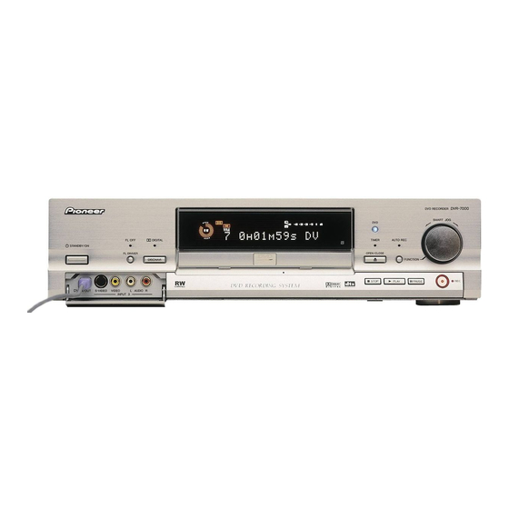
Page 29: Panel Facilities And Specifications
DVR-7000 4. PANEL FACILITIES AND SPECIFICATIONS 4.1 PANEL FACILITIES FRONT PANEL PureCinema Progressive DVR-7000 DVD RECORDER SMART JOG TIMER AUTO REC FL OFF DIGITAL Î STANDBY/ON FL DIMMER OPEN/CLOSE FUNCTION DISCNAVI OPEN STOP PLAY PAUSE KU/CA type 12 SMART JOG control... - Page 30 DVR-7000 DISPLAY RESERVED ∞ – –40 –30 –20 –10 VIDEO RW FINALIZE LOCK PLAYLIST TITLE TRACK CHP ANGLE REMAIN SAP STEREO L R Play/record indicator TITLE Outer (white) ring indicates the playback speed Display shows the current title number of the and direction.
-
Page 31: Rear Panel
DIGITAL OUT CONTROL AC IN – Power inlet CONTROL IN / OUT Use for connecting to other Pioneer components COMPONENT VIDEO OUT bearing the Pioneer Î mark. Connect the For connecting to a TV or monitor that has CONTROL OUT of one component to the component video input CONTROL IN of another using a mini-plug cord. -
Page 32: Remote Control
DVR-7000 REMOTE CONTROL STANDBY/ON Switches the recorder on/into standby STANDBY OPEN CHP MARK /CLOSE NAVI Inserts a chapter marker when playing/recording a PLAYLIST SETUP MARK MARK VR mode DVD-RW disc ERASE DISCNAVI EDIT PLAYLIST Switches beween Original and Playlist ERASE... - Page 33 DVR-7000 13 Number buttons 25 CHANNEL –/+ Changes the channel of the built-in TV tuner 14 PROGRAM (Press SHIFT first to access) Displays the program play screen 26 SEARCH MODE Allows searching of the disc by title, chapter, REPEAT (Press SHIFT first to access) track, time, etc.
- Page 34 DVR-7000 4.2 SPECIFICATIONS General Input/Output System ....DVD-Video, DVD-R/RW, Video-CD, CD VHF/UHF antanna input/output terminal ..VHF/UHF set Power requirements ....120 V, 60 Hz(for KU/CA type) 75 Ω (F-shape connector) Power requirements ...... 110 V, 60 Hz(for LB type) Video input ........