
Related Manuals for Acer Aspire 5920G Series


Summary of Contents for Acer Aspire 5920G Series
- Page 1 Aspire 5920G Series Service Guide Service guide files and updates are available on the ACER/CSD web; for more information, please refer to http://csd.acer.com.tw PRINTED IN TAIWAN...
-
Page 2: Revision History
Revision History Please refer to the table below for the updates made on Aspire Chapla service guide. Date Chapter Updates... - Page 3 Copyright Copyright © 2007 by Acer Incorporated. All rights reserved. No part of this publication may be reproduced, transmitted, transcribed, stored in a retrieval system, or translated into any language or computer language, in any form or by any means, electronic, mechanical, magnetic, optical, chemical, manual or otherwise, without the prior written permission of Acer Incorporated.
- Page 4 Conventions The following conventions are used in this manual: SCREEN MESSAGES NOTE WARNING CAUTION IMPORTANT Denotes actual messages that appear on screen. Gives bits and pieces of additional information related to the current topic. Alerts you to any damage that might result from doing or not doing specific actions.
- Page 5 DIFFERENT part number code to those given in the FRU list of this printed Service Guide. You MUST use the list provided by your regional Acer office to order FRU parts for repair and service of customer machines.
-
Page 7: System Specifications
(dual-channel support) Display and graphics 15.4” WXGA+ high-brightness Acer CrystalBrite 16 ms typical of/off and 8 ms average gray-to-gray response time Simultaneous multi-window viewing via Acer Vista ® Supporting NVIDIA Acceleration, integrated HDTV encoder) dual-link DVI, Microsoft OpenEXR High Dynamic Range (HDR) technology, Unified Shader Architecture, Geometry Instancing 2.0, SGI OpenGL... - Page 8 88/89-key keyboard with 101/102 key emulation Touchpad with 4-way scroll button Six Media keys Four easy-launch buttons Communication Acer Video Conference, featuring Voice and Video over Internet Protocol (VVoIP) support via Acer OrbiCam and optional Acer Bluetooth Acer OrbiCam 30 degree ergonomic rotation...
- Page 9 Fast infrared (FIR) port External display (VGA) port S-video/TV-out (NTSC/PAL) port Headphones/speaker/line-out port with S/PDIF support Microphone-in jack Line-in jack Ethernet (RJ-45) port Modem (RJ-11) port DC-in jack for AC adaptor 3G SIM Card slot (optional) TV-in port (optional) RF-in port (optional) Chapter 1...
- Page 10 Environment Temperature: Operating: 5ºC to 35ºC Non-operating: -20ºC to 65ºC Humidity (non-condensing): Operating: 20%~80% Non-operating: 20%~80% Chapter 1...
- Page 11 System Block Diagram Chapter 1...
-
Page 12: Board Layout
Board Layout Top View CN15 Battery Connector CPU Socket CN20 Fan Connector CN13 VGA Jack CN14 Ethernet Controller CN18 USB Connector CN19 Wireless LAN Card Connector DC-IN Connector CN25 DIMM Socket CN23 DIMM Socket North Bridge CN21 HDMI Connector CN22 S-Video Connector CN23 USB Connector... -
Page 13: Bottom View
Bottom View 20 21 LCD Connector MDC Connector Email Board Connector Power Board Connector Keyboard Connector Audio Codec DDR2 SDRAM IC Bluetooth Connector Wireless Connector Chapter 1 9 10 Winbond CN16 CN11 CN12 LED2 LED3 DDR2 SDRAM IC Card Bus Socket Touchpad Connector Subwoofer Connector MSC Connector... -
Page 14: Your Acer Notebook Tour
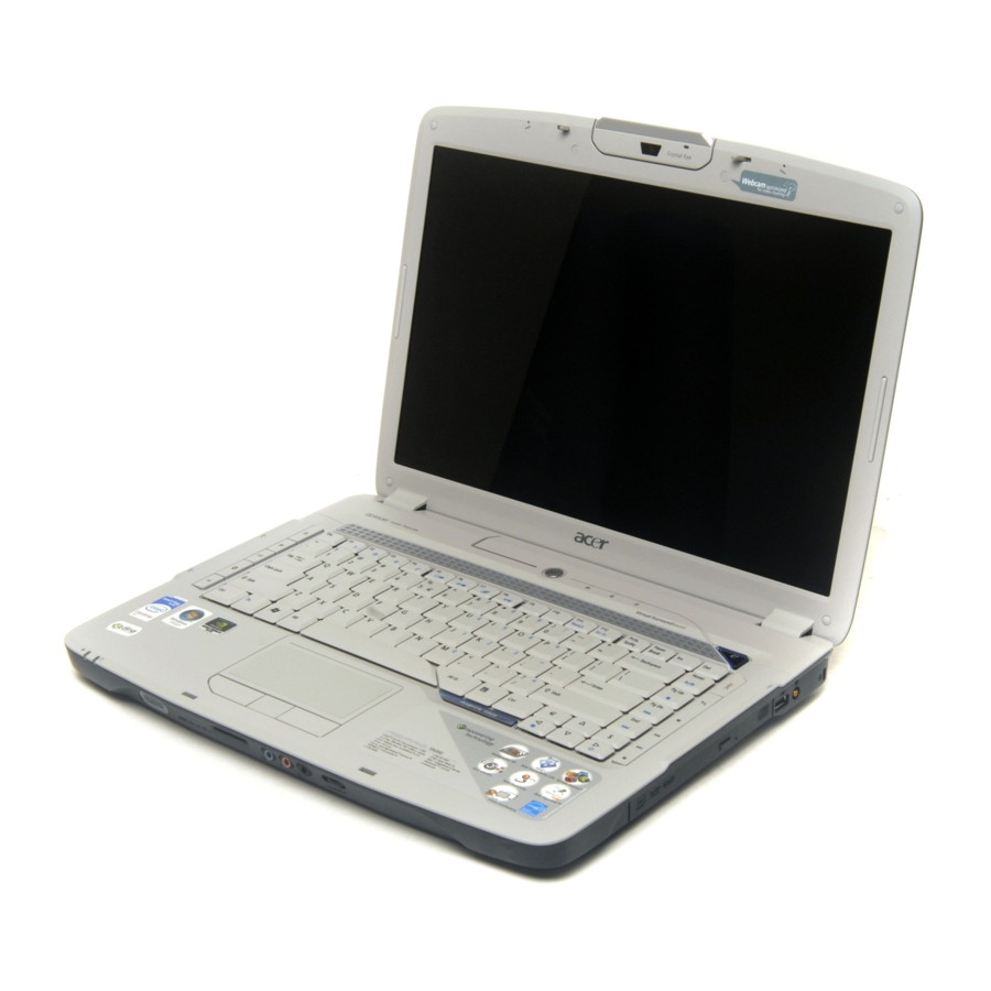
Your Acer Notebook tour After knowing your computer features, let us show you around your new Aspire computer. Front View Icon Item Built-in camera 0.3 megapixel web camera for video communication. Microphone Internal microphone for sound recording. Power button Turns the computer on and off. -
Page 15: Closed Front View
Closed Front View Icon Icon Chapter 1 Wireless communication Enables/disables the wireless function. button/indicator Indicates the status of wireless LAN communication. WWW/E-mail buttons Button to launch your internet browser and e-mail reader. ® Bluetooth Enables/disables the Bluetooth communication button/ Indicates the status of Bluetooth indicator communication. -
Page 16: Left View
Left View Icon Line-in jack Accepts audio line-in devices (e.g., audio CD player, stereo walkman). Microphone-in jack Accepts input from external microphones. Headphones/speaker/ Connects to audio line-out devices (e.g., line-out jack with S/PDIF speakers, headphones). support Volume control Increases and decreases the volume. Item External display (VGA) Connects to a display device (e.g., external... -
Page 17: Right View
Right View Icon Rear view Icon Chapter 1 Item Optical drive Internal optical drive; accepts CDs or DVDs (slot-load or tray-load depending on model). Optical disk access Lights up when the optical drive is active. indicator Optical drive eject Ejects the optical disk from the drive. button Emergency eject hole Ejects the optical drive tray when the... -
Page 18: Base View
Base view Item Battery bay Battery lock Battery release latch Ventilation slots and cooling fan System fan Memory compartment Hard disk bay Indicators The computer has several easy-to-read status indicators. The front panel indicators are visible even when the computer cover is closed up. Description Houses the computer’s battery pack. - Page 19 You can also find an Empowering Key “ Press “ “ to run the Acer Empowering Technology. The mail and Web browser buttons are pre-set to email and Internet programs, but can be reset by users. To set the Web browser, mail and programmable buttons, run the Acer Launch Manager.
-
Page 20: Touchpad Basics
NOTE: When using the touchpad, keep it - and your fingers - dry and clean. The touchpad is sensitive to finger movements; hence, the lighter the touch, the better the response. Tapping too hard will not increase the touchpad’s responsiveness. Default application Acer Empowering Technology (user-programmable) Internet browser (user-programmable) Email application (user-programmable) User-programmable... -
Page 21: Using The Keyboard
Using the Keyboard The keyboard has full-sized keys and an embedded keypad, separate cursor keys, one Windows key and twelve function keys. Lock Keys and embedded numeric keypad The keyboard has three lock keys which you can toggle on and off. Lock Key Caps Lock When Caps Lock is on, all alphabetic characters typed... -
Page 22: Hot Keys
Function Hot key help Displays help on hot keys. Acer eSettings Launches the Acer eSettings in Acer eManager. Acer ePower Launches the Acer ePower Management in Acer Management Empowering Technology. See “Acer Empowering Technology” on page 18. -
Page 23: Special Key
Hot Key Icon <Fn>+<F5> <Fn>+<F6> <Fn>+<F7> <Fn>+<F8> <Fn>+<w> <Fn>+<y> <Fn>+<-x> <Fn>+<z> Special Key You can locate the Euro symbol and US dollar sign at the upper-center of your keyboard. To type: The Euro symbol Open a text editor or word processor. Hold <Alt Gr>... -
Page 24: Acer Empowering Technology
To access this utility, either click on the “Acer eNet Management” icon on your notebook, or start the program from the Start menu. You also have the option to set Acer eNet Management to start automatically when you boot up your PC. - Page 25 Acer eNet Management can save network settings for a location to a profile, and automatically switch to the appropriate profile when you move from one location to another. Settings stored include network connection settings (IP and DNS settings, wireless AP details, etc.), as well as default printer settings.
-
Page 26: Acer Epower Management
Acer ePower Management Acer ePower Management features a straightforward user interface. To launch it, select Acer ePower Management from the Empowering Technology interface. AC Mode (Adapter mode) The default setting is “Maximum Performance.” You can adjust CPU speed, LCD brightness and other settings, or click on buttons to turn the following functions on/off: Wireless LAN, Bluetooth, CardBus, FireWire (1394), Wired LAN and Optical Device if supported. -
Page 27: Acer Epresentation Management
For additional power options, click “More Power option”. Acer ePresentation Management Acer ePresentation Management lets you project your computer’s display to an external device or project using the hot key: Fn + F5. If auto-detection hardware is implemented in the system, your system display will be automatically switched out when an external display is connected to the system. -
Page 28: Acer Edatasecurity Management
Acer eDataSecurity Management Acer eDataSecurity Management is handy file encryption utility that protects your files from being accessed by unauthorized persons. It is conveniently integrated with Windows explorer as a shell extension for quick and easy data encryption/decryption and also supports on-the-fly file encryption for MSN Messenger and Microsoft Outlook. - Page 29 Chapter 1...
-
Page 30: Acer Elock Management
Interfaces - includes serial ports, parallel port, infrared (IR), and Bluetooth. To activate Acer eLock Management, a password must be set first. Once set, you can apply locks to any of the devices. Lock(s) will immediately be set without any reboot necessary, and will remain locked after rebooting, until unlocked. -
Page 31: Acer Erecovery Management
Acer eRecovery Management Acer eRecovery Management is a powerful utility that does away with the need for recovery disks provided by the manufacturer. The Acer eRecovery Management utility occupies space in a hidden partition on your system’s HDD. User-created backups are stored on D:\ drive. Acer eRecovery Management provides you with: Password protection. -
Page 32: Acer Esettings Management
Acer eSettings Management Acer eSettings Management allows you to inspect hardware specifications and to monitor the system health status. Furthermore, Acer eSettings Management enables you to optimize your Windows operating system, so your computer runs faster, smoother and better. Acer eSettings Management also: Provides a simple graphical user interface for navigating. - Page 33 The Acer OrbiCam is automatically selected as the capture device of any instant messenger (IM) application. To use the Acer OrbiCam as a webcam, open the IM service, then select the video/webcam feature. You can now broadcast from your location to an IM partner anywhere in the world.
-
Page 34: Using The System Utilities
Acer GridVista is a handy utility that offers four pre-defined display settings so you can view multiple windows on the same screen. To access this function, please go to Start > All Programs and click on Acer GridVista. Start All Programs... - Page 35 NOTE: Please ensure that the resolution setting of the second monitor is set to the manufacturer's recommended value. Note: Note: Launch Manager Launch Manager allows you to set the four easy-launch buttons (see their locations mentioned in “Easy- "Easy-launch buttons" on page 24 Launch Buttons”).
-
Page 36: Hardware Specifications And Configurations
Hardware Specifications and Configurations Processor Item CPU type Core logic CPU package CPU core voltage CPU Fan True Value Table CPU Temperature Core 0 Core 1 BIOS Item BIOS vendor BIOS Version BIOS ROM type BIOS ROM size BIOS package Supported protocols BIOS password control NOTE: If you need to check PXE version, press F2 to enter BIOS then enable boot from LAN function. - Page 37 System Memory Item Memory controller Memory size DIMM socket number Supports memory size per socket Supports maximum memory size Supports DIMM type Supports DIMM Speed Supports DIMM voltage Supports DIMM package Memory module combinations Memory Combinations Slot 1 128MB 128MB 128MB 128MB 128MB...
- Page 38 LAN Interface Item Chipset Supports LAN protocol LAN connector type LAN connector location Features Modem Interface Item Data modem data baud rate (bps) Supports modem protocol Modem connector type Modem connector location Bluetooth Interface Item Chipset Data throughput Protocol Interface Connector type Wireless Module 802.11a/b/g/n Item...
- Page 39 Hard Disk Drive Interface Item Drive Format Disks Spindle speed 4200 RPM (RPM) Performance Specifications Buffer size 2048KB Interface ATA/ATAPI-6; ATA-6 Max. media transfer rate (disk-buffer, Mbytes/s) Data transfer 100 MB/Sec. rate Ultra DMA mode-5 (host~buffer, Mbytes/s) DC Power Requirements Voltage 5V(DC) +/- 5% tolerance...
- Page 40 Audio Interface Item Mono or Stereo Resolution Compatibility Sampling rate Internal microphone Internal speaker / Quantity Supports PnP DMA channel Supports PnP IRQ USB Port Item Chipset USB Compliancy Level OHCI Number of USB port Location Serial port function control PCMCIA Port Item PCMCIA controller...
- Page 41 Keyboard Item Total number of keypads Windows logo key Internal & external keyboard work simultaneously Battery Item Vendor & model name Battery Type Pack capacity Number of battery cell Package configuration Normal voltage Charge voltage LCD 15.4” inch Item Vendor & model name Screen Diagonal (mm) Active Area (mm) Display resolution (pixels)
- Page 42 LCD 15.4” inch Item Support Color Viewing Angle (degree) Horizontal: Right/Left Vertical: Upper/Lower ° Temperature Range( C) Operating Storage (shipping) LCD Inverter Item Vendor & model name Brightness conditions Input voltage (V) Input current (mA) Output voltage (V, rms) Output current (mA, rms) Output voltage frequency (k Hz) AC Adaptor Item...
-
Page 43: System Utilities
System BIOS Version: v0.2412 nVidia 0.84.41.00.08 VGA BIOS Version: xxxxxxxxxxxxxxxxxxxxxx Serial Number: Asset Tag Number: Produce Name: Manufacturer Name: Acer xxxxxxxxxxxxxxxxxxxxxxxxxxxxxxxx UUID: Help Select Item Exit Select Menu Chapter 2 during POST (when “Press <F2> to enter Setup” message is prompted... -
Page 44: Navigating The Bios Utility
Navigating the BIOS Utility There are six menu options: Info., Main, System Devices, Security, Boot, and Exit. Follow these instructions: To choose a menu, use the cursor left/right keys (zx). To choose a parameter, use the cursor up/down keys (wy). To change the value of a parameter, press por q. - Page 45 ATAPI Model Name : Optiarc DVD RW AD-7530A System BIOS Version: v0.2412 nVidia 0.84.41.00.08 VGA BIOS Version: xxxxxxxxxxxxxxxxxxxxxx Serial Number: Asset Tag Number: Produce Name: Manufacturer Name: Acer xxxxxxxxxxxxxxxxxxxxxxxxxxxxxxxx UUID: Help Select Item Exit Select Menu NOTE: The system information is subject to different models. Parameter CPU Type / CPU Speed This field shows the CPU type and speed of the system.
- Page 46 Main The Main screen displays a summary of your computer hardware information, and also includes basic setup parameters. It allows the user to specify standard IBM PC AT system parameters. Information Main System Time: [19:03:49] System Date : [04/25/2007] System Memory : 640 KB Extended Memory : 1022 MB...
- Page 47 The table below describes the parameters in this screen. Settings in boldface are the default and suggested parameter settings. Parameter System Time Sets the system time. The hours are displayed with 24-hour format. System Date Sets the system date. System Memory This field reports the memory size of the system.
- Page 48 Security The Security screen contains parameters that help safeguard and protect your computer from unauthorized use. Information Main Supervisor Password Is : User Password Is : Hard Disk Password Status : Set Supervisor Password Set User Password Set Hard Disk Password Password on boot : Help Select Item...
-
Page 49: Setting A Password
The table below describes the parameters in this screen. Settings in boldface are the default and suggested parameter settings. Parameter Supervisor Password is User Password is Hard Disk Password Status Set Supervisor Password Set User Password Set Hard Disk Password Password on Boot NOTE: When you are prompted to enter a password, you have three tries before the system halts. - Page 50 Removing a Password Follow these steps: Use the w and y keys to highlight the Set Supervisor Password parameter and press the e key. The Set Supervisor Password box appears: Type the current password in the Enter Current Password field and press e. Press e twice without typing anything in the Enter New Password and Confirm New Password fields.
- Page 51 If the new password and confirm new password strings do not match, the screen will display the following message. Chapter 2...
- Page 52 Boot This menu allows the user to decide the order of boot devices to load the operating system. Bootable devices includes the diskette drive in module bay, the onboard hard disk drive, and the CD-ROM in module bay. Information Main Boot priority order: 1: PCI BEV : MBA v9.4.5 Slot 0800 2: USB FDC :...
- Page 53 Exit The Exit screen contains parameters that help safeguard and protect your computer from unauthorized use. Information Main Exit Saving Changes Exit Discarding Changes Load Setup Defaults Discard Changes Save Changes Help Select Item Exit Select Menu The table below describes the parameters in this screen. Parameter Exit Saving Changes Exit System Setup and save your changes to CMOS.
-
Page 54: Bios Flash Utility
BIOS Flash Utility The BIOS flash memory update is required for the following conditions: New versions of system programs New features or options Restore a BIOS when it becomes corrupted. Use the Phlash utility to update the system BIOS flash ROM. NOTE: If you do not have a crisis recovery diskette at hand, then you should create a Crisis Recovery Diskette before you use the Phlash utility. -
Page 55: Machine Disassembly And Replacement
Machine Disassembly and Replacement This chapter contains step-by-step procedures on how to disassemble the notebook computer for maintenance and troubleshooting. To disassemble the computer, you need the following tools: Wrist grounding strap and conductive mat for preventing electrostatic discharge Small Philips screw driver Philips screwdriver Plastic flat head screw driver Tweezers... -
Page 56: General Information
General Information Before You Begin Before proceeding with the disassembly procedure, make sure that you do the following: Turn off the power to the system and all peripherals. Unplug the AC adapter and all power and signal cables from the system. Remove the battery pack. -
Page 57: Disassembly Procedure Flowchart
Disassembly Procedure Flowchart The flowchart on the succeeding page gives you a graphic representation on the entire disassembly sequence and instructs you on the components that need to be removed during servicing. For example, if you want to remove the system board, you must first remove the keyboard, then disassemble the inside assembly frame in that order. - Page 58 LCD Panel G*2 for 15.4" Wireless Antenna Set Screw List Item Description SCREW M2.5*3(NL) SCREW M2.5*6(NL) SCREW M2.5*10(NL) SCREW M2.5*15(NL) SCREW M2*2.2 SCREW M2*3(NL) SCREW M2*4 SCREW M3*4(NL) SCREW D-SUB 4#X40* 1/5-NI (NL) LCD Module LCD Bezel G*1 for 15" G*2 for 15.4"...
-
Page 59: Removing The Battery Pack
Removing the Battery Pack Unlock the battery lock (move the battery lock to the right). Slide the battery release latch then remove the battery. Chapter 3... - Page 60 Removing the HDD Modules/ODD Module/Memory/Wireless LAN Card/VGA Board/Thermal Module and the LCD Module To access the intenal laptop components, you have to first remove the back panel. Remove the nine screws fastening the back panel. Lift the back panel up as shown. Removing the HDD Module Pull out the HDD tab.
- Page 61 Remove the memory from the DIMM socket (If the notebook has two memory, then repeat this step). 10. Disconnect the main and auxiliary antenna from the wireless LAN card. 11. Remove the two screws fastening the wireless LAN card. 12. Take out the wireless LAN card from the main unit. Removing the VGA Board and Thermal Module 13.
- Page 62 16. Unscrew the four spring screws and remove the two screws fastening the thermal module. 17. Remove one screw from inside the battery compartment. 18. Lift the lower case and take out the thermal module from the main unit. Chapter 3...
- Page 63 Removing the Keyboard and LCD Module Disconnect the speaker, DC-In, and system fan cables. Turn the notebook over and gently pry up the keyboard as shown. Lift the keyboard up and towards you. Disconnect the keyboard cable from the main board and remove the keyboard from the main unit. Disconnect the media button, Bluetooth and Wireless cables.
- Page 64 Pull out the wireless LAN antennas from the cable holders as shown. 10. Remove the four screws securing the hinges. 11. Detach the LCD module from the main unit. Chapter 3...
-
Page 65: Disassembling The Main Unit
Disassembling the Main Unit Separate the Main Unit Into the Upper and the Lower Case Assembly Remove the two screws fastening the upper case assembly to the lower case assembly. Carefully detach the upper case assembly from the lower case assembly. Disassembling the Lower Case Assembly Removing the Power Board Remove the three screws fastening the power board. - Page 66 Removing the Subwoofer 10. Disconnect the subwoofer cable from the main board. 11. Remove the four screws fastening the subwoofer. 12. Remove the subwoofer. Removing the MDC Card Module 13. Disconnect the MDC card cable from the main board. 14. Remove the two screws fastening the MDC card module. 15.
- Page 67 Removing the USB Board 16. Remove the screw fastening the USB board. 17. Lift the USB board and disconnect the USB board cable. 18. Remove the USB board. Removing the CPU 19. Use a flat screwdriver to release the CPU lock (Turn counter clockwise). 20.
- Page 68 Removing the DC Cable and Jack 23. Turn over the lower case and use a flat screwdriver to gently push the DC jack upwards. 24. Turn the lower case over again and remove the DC cable and jack. Disassembling the Upper Case Assembly Removing the Email Board 25.
- Page 69 Removing the Launch Key Board 31. Remove the four screws fastening the launch key board. 32. Disconnect the launch key board cable as shown. 33. Remove the launch key board and disconnect the cable. Removing the Speaker 34. Remove the speaker cable from the upper case. 35.
-
Page 70: Disassembling The Lcd Module
Disassembling the LCD Module Remove the six screw rubbers as shown. Then remove the six screws fastening the LCD bezel. Detach the LCD bezel from the LCD module carefully. Remove the six screws holding the LCD. Detach the two inverter cable connectors from the inverter board. Disconnect the CCD cable connector from the CCD board. -
Page 71: Disassembling The External Modules
Remove the two screws fastening the right LCD bracket and detach it. 10. Disconnect the LCD cable from the LCD. 11. Detach the CMOS cable from the LCD cover and remove the CMOS module. Disassembling the External Modules Disassembling the HDD Module Remove the four screws holding the HDD (hard disk drive) case;... - Page 72 Chapter 3...
-
Page 73: Table Of Contents
Troubleshooting Use the following procedure as a guide for computer problems. NOTE: The diagnostic tests are intended to test only Acer products. Non-Acer products, prototype cards, or modified options can give false errors and invalid system responses. Obtain the failing symptoms in as much detail as possible. -
Page 74: System Check Procedures
System Check Procedures External Diskette Drive Check Do the following to isolate the problem to a controller, driver, or diskette. A write-enabled, diagnostic diskette is required. NOTE: Make sure that the diskette does not have more than one label attached to it. Multiple labels can cause damage to the drive or cause the drive to fail. -
Page 75: Memory Check
If any of these devices do not work, reconnect the cable connector and repeat the failing operation. Memory check Memory errors might stop system operations, show error messages on the screen, or hang the system. Boot from the diagnostics diskette and start the doagmpstotics program (please refer to main board). Go to the diagnostic memory in the test items. -
Page 76: Check The Power Adapter
Check the Power Adapter Unplug the power adapter cable from the computer and measure the output voltage at the plug of the power adapter cable. See the following figure: If the voltage is not correct, replace the power adapter. If the voltage is within the range, do the following: Replace the System board. -
Page 77: Check The Battery Pack
Check the Battery Pack To check the battery pack, do the following: From Software: Check out the Power Management in Control Panel In Power Meter, confirm that if the parameters shown in the screen for Current Power Source and Total Battery Power Remaining are correct. -
Page 78: Power-On Self-Test (Post) Error Message
Power-On Self-Test (POST) Error Message The POST error message index lists the error message and their possible causes. The most likely cause is listed first. NOTE: Perform the FRU replacement or actions in the sequence shown in FRU/Action column, if the FRU replacement does not solve the problem, put the original part back in the computer. -
Page 79: Error Message List
Index of Error Messages Error Code List Error Codes <No error code> <No error code> Error Message List Error Messages Failure Fixed Disk Stuck Key Keyboard error Keyboard Controller Failed Keyboard locked - Unlock key switch Monitor type does not match CMOS - Run Setup Run “Load Default Settings” in BIOS Setup Utility. Shadow RAM Failed at offset: nnnn System RAM Failed at offset: nnnn Extended RAM Failed at offset: nnnn... - Page 80 Error Message List Error Messages Real time clock error Previous boot incomplete - Default configuration used Memory size found by POST differed from CMOS Diskette drive A error Incorrect Drive A type - run SETUP System cache error - Cache disabled CPU ID: DMA Test Failed Software NMI Failed...
- Page 81 Error Message List No beep Error Messages No beep, power-on indicator turns off and LCD is blank. No beep, power-on indicator turns on and LCD is blank. No beep, power-on indicator turns on and LCD is blank. But you can see POST on an external CRT.
-
Page 82: Phoenix Bios Beep Codes
Phoenix BIOS Beep Codes Code Beeps Verify Real Mode Disable Non-Maskable Interrupt (NMI) Get CPU type Initialize system hardware Initialize chipset with initial POST values Set IN POST flag Initialize CPU registers Enable CPU cache Initialize caches to initial POST values Initialize I/O component Initialize the local bus IDE Initialize Power Management... - Page 83 Code Chapter 4 Beeps 2-1-2-3 Check ROM copyright notice Check video configuration against CMOS Initialize PCI bus and devices Initialize all video adapters in system QuietBoot start (optional) Shadow video BIOS ROM Display BIOS copyright notice Display CPU type and speed Initialize EISA board Test keyboard Set key click if enabled...
- Page 84 Code Beeps Initialize floppy controller Determine number of ATA drives (optional) Initialize hard-disk controllers Initialize local-bus hard-disk controllers Jump to UserPatch2 Build MPTABLE for multi-processor boards Install CD ROM for boot Clear huge ES segment register Fixup Multi Processor table Search for option ROMs.
- Page 85 Code Code Chapter 4 Beeps Unknown interrupt Beeps Initialize the chipset Initialize the bridge Initialize the CPU Initialize the system timer Initialize system I/O Check force recovery boot Checksum BIOS ROM Go to BIOS Set Huge Segment Initialize Multi Processor Initialize OEM special code Initialize PIC and DMA Initialize Memory type...
-
Page 86: Index Of Symptom-To-Fru Error Message
Index of Symptom-to-FRU Error Message LCD-Related Symptoms Symptom / Error LCD backlight doesn't work LCD is too dark LCD brightness cannot be adjusted LCD contrast cannot be adjusted Unreadable LCD screen Missing pels in characters Abnormal screen Wrong color displayed LCD has extra horizontal or vertical lines displayed. - Page 87 Power-Related Symptoms Symptom / Error Battery can’t be charged PCMCIA-Related Symptoms Symptom / Error System cannot detect the PC Card (PCMCIA) PCMCIA slot pin is damaged. Memory-Related Symptoms Symptom / Error Memory count (size) appears different from actual size. Speaker-Related Symptoms Symptom / Error In Windows, multimedia programs, no sound comes from the computer.
- Page 88 Power Management-Related Symptoms Symptom / Error Battery fuel gauge in Windows doesn’t go higher than 90%. System hangs intermittently. Peripheral-Related Symptoms Symptom / Error System configuration does not match the installed devices. External display does not work correctly. USB does not work correctly Print problems.
-
Page 89: Intermittent Problems
Intermittent Problems Intermittent system hang problems can be caused by a variety of reasons that have nothing to do with a hardware defect, such as: cosmic radiation, electrostatic discharge, or software errors. FRU replacement should be considered only when a recurring problem exists. When analyzing an intermittent problem, do the following: Run the advanced diagnostic test for the system board in loop mode at least 10 times. -
Page 90: Undetermined Problems
System Check” on page 69.): Power-off the computer. Visually check them for damage. If any problems are found, replace the FRU. Remove or disconnect all of the following devices: Non-Acer devices Printer, mouse, and other external devices Battery pack Hard disk drive... -
Page 91: Jumper And Connector Locations
Jumper and Connector Locations Top View 26 27 26 27 28 CN15 Battery Connector CPU Socket CN20 Fan Connector CN13 VGA Jack CN14 Ethernet Controller CN18 USB Connector CN19 Wireless LAN Card Connector DC-IN Connector CN25 DIMM Socket CN23 DIMM Socket North Bridge CN21 HDMI Connector... - Page 92 Bottom View 20 21 LCD Connector MDC Connector Email Board Connector Power Board Connector Keyboard Connector Audio Codec DDR2 SDRAM IC Bluetooth Connector Wireless Connector 9 10 Winbond CN16 CN11 CN12 LED2 LED3 DDR2 SDRAM IC Card Bus Socket Touchpad Connector Subwoofer Connector MSC Connector HDD LED...
- Page 93 Guide. For ACER AUTHORIZED SERVICE PROVIDERS, your Acer office may have a DIFFERENT part number code from those given in the FRU list of this printed Service Guide. You MUST use the local FRU list provided by your regional Acer office to order FRU parts for repair and service of customer machines.
- Page 94 MOW1 (MM#886224) INTEL WIRELESS WIFI LINK 4965ANG MOW2 (MM#886220) INTEL WIRELESS WIFI LINK 4965ANG ROW (MM#886434) INTEL WIRELESS WIFI LINK 4965ANG JP (MM#886437) WIRELESS LAN CARD FOXCONN T60h976.00 MINI Acer Part No. AP.06501.010 AP.06506.004 AP.06503.013 BT.00603.039 BT.00604.017 BT.00603.040 BT.00604.005 BT.00904.003 54.TG607.001...
- Page 95 POWER CORD US 3PIN ROHS POWER CORD(EU) 1.8M 3PBLACK FM010008-010 POWER CORD(UK) 1.8M 3PBLACK FP010008-013 BLUETOOTH CABLE FFC CABLE - FUNCTION/B TO MB FFC CABLE - LED/B TO MB FINGER PRINT/TP BOARD CABLE Acer Part No. 55.TG607.001 55.TG607.003 55.TG607.004 27.A03V7.006 27.A50V7.002 27.A99V7.002 27.A99V7.004 27.A99V7.005 27.T48V7.001...
- Page 96 DUMMY 4 IN 1 CARD CPU Intel Core2Dual T7100 PGA 1.8G 2M 800 SLA4A CPU Intel Core2Dual T7300 PGA 2.0G 4M 800 SLA45 CPU Intel Core2Dual T7500 PGA 2.2G 4M 800 SLA44 Acer Part No. 42.TG607.001 60.TG607.001 60.TG607.002 42.TG607.002 42.TG607.003 42.TG607.004 33.TG607.003...
- Page 97 HTS541680J9SA00 SURUGA-B LF F/ W: C70P 80GB TOSHIBA 2.5" 5400rpm 80GB MK8037GSX Gemini BS SATA LF F/ W:DL230J 80GB WD 2.5" 5400rpm 80GB WD800BEVS-22RST0 ML80 SATA LF F/ W:04.01G04 Acer Part No. KC.77001.DTP 6M.TG607.007 KO.0240E.005 KO.0240D.005 33.TG607.004 42.TG607.006 6M.TG607.008 KU.0080D.027 KU.00807.055...
- Page 98 Standard 84KS Black Thailand (change +-*/ location) Keyboard 12KB-FV1 Chapla Internal Standard 85KS Black Swiss/G (change +-*/ location) Keyboard 12KB-FV1 Chapla Internal Standard 85KS Black Swedish (change +-*/ location) Acer Part No. KH.12007.010 KH.12004.006 KH.12008.018 KH.12001.031 KH.16007.011 KH.16004.001 KH.16008.019 KH.16001.026 KH.20004.001...
- Page 99 Standard 84KS Black Traditional Chinese (change +-*/ location) Keyboard 12KB-FV1 Chapla Internal Standard 85KS Black Canadian French (change +-*/ location) Keyboard 12KB-FV1 Chapla Internal Standard 85KS Black Brazilian Portuguese (change +-*/ location) Acer Part No. KB.INT00.178 KB.INT00.180 KB.INT00.181 KB.INT00.182 KB.INT00.183 KB.INT00.185 KB.INT00.187 KB.INT00.188...
- Page 100 AU B121EW03-V5 LF 185NIT 25MS LCD INVERTER BOARD LCD CABLE LCD COVER ASSY W/ANTENNA 3 WIRE W/0.3M CCD BISON LCD COVER ASSY W/ANTENNA 3 WIRE W/0.3M CCD SUYIN LCD BEZEL ASSY W/LOGO W/CCD Acer Part No. KB.INT00.204 KB.INT00.205 KB.INT00.190 KB.INT00.179 KB.INT00.184 KB.INT00.186 KB.INT00.191 KB.INT00.196...
- Page 101 LCD BRACKET W/HINGE - L LCD BRACKET W/HINGE - R LCD 12.1 IN. TFT WXGA NON-GLARE AU B121EW03-V5 LF 185NIT 25MS LCD INVERTER BOARD LCD CABLE LCD BRACKET W/HINGE - L Acer Part No. 33.TG607.001 33.TG607.002 6M.TG607.002 LK.12105.009 19.TG607.001 50.TG607.006 60.TG607.006...
- Page 102 LCD BRACKET W/HINGE - R LCD 12.1 IN. TFT WXGAG GLARE AU B121EW03-V4 LF 185NIT 25MS LCD INVERTER BOARD LCD CABLE LCD BRACKET W/HINGE - L LCD BRACKET W/HINGE - R Acer Part No. 33.TG607.002 6M.TG607.004 LK.12105.008 19.TG607.001 50.TG607.006 60.TG607.003 60.TG607.004...
- Page 103 NT1GT64U8HB0BN-3C (0.09U) 1GB SAMSUNG DDRII 667 1GB M470T2953EZ3-CE6 LF THERMAL MODULE NAME PLATE - TM6292 CCD MODULE 0.3M BISON CCD MODULE 0.3M SUYIN SPEAKER ASSY SCREW M2.0*3.0-I-NI-NYLOK SCREW M3*0.5+3.5I Acer Part No. LK.12105.008 19.TG607.001 50.TG607.006 33.TG607.001 33.TG607.002 MB.TG606.001 KN.5120G.019 KN.51203.032 KN.5120B.023 KN.1GB0G.006...
- Page 104 Category Part Name and Description SCREW M1.6*4.0-I (NI)(NYLOK) SCREW M2.0*6-I-BNI(NYLOK) SCREW M2.0*1.8 I (NI)(NYLOK) SCREW M2.0*1.5-I(NI)(ANTI-LOOSE) SCREW M2*5-I(BZN)(NYLOK) Acer Part No. 86.FR6V7.003 86.TG607.001 86.TG607.002 86.TG607.003 86.TG607.004 Chapter 6...