Table of Contents

Related Manuals for Gree GWH09QB-K3DNA6D


Summary of Contents for Gree GWH09QB-K3DNA6D
- Page 1 Change for Life Service Manual Models: GWH09QB-K3DNA1D GWH09QB-K3DNA6D GWH09QB-K3DNB4D GWH09QB-K3DNB8D GWH12QB-K3DNA1D GWH12QB-K3DNA6D GWH12QB-K3DNB2D GWH12QB-K3DNB4D GWH12QB-K3DNB8D (Refrigerant:R410A) GREE ELECTRIC APPLIANCES,INC.OF ZHUHAI...
-
Page 2: Table Of Contents
Service Manual Table of Contents Part : Technical Information ...............1 1. Summary ........................1 ......................2 ......................2 ..................6 ............6 .............7 ........................7 3. Outline Dimension Diagram ................8 3.1 Indoor Unit........................8 ........................9 4. Refrigerant System Diagram ..............10 5. Electrical Part ......................11 5.1 Wiring Diagram....................... 11 5.2 PCB Printed Diagram .....................14 6. - Page 3 Service Manual 9. Maintenance ......................33 .......................33 ........37 ................46 10. Exploded View and Parts List ..............59 10.1 Indoor Unit........................59 .........................67 11. Removal Procedure ..................71 ................71 ................76 Appendix: ........................85 ............85 ..............85 ...................86 ............87 Table of Contents...
-
Page 4: Part : Technical Information
Service Manual Part : Technical Information 1. Summary Indoor Unit: Outdoor Unit: Remote Controller: T-ON T-OFF AUTO SWING COOL SLEEP LOCK SPEED HEAT ON/OFF MODE SWING SLEEP TIMER Technical Information... - Page 5 Service Manual 1.GWH09QB-K3DNA1D 2.GWH09QB-K3DNA6D Model 3.GWH09QB-K3DNB4D 4.GWH09QB-K3DNB8D Rated Voltage 220-240 Power Cooling Capacity(Min~Max) 2500 (600~2800) Heating Capacity(Min~Max) 2800 (600~3200) 780 (120~1300) 755 (120~1400) 3.60 3.50 1400 6.70 SEER Application Area 12-18 Indoor Unit Model 0.215 Indoor Unit 2-1.4 584X22.8X266.7 Swing Motor Model MP24AA 3.15...
- Page 6 Service Manual CB427W04800 ZHUHAI LANDA COMPRESSOR CO., LTD Compressor Model QXA-A091zE190A Compressor Oil 68EP Compressor Type Rotary L.R.A. Compressor RLA 1NT11L-6233 Capillary Operation temp 16~30 -15~48 -22~24 Pipe Diameter 1-1.4 710X19.05X506 Unit 1600 Climate Type Isolation IP24 dB (A) dB (A) Dimension (WXHXD) 776X540X320 Dimension of Carton Box (LXWXH)
- Page 7 Service Manual 1.GWH12QB-K3DNA1D 2.GWH12QB-K3DNA6D Model 3.GWH12QB-K3DNB2D M 4.GWH12QB-K3DNB4D 5.GWH12QB-K3DNB8D 3.CB432005200 4.CB434004400 Rated Voltage 220-240 Power Cooling Capacity(Min~Max) 3200 (600~3400) Heating Capacity(Min~Max) 3600 (600~3800) 9970 (120~1400) 942(120~1500) 4.50 1500 SEER Application Area 15-22 Indoor Unit Model 3.CB432N05200 4.CB434N04400 0.215 Indoor Unit 2-1.4 584X22.8X266.7 Swing Motor Model...
- Page 8 Service Manual CB427W04700 ZHUHAI LANDA COMPRESSOR CO., LTD Compressor Model QXA-B102zE190 Compressor Oil RB68EP Compressor Type Rotary L.R.A. Compressor RLA 1020 Capillary Operation temp 16~30 -15~48 -22~24 Pipe Diameter 7.94 1-1.4 731X19.05X550 Unit 2200 Climate Type Isolation IP24 dB (A) dB (A) Dimension (WXHXD) 842X596X320...
-
Page 9: Operation Characteristic Curve
Service Manual 2.2 Operation Characteristic Curve Cooling Heating 220V Conditions 220V Indoor:DB27°C/WB19°C Outdoor:DB35°C/WB24°C Indoor air flow:Super High 230V Pipe length:5m 230V 240V Conditions Indoor:DB20°C/WB15°C 240V Outdoor:DB7°C/WB6°C Indoor air flow:Super High Pipe length:5m 10 20 30 40 50 60 70 80 90 100 Compressor speed (rps) Compressor speed (rps) 2.3 Capacity Variation Ratio According to Temperature... -
Page 10: Noise Curve
Service Manual 2.4 Cooling and Heating Data Sheet in Rated Frequency Cooling: Rated cooling Compressor connecting indoor condition( Model of indoor (Hz) Indoor P (MPa) T1 ( T2 ( 0.8 ~ 1.1 11 to 14 38 to 41 Heating: Compressor connecting indoor and condition( Model... -
Page 11: Outline Dimension Diagram
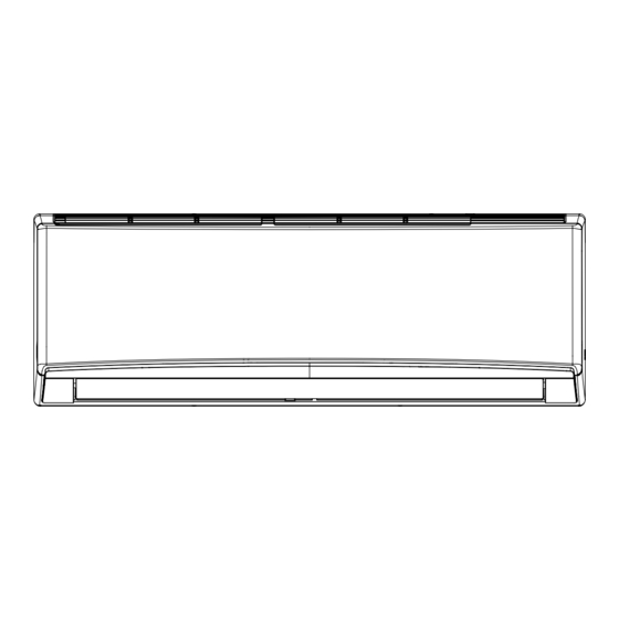
Service Manual 3. Outline Dimension Diagram 3.1 Indoor Unit 168.5 159.5 Φ55 Φ55 Unit:mm Models Technical Information... - Page 12 Service Manual 3.2 Outdoor Unit Unit:mm Unit:mm Technical Information...
-
Page 13: Refrigerant System Diagram
Service Manual 4. Refrigerant System Diagram Cooling and heating model Outdoor unit Indoor unit Gas pipe side Valve 4-Way valve Di s charge Heat Suction Accumlator exchanger Compressor (evaporator) Heat exchanger Liquid pipe (condenser) side Valve Strainer Capillary Strainer COOLING HEATING Technical Information... -
Page 14: Electrical Part
Service Manual 5. Electrical Part 5.1 Wiring Diagram Name Green Yellow Brown COMP Compressor YEGN Violet Orange TUBE ROOM RECEIVER AND TEMP. TEMP. DISPLAY BOARD SENSOR SENSOR DISPLAY T-SENSOR DISP1 DISP2 TERMINAL BLOCK N(1) COM-OUT JUMP PRINTED CIRCUIT BOARD YEGN CONNECTING SWING-UD YEGN... - Page 15 Service Manual 63610000309 Technical Information...
- Page 16 Service Manual 63610000453 Technical Information...
-
Page 17: Pcb Printed Diagram
Service Manual 5.2 PCB Printed Diagram Indoor Unit Top view Name 3 Motor needle stand 9 Interface of display Bottom view Technical Information... - Page 18 Service Manual Outdoor Unit Top view Name Interface of compressor wire Interface of reactor terminal Bottom view Technical Information...
-
Page 19: Function And Control
Service Manual 6. Function and Control 6.1 Remote Controller Introduction Buttons on Remote Controller ON/OFF button T-ON T-OFF MODE button AUTO SWING COOL SLEEP LOCK SPEED HEAT +/- botton MODE ON/OFF FAN button SWING SWING button SLEEP TIMER SLEEP button TIMER button Icon Display on Remote Controller Timer on Timer off... - Page 20 Service Manual When selecting auto mode, air conditioner will operate automatically according to ex-factory setting. Set temperature can't be adjusted and won't be displayed either. Press FAN button to adjust fan speed. (This function is not available in this air conditioner.) When selecting cool mode, air conditioner will operate under cool mode.
- Page 21 Service Manual Replacement of Batteries in Remote Controller battery 1. Press the back side of remote controller on the spot marked with , and then push out the cover of battery box along the arrow direction. 2. Replace two No.7 (AAA 1.5V) dry batteries and make sure the positions of + and -- polar are correct.
-
Page 22: Brief Description Of Modes And Functions
Service Manual 6.2 Brief Description of Modes and Functions 1. Temperature Parameters 2. Basic Functions (1) Cooling Mode Working conditions and process of cooling Cooling conditions and process(09k) Cooling conditions and process(12k) Protection Antifreeze protection state. Total current up and frequency down protection If I total total... - Page 23 Service Manual Working conditions and process of heating Condition and process of defrost (2) -2 (3) -5 (4)-10 Protection Cold air prevention Total current up and frequency down protection total total total total (4) Fan Mode (5) AUTO Mode Working conditions and process of AUTO mode mode.
- Page 24 Service Manual Protection (6) Common Protection Functions and Fault Display under COOL, HEAT, DRY and AUTO Modes Overload protection 1) Cooling overload 2) Heating overload Exhaust temperature protection of compressor Communication fault Module protection Overload protection DC bus voltage protection Faults of temperature sensors Designation of sensors seconds...
-
Page 25: Indoor Units
Service Manual Indoor Units (1) ON/OFF (2) Mode Selection (3) Temperature Setting Option Button Range: 16~30 (4) Time Switch (5) SLEEP State Control C, and it will raise 1 and wind speed. (6) Buzzer Control mode. mode. (7) Auto button (8) Up-and-Down Swinging Control Cooling angle Heating angle... - Page 26 Service Manual from 16 C to 30 (10) Protection function and failure display after defrosted) (11) Drying Function (12) Memory function when interrupting the power supply (13) Sleep function range to operate. operate. Technical Information...
-
Page 27: Part : Installation And Maintenance
Service Manual Part : Installation and Maintenance 7. Notes for Installation and Maintenance Safety Precautions: 10. If the power cord or connection wire is not long enough, please get the specialized power cord or connection wire Important! from the manufacture or distributor. Prohibit prolong the wire by yourself. - Page 28 Service Manual Main Tools for Installation and Maintenance 1. Level meter, measuring tape 2. Screw driver 3. Impact drill, drill head, electric drill 4. Electroprobe 5. Universal meter 6. Torque wrench, open-end wrench, inner hexagon spanner 7. Electronic leakage detector 8.
-
Page 29: Installation
Service Manual 8. Installation 8.1 Installation Dimension Diagram At least 15cm At least 15cm Drainage pipe Installation and Maintenance... -
Page 30: Installation Procedures
Service Manual Installation procedures Start installation Preparation before installation Read the requirements select installation Prepare tools for electric connection location Select indoor unit Select outdoor unit installation location installation location Install the support of outdoor unit Install wall-mounting (select it according to the actual situation) frame, drill wall holes Connect pipes of indoor Fix outdoor unit... -
Page 31: Selection Of Installation Location
Service Manual 8.2 Installation Parts-checking 8.4 Electric Connection Requirement Name Name 1. Safety Precaution Wrapping tape Connection pipe Drainage pipe frame Connecting remote controller conditioner. Wall pipe Note: Air-conditioner 8.3 Selection of Installation Location 1. Basic Requirement: 2. Grounding Requirement: 2. - Page 32 Service Manual 5. Connect the Pipe of Indoor Unit 3. Install Wall-mounting Frame Wall Wall Level meter Mark in the middle of it Space Space to the to the Open-end wall wall wrench above above Union nut 150mm 150mm Pipe Pipe joint Union nut Pipe...
- Page 33 Service Manual 7. Connect Wire of Indoor Unit 8. Bind up Pipe Panel Screw Wiring cover Indoor and outdoor power cord Indoor unit pipe Cable-cross hole Liquid Power connection pipe Band wire Drain hose Drain hose Connection pipe Band Indoor power cord Note: N(1) winding.
-
Page 34: Installation Of Outdoor Unit
Service Manual 8.6 Installation of Outdoor Unit . m) 1. Fix the Support of Outdoor Unit(Select it According to 15~20 the Actual Installation Situation) 30~40 45~55 60~65 expansion screws. 70~75 Note: 5. Connect Outdoor Electric Wire N(1) yellow- green (green) brown(black) blue(white) black brown yellow-... -
Page 35: Check After Installation And Test Operation
Service Manual 8.8 Check after Installation and Test Operation 1. Check after Installation installation. The drain hose can't be fluctuant The water outlet emit noise. can't be placed The drain hose in water can't be fluctuant The water outlet can't be fluctuant water dripping. -
Page 36: Maintenance
Service Manual 9. Maintenance 9.1 Malfunction Analysis Measure insulation resistance The breaker trips at once when it to ground to see if there is any is set to “ON”. leakage. Trip of breaker or blow of fuse The circuit or the part of the air conditioner has malfunction. - Page 37 Service Manual Improper set of temperature Adjust set temperature If cooling (heating) load is Check the forecasted load of cooling (heating) proper Check and fill the leakage, then The refrigerant has leakage or is vacuumize it and supplement the re- insufficient frigerant as required Leakage between the high pres-...
- Page 38 Service Manual Improper set of temperature Adjust set temperature If cooling (heating) load is Check the forecasted load of cooling (heating) proper Check and fill the leakage, then The refrigerant has leakage or is vacuumize it and supplement the re- insufficient frigerant as required Leakage between the high pres-...
- Page 39 Service Manual The torque of the swing motor is not enough First, check whether the connection is Wrong connection The swing fan wrong. If no, replace the parts does not run. The controller is damaged(IC2003 is damaged, the swing relay can not close, etc) C o n t r o l l e r m a l f u n c t i o n ( I C 2 0 0 3 Change controller...
- Page 40 Service Manual 9.2 Flashing LED of Indoor/Outdoor Unit and Primary Judgement Display Method of Outdoor Display Method of Indoor Unit Unit Indicator has 3 kinds of Indicator Display (during display status and during Malfunction blinking, ON 0.5s and OFF Dual-8 A/C status Possible Causes blinking, ON 0.5s and OFF...
- Page 41 Service Manual Display Method of Outdoor Display Method of Indoor Unit Unit Indicator has 3 kinds of Indicator Display (during display status and during Malfunction blinking, ON 0.5s and OFF Dual-8 A/C status Possible Causes blinking, ON 0.5s and OFF Name 0.5s) Code...
- Page 42 Service Manual Display Method of Outdoor Display Method of Indoor Unit Unit Indicator has 3 kinds of Indicator Display (during display status and during Malfunction blinking, ON 0.5s and OFF Dual-8 A/C status Possible Causes blinking, ON 0.5s and OFF Name 0.5s) Code...
- Page 43 Service Manual Display Method of Outdoor Display Method of Indoor Unit Unit Indicator has 3 kinds of Indicator Display (during display status and during Malfunction blinking, ON 0.5s and OFF Dual-8 A/C status Possible Causes blinking, ON 0.5s and OFF Name 0.5s) Code...
- Page 44 Service Manual Display Method of Outdoor Display Method of Indoor Unit Unit Indicator has 3 kinds of Indicator Display (during display status and during Malfunction blinking, ON 0.5s and OFF Dual-8 A/C status Possible Causes blinking, ON 0.5s and OFF Name 0.5s) Code...
- Page 45 Service Manual Display Method of Outdoor Display Method of Indoor Unit Unit Indicator has 3 kinds of Indicator Display (during display status and during Malfunction blinking, ON 0.5s and OFF Dual-8 A/C status Possible Causes blinking, ON 0.5s and OFF Name 0.5s) Code...
- Page 46 Service Manual Display Method of Indoor Unit Display Method of Outdoor Unit Indicator Display (during Indicator has 3 kinds of display blinking, ON 0.5s and OFF status and during blinking, ON Dual-8 Malfunction A/C status Possible Causes 0.5s) 0.5s and OFF 0.5s Code Name Operation...
- Page 47 Service Manual Installation and Maintenance...
- Page 48 Service Manual Analysis or processing of some of the malfunction display: 1. Compressor discharge protection 2. Low voltage overcurrent protection 3. Communication malfunction 4. Sensor open or short circuit 5. Compressor over load protection 6. System malfunction 7. IPM module protection Installation and Maintenance...
-
Page 49: How To Check Simply The Main Part
Service Manual 9.3 How to Check Simply the Main Part Indoor Unit (1) Malfunction of Temperature Sensor F1, F2 Main detection points: Troubleshooting for F1,F2 malfunction the wiring terminal between the temperature sensor and the controller loosened or poorly contacted? Insert the temperature sensor tightly Is malfunction... - Page 50 Service Manual (2) Malfunction of Blocked Protection of IDU Fan Motor H6 Main detection points: Start While power is off stir the blade with a tool to see whether the blade rotates smoothly Tighten the screw; reassemble the blade, motor and shaft bearing rubber base sub-assy to make sure there is no foreign object between them Is malfunction...
- Page 51 Service Manual (3) Malfunction of Protection of Jumper Cap C5 Main detection points: Troubleshooting for C5 malfunction Appearance of Is there jumper cap on the the jumper cap mainboard ? Assemble the jumper cap with the same model Is malfunction eliminated the jumper cap inserted correctly and...
- Page 52 Service Manual (4) Malfunction of Zero-crossing Inspection Circuit Malfunction of the IDU Fan Motor U8 Main detection points: Instant energization afte de-energization while the capacitordischarges slowly? Malfunction diagnosis process: Troubleshooting for U8 malfunction Turn power off for 1minute,the turn back on The unit returns to normal.
-
Page 53: Outdoor Unit
Service Manual Outdoor Unit (1) Capacitor charge fault (Fault with outdoor unit) (AP1 below refers to the outdoor control panel) Troubleshooting for F1,F2 malfunction the wiring terminal between the temperature sensor and the controller loosened or poorly contacted? Insert the temperature sensor tightly Is malfunction eliminated... - Page 54 Service Manual (2) IPM Protection, Out-of-step Fault, Compressor Phase Overcurrent (AP1 below refers to the outdoor control panel) Energize and switch on Use AC voltmeter If the voltage Check the supply to measure the IPM protection between terminal L voltage and voltage between occurs after the and N on wiring...
- Page 55 Service Manual (3)High temperature and overload protection diagnosis (AP1 hereinafter refers to the control board of the outdoor unit) Mainly detect: Overheat and high temperature protection Normal protection, please operate it after the outdoor ambient temp- Is outdoor ambient temperature higher than 53? erature is normalized.
- Page 56 Service Manual (4) Start-up failure (following AP1 for outdoor unit control board) Mainly detect: Power on the unit Restart it up after Is stop time of the compressor 3 minutes longer than 3 minutes? Does startup fail? Connect the wires as Are the wires for the compressor connected per the connection correctly? Is connection sequence right?
- Page 57 Service Manual (5) Out of step diagnosis for the compressor (AP1 hereinafter refers to the control board of the outdoor unit) Mainly detect: Out of step occurs in Out of step occurs once the operation unit is powered on. Check if the fan terminal Is stop time of the Replace the fan Is the outdoor fan working...
- Page 58 Service Manual (6) Overload and air exhaust malfunction diagnosis (following AP1 for outdoor unit control board) Mainly detect: 20 minutes after the complete unit is powered off Is the terminal FA for the Connect the electronic expansion valve wires correctly connected correctly? Resistances between the first four pins close to the terminal hole and the fifth...
- Page 59 Service Manual (7) Power factor correct or (PFC) fault (a fault of outdoor unit) (AP1 hereinafter refers to the control board of the outdoor unit) Mainly detect: Start Check wiring of the reactor (L) of the outdoor unit and the PFC capacitor Replace it as per the Whether there is any...
- Page 60 Service Manual (8) Communication malfunction: (following AP1 for outdoor unit control board) Mainly detect: Start Did the equipment operate normally before the failure occurs? Check the wiring of the indoor and outdoor units with reference to the wiring diagram Check wiring inside of the indoor and outdoor Is the connection right? units...
- Page 61 Service Manual (9) Malfunction of Overcurrent Protection E5 Main detection points: Start Is the supply voltage unstable Normal fluctuation should be within 10 % of the Malfunction is with big fluctuation? rated voltage on the nameplate eliminated Is the supply voltage too low Malfunction is Malfunction is Adjust the supply voltage to maintain it within...
-
Page 62: Exploded View And Parts List
Service Manual 10. Exploded View and Parts List 10.1 Indoor Unit T-ON T-OFF AUTO SWING COOL SLEEP LOCK SPEED HEAT ON/OFF MODE SWING SLEEP TIMER Installation and Maintenance... - Page 63 Service Manual Part Code Description CB427N04800 CB427N04700 2002269601S 2002269601S 11122219 11122219 Display Board 30565265 30565265 2002273001 2002273001 1051276301 1051276301 26112508 26112508 10512037 10512037 Rear Case assy 20162010 20162010 Drainage Hose 0523001408 0523001408 Ring of Bearing 26152022 26152022 7651205102 7651205102 24212180 24212180 Cold Plasma Generator 1114001602...
- Page 64 Service Manual Part Code Description CB434N04500 CB438N03000 20000300026T 20000300073T 11122219 11122219 Display Board 30565260 30565260 00000200040 00000200040 1051276301 1051276301 26112508 26112508 10512037 10512037 Rear Case assy 20162010 20162010 Drainage Hose 0523001408 0523001408 Ring of Bearing 26152022 26152022 7651205102 7651205102 24212180 24212180 Cold Plasma Generator 1114001602...
- Page 65 Service Manual Part Code Description CB438N03001 CB427N04801 20000300073T 20000300073T 11122219 11122219 Display Board 30565260 30565260 00000200040 00000200040 1051276301 1051276301 26112508 26112508 10512037 10512037 Rear Case assy 20162010 20162010 Drainage Hose 0523001408 0523001408 Ring of Bearing 26152022 26152022 7651205102 7651205102 24212180 24212180 Cold Plasma Generator 1114001602...
- Page 66 Service Manual Part Code Description CB419N08700 CB432N05200 20022479S 20000300019S 11122219 11122219 Display Board 30565263 30565260 00000200128 00000200040 10512722 1051276301 26112508 26112508 10512037 10512037 Rear Case assy 20162010 20162010 Drainage Hose 0523001408 0523001408 Ring of Bearing 26152022 26152022 7651205102 7651205102 24212180 24212180 Cold Plasma Generator 1114001602...
- Page 67 Service Manual Part Code Description CB419N08800 CB434N04400 20022479S 20000300026T 11122219 11122219 Display Board 30565263 30565260 00000200128 00000200040 10512722 1051276301 26112508 26112508 10512037 10512037 Rear Case assy 20162010 20162010 Drainage Hose 0523001408 0523001408 Ring of Bearing 26152022 26152022 7651205102 7651205102 24212180 24212180 Cold Plasma Generator 1114001602...
- Page 68 Service Manual Part Code Description CB438N03200 CB438N03201 20000300073T 20000300073T 11122219 11122219 Display Board 30565260 30565260 00000200040 00000200040 1051276301 1051276301 26112508 26112508 10512037 10512037 Rear Case assy 20162010 20162010 Drainage Hose 0523001408 0523001408 Ring of Bearing 26152022 26152022 7651205102 7651205102 24212180 24212180 Cold Plasma Generator 1114001602...
- Page 69 Service Manual Part Code Description CB427N04701 2002269601S 11122219 Display Board 30565265 2002273001 1051276301 26112508 10512037 Rear Case assy 20162010 Drainage Hose 0523001408 Ring of Bearing 26152022 7651205102 24212180 Cold Plasma Generator 0100200004407 01252043 10352059 150120874 Connecting pipe clamp 2611216401 76712012 Stepping Motor 1521212901 73012005...
- Page 70 Service Manual 10.2 Outdoor Unit 21 22 25 26 Installation and Maintenance...
- Page 71 Service Manual Part Code Description CB427W04800 Small Handle 26233100 01207200061P 01703246 Condenser Assy 01100200412 1501308506 Coping 01253305 Rear Grill 01473079 0123338502 0010389603 76710302 03073151 Big Handle 2623343106 03005700067 07133474 26113017 22413049 0220010000111 10333004 01700000217P Electric Box Assy 10000100576 Electric Box 20113032 Main Board 30138000849...
- Page 72 Service Manual 25 26 Installation and Maintenance...
- Page 73 Service Manual Part Code Description CB427W04700 Handle 26233014 01207200062P 0170324701 Condenser Assy 01100200658 15013085 Coping 01253106P Rear Grill 01473080 0123316001 00103364 030152000016 Big Handle 2623343106 03005700067 07133474 26113017 01473080 01433075P 10333011 01700000214P Electric Box Assy 10000100825 Electric Box 20113032 Main Board 30138001122 Reactor 43130184...
-
Page 74: Removal Procedure
Service Manual 11. Removal Procedure Caution: discharge the refrigerant 11.1 Removal Procedure of Indoor Unit completely before removal. Step Procedure 1. Remove filter assembly Front panel Open the front panel. Push the left filter and right filter until they are separate from the groove on the front panel. - Page 75 Service Manual Step Procedure 4. Remove electric box cover 2 Screw Electric box cover 2 Remove the screws on the electric box cover 2 to remove the electric box cover 2. 5. Remove front case sub-assy Screws Remove the screws fixing front case. Note: 1.Open the screw caps before removing the screws around the air outlet.
- Page 76 Service Manual Step Procedure 7. Remove electric box assy Screw Loosen the connection clasps between shield cover of electric box sub-assy and Clasps electric box, and then remove the shield cover of electric box sub-assy. Remove the screw fixing electric box assy . Electric box Shield cover of electric box sub-assy...
- Page 77 Service Manual Step Procedure Instruction: Some wiring terminal of this product is with lock catch and other devices. circlip The pulling method is as below: holder 1.Remove the soft sheath for some terminals at first, hold the circlip and then pull out the terminals.
- Page 78 Service Manual Step Procedure 9. Remove motor and cross flow blade Remove the screws fixing motor clamp Screws and then remove the motor clamp. Motor clamp Cross flow Remove the screws at the connection Screw Motor place of cross flow blade and motor; lift Holder the motor and cross flow blade upwards sub-assy...
-
Page 79: Removal Procedure Of Outdoor Unit
Service Manual 11.2 Removal Procedure of Outdoor Unit Warning: Be sure to wait for a minimum of 20 minutes after turning off all power supplies and discharge the refrigerant completely before removal. Steps Procedure 1.Remove handle Before disassamble. Remove 1 connection screw fixing handleand then removethe handle. - Page 80 Service Manual Steps Procedure 3.Remove grille and front panel Remove connection screws between the front grille and the front panel. Then remove the front grille. Remove connection screws connecting the front panel with the chassis and the motor support, and then remove the front panel.
- Page 81 Service Manual Steps Procedure 6.Remove electric box assy Electric box assy Remove the 2 screws fixing the cover of elec- tric box. Lift to remove the cover. Loosen the wire and disconnect the terminal. Lift to re- move the electric box assy. 7.Remove 4-way valve assy Unscrew the fastening nut of the 4-way Valve 4-way Valve Assy...
- Page 82 Service Manual Steps Procedure 9.Remove motor and motor support Motor support Remove the 4 tapping screws fixing the motor. Pull out the lead-out wire and remove the Motor motor. Remove the 2 tapping screws fixing the motor support. Lift motor support to re- move it.
- Page 83 Service Manual Steps Procedure 11.Remove Compressor Remove the 2 screws fixing the gas valve. Unsolder the welding spot connecting gas valve and air return pipe and remove the gas valve. (Note: it is necessary to warp the gas valve when unsoldering the welding spot.) Remove the 2 Liquid valve screws fixing liquid valve.
- Page 84 Service Manual Steps Procedure 1. Before disassembly 2. Remove big handle 3. Remove top cover panel. Installation and Maintenance...
- Page 85 Service Manual Steps Procedure 4. Remove grille grille 5. Remove front panel panel. front panel 6. Remove right side plate and support plate Installation and Maintenance...
- Page 86 Service Manual Steps Procedure 8. Remove motor and motor support motor motor. 9. Remove Electric Box Assy Electric Box Assy 10. Remove isolation sheet 11. Remove compressor Installation and Maintenance...
- Page 87 Service Manual Steps Procedure compressor. compressor Installation and Maintenance...
-
Page 88: Appendix
Service Manual Appendix: Appendix 1: Reference Sheet of Celsius and Fahrenheit Conversion formula for Fahrenheit degree and Celsius degree: Tf=Tcx1.8+32 Set temperature display display display 60.8 69.8 78.8 62.6 71.6 80.6 64.4 73.4 82.4 66.2 75.2 84.2 Ambient temperature display display display 55.4... - Page 89 Service Manual Appendix 3: Pipe Expanding Method Pipe Note: Pipe cutter Improper pipe expanding is the main cause of refrigerant leakage.Please expand the pipe according to the following steps: Leaning Uneven Burr Pipe Shaper Downwards Union pipe Pipe Hard mold Note: Expander A(mm)
- Page 90 Service Manual Appendix 4: List of Resistance for Temperature Sensor Resistance Table of Ambient Temperature Sensor for Indoor and Outdoor Units (15K) Temp( Temp( Temp( Temp( 138.1 18.75 3.848 1.071 128.6 17.93 3.711 1.039 121.6 17.14 3.579 1.009 16.39 3.454 0.98 108.7 15.68...
- Page 91 Service Manual Resistance Table of Tube Temperature Sensors for Outdoor and Indoor (20K) Temp( Temp( Temp( Temp( 181.4 25.01 5.13 1.427 171.4 23.9 4.948 1.386 162.1 22.85 4.773 1.346 153.3 21.85 4.605 1.307 20.9 4.443 1.269 137.2 4.289 1.233 129.9 19.14 4.14 1.198...
- Page 92 Service Manual Resistance Table of Discharge Temperature Sensor for Outdoor (50K) Temp( Temp( Temp( Temp( 853.5 18.34 4.75 799.8 93.42 17.65 4.61 89.07 16.99 4.47 703.8 84.95 16.36 4.33 660.8 81.05 15.75 4.20 620.8 77.35 15.17 4.08 580.6 73.83 14.62 3.96 548.9 70.5...
- Page 93 GREE ELECTRIC APPLIANCES,INC.OF ZHUHAI Add: West Jinji Rd, Qianshan, Zhuhai, Guangdong, China 519070 Tel: (+86-756) 8522218 Fax: (+86-756) 8669426 Email: gree@gree.com.cn Http://www.gree.com HONG KONG GREE ELECTRIC APPLIANCES SALES LIMITED Add: Unit 2612,26/F.,Miramar Tower 132 Nathan Road,TST,Kowloon,HK Tel: (852) 31658898 Fax: (852) 31651029...