Table of Contents
Advertisement
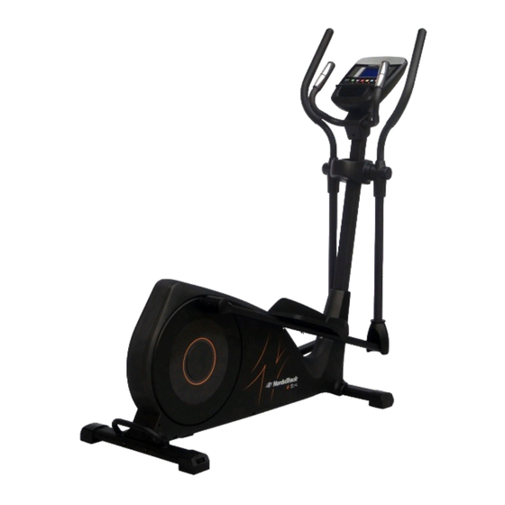
Model No. : NTIVEL77014.0
Serial No. : ___________
Serial number decal
Write the serial number in the
space above for reference.
STEP 10
QUESTIONS ?
If you have questions, or if there are
missing parts, please contact us:
UK
Call: 0330 1231045
From Ireland: 053 92 36102
Website: www.iconsupport.eu
E-mail: csuk@iconeurope.com
Write:
ICON Health & Fitness, Ltd.
Unit 1D Fryers Way, Ossett,
WF5 9TJ
UK
CAUTION
Read all precautions and instruc-
tions in this manual before using
this equipment. Keep this manual
for future reference.
USERʼS MANUAL
Visit our website
www.iconsupport.eu
Advertisement
Table of Contents

Related Manuals for NordicTrack E 5.4


Summary of Contents for NordicTrack E 5.4
- Page 1 USERʼS MANUAL Model No. : NTIVEL77014.0 Serial No. : ___________ Serial number decal Write the serial number in the space above for reference. STEP 10 QUESTIONS ? If you have questions, or if there are missing parts, please contact us: Call: 0330 1231045 From Ireland: 053 92 36102 Website: www.iconsupport.eu...
-
Page 2: Table Of Contents
TABLE OF CONTENTS MAINTENANCE AND TROUBLESHOOTING............. . 2 IMPORTANT PRECAUTIONS . -
Page 3: Important Precautions
IMPORTANT PRECAUTIONS WARNING : To reduce the risk of serious injury, read all important precautions and instructions in this manual and all warnings on your elliptical before using your elliptical. ICON assumes no responsibility for personal injury or property damage sustained by or through the use of this product. -
Page 4: Before You Begin
The model number is NTIVEL77014.0 and the loca- Track® E 5.4. The elliptical provides an array of features designed to make your workouts at home tion of the serial number decal are shown on the more effective and enjoyable. -
Page 5: Assembly
ASSEMBLY Assembly requires two persons. Place all parts of the elliptical exerciser in a cleared area and re- move the packing materials. Do not dispose of the packing materials until assembly is completed. In addition to the included tool(s), assembly requires a Phillips screwdriver an adjustable wrench. - Page 6 STEP 1 Fasten front stabilizer (37) with 2 Allen bolts (83) from the underside of stabilizer. Fasten Rear stabilizer (82) with 2 Allen bolts (83). STEP 2 I. Carefully lift the Handlebar Post (18) until it is vertical. Put the front plastic cover (90) into the Handlebar post (18).
- Page 7 STEP 4 Slide the upper swing bar Left and Right (8) onto the Center Shaft and secure using curved washers (19) 2 coated Allen Bolts (23), 2 wave washers (21), 2 spring pad (22). Fit the lower swing bar Left and Right (15) by slotting them into the upper swing bar Left and Right (8) and loosely fit 4 Allen bolts (14) and 4 nut (16).
- Page 8 STEP 5 Fasten right footplate (25R) with Allen bolts (39),spring pad (22),washer (40) from the right footplate support bar and secure it tightly. Do the same for the left pedal. STEP 6 Fasten Handle Bar (10) to Handlebar Post and secure it with Allen Bolt (34), Curved washer (13) and spring pad(22).
- Page 9 STEP 8 Connect the Upper Computer Cable and two hand pulse cable (6) with the cable on back of computer (1).Sit the computer (1) onto its bracket and secure in place using the 4 screws. STEP 9 Secure plastic cover (12) onto the handlebar post with a screw(11) Note: Before using the machine, make sure all the...
-
Page 10: How To Operate The Elliptical
CONSOLE DIAGRAM MAKE YOUR FITNESS GOALS A REALITY WITH Upload your workout results to the iFit cloud IFIT.COM and track your accomplishments. With your new iFit-compatible fitness equipment, you can use an array of features on iFit.com to make your Set calorie, time, or distance goals for your fitness goals a reality: workouts. -
Page 11: Features Of The Console
FEATURES OF THE CONSOLE Note: After you press a button, it will take a moment The advanced console offers an array of features for the pedals to reach the selected resistance level. designed to make your workouts more effective and 4. - Page 12 As you exercise, the workout intensity level bar Note: If the pedals do not move for about thirty sec- will indicate the approximate intensity level of your onds, the fan will turn off automatically. exercise. 7. When you are finished exercising, the console will turn off automatically.
- Page 13 Each workout is divided into one-minute seg- 7. When you are finished exercising, the console will turn off automatically. ments. One resistance level and one target speed is programmed for each segment. Note: The same resistance level and/or target speed may be pro- See step 7 on page 19.
- Page 14 See step 6 on page 19. For more information about the iFit workouts, please see www.iFit.com. 7. When you are finished exercising, the console will turn off automatically. When you select an iFit workout, the display will show the duration of the workout and the approximate See step 7 on page 19.
- Page 15 HOW TO CHANGE CONSOLE SETTINGS Press the Enter button. After a few seconds, the sta- tus of the iFit module will appear in the display. To exit 1. Select the settings mode. this display, press the Settings button. Send/Receive—The words SEND/RECEIVE DATA To select the settings mode, press the Settings button.
-
Page 16: How To Use The Elliptical
MAINTENANCE AND TROUBLESHOOTING Important: To avoid damaging the console, keep Inspect and tighten all parts of the elliptical regularly. liquids away from the console and keep the console Replace any worn parts immediately. out of direct sunlight. To clean the elliptical, use a damp cloth and a small amount of mild detergent. -
Page 17: Exercise Guidelines
EXERCISE GUIDELINES Burning Fat—To burn fat effectively, you must exercise WARNING: at a low intensity level for a sustained period of time. Before beginning this During the first few minutes of exercise, your body uses or any exercise program, consult your physi- carbohydrate calories for energy. -
Page 18: Exploded Drawings
EXPLODED DRAWING—Model No. NTIVEL77014.0... -
Page 19: Part List
PART LIST—Model No. NTIVEL77014.0 Item Qty. Description Item Qty. Description Computer Drill Screw M5*15 Screw Sensor with Cable 800mm End Cap Φ32 C-Sharp Clip Φ8 Hand pulse pads Φ32 Curved Washer Φ10*Φ15*0.5T screw M2.5*33 Washer Φ10*Φ15*1.0T Hand pulse cable 550mm Oppress Pole Center Shaft Plastic Cover L Axis Φ10*42... -
Page 20: Ordering Replacement Parts
ORDERING REPLACEMENT PARTS To order replacement parts, please see the front cover of this manual. To help us assist you, be prepared to provide the following information when contacting us: • the model number and serial number of the product (see the front cover of this manual) •...