Table of Contents
Advertisement
Quick Links
48/50HC 04---28
Single Package Rooftop Units
with ComfortLink Controls Version 1.X
and PURONr (R---410A) Refrigerant
IMPORTANT: This literature covers 48/50HC 04- -28 models with
ComfortLink Software version 1.X.
TABLE OF CONTENTS
. . . . . . . . . . . . . . . . . . . . . . . . . . . . . . . . . . . . . . . . .
. . . . . . . . . . . . . . . . . . . . . . . . . . . . . . . .
. . . . . . . . . . . . . . . . . . . . . . . . . . . . . . . . . .
. . . . . . . . . . . . . . . . . . . . . . . . . . . . . . . . . . . . . . . . .
. . . . . . . . . . . . . . . . . . . . . . . . . . . . .
. . . . . . . . . . . . . . . . . . . . . . . . . . . . . . . . . . . . . . . . .
. . . . . . . . . . . . . . . . . . . . . . . . . . . . . . . . . . . .
. . . . . . . . . . . . . . . . . . . . . . . . . . . . . . .
. . . . . . . . . . . . . . . . . . . . . . . . . . . . .
. . . . . . . . . . . . . . . . . . . . . . . . . . . . . . . . .
. . . . . . . . . . . . . . . . . . . . . . . . . . . . . . . .
. . . . . . . . . . . . . . . . . . . . . . . . . . . . . . . . . . . . .
. . . . . . . . . . . . . . . . . . . . . . . . . . . . . . . . . . . . .
. . . . . . . . . . . . . . . . . . . . . . . . . . . . . . . . . . . .
. . . . . . . . . . . . . . . . . . . . . . . . . . . . . . . . . .
. . . . . . . . . . . . . . . . . . . . . . . . . . . .
. . . . . . . . . . . . . . . . . . . . . . . . . . . . . . .
. . . . . . . . . . . . . . . . . . . . . . . . . . . . . .
. . . . . . . . . . . . . . . . . . . . . . . . . . . . . . . . . . .
. . . . . . . . . . . . . . . . . . . . . . . . . . . . . . . . . . . . . . . . .
. . . . . . . . . . . . . . . . . . . . . . . . . . . . . . . . .
. . . . . . . . . . . . . . . . . . . . . . . . . . . . .
. . . . . . . . . . . . . . . . . . . . . . . . . . . . . . .
. . . . . . . . . . . . . . . . . . . . . . . . . . . . . . . .
Controls, Start---Up, Operation
and Troubleshooting
. . . . . . . . . . . . . . . . . . . . . . . . .
. . . . . . . . . . . . . . . . . . . . . . . . . . .
. . . . . . . . . . . . . . . . . . . . . . . . . .
. . . . . . . . . . . . . . . . .
. . . . . . . . . . . . . . . . . . . . . .
. . . . . . . . . . . . . . . . . . . . . . . . . . .
. . . . . . . . . . . . . . . . . . . . . . . . .
. . . . . . . . . . . . . . . . .
. . . . . . . . . . . . . . . . . . . .
. . . . . . . . . . . . .
Page
. . . . . . . . . . . . . . . . . . . . . . . . . . . . . . . . . . . . . . .
2
3
. . . . . . . . . . . . . . . . . . . . . . . . . . . . . . . . . . . .
3
3
. . . . . . . . . . . . . . . . . . . . . . . . . . . . . . . . . . . . . . . . .
3
. . . . . . . . . . . . . . . . . . . . . . . . . . . . . . . . . . . . .
4
4
. . . . . . . . . . . . . . . . . . . . . . . . . . . . . . . . . . . . . .
4
4
6
6
6
. . . . . . . . . . . . . . . . . . . . . . . . . . . . . . . . . . . .
6
. . . . . . . . . . . . . . . . . . . . . . . . . . . . . . . . . . . . .
6
6
6
6
6
. . . . . . . . . . . . . . . . . . . . . . . . . . . . . . . . . . . . . . . . . .
6
7
7
7
7
7
. . . . . . . . . . . . . . . . . . . . . . . . . . . . . . . . . . . . . .
8
8
9
. . . . . . . . . . . . . . . . . . . . . . . . . . . . . . . . . . . . . . . .
9
9
. . . . . . . . . . . . . . . . . . . . . . . . . . . . . . . . . . . .
9
. . . . . . . . . . . . . . . . . . . . . . . . . . . . . . . . . . . . . . . . .
9
9
9
9
. . . . . . . . . . . . . . . . . . . . . . . . . . . .
. . . . . . . . . . . . . . . . . . . . . .
. . . . . . . . . . . . . . . . . . . . . . . . . . . . . . .
. . . . . . . . . . . . . . . . . . . .
. . . . . . . . . . . . . . . . . . . . . . . . . . . . . . .
. . . . . . . . . . . . . . . . . . . . . . . . . . . . . .
. . . . . . . . . . . . . . . . . . . . . . . . . .
. . . . . . . . . . . . . . . . . . . . . . . . . . . .
. . . . . . . . . . . . . . . . . . . . . . . . . . .
. . . . . . . . . . . . . . . . . . . . . . . . . . . . . . . .
. . . . . . . . . . . . . . . . . . . . . . . . .
. . . . . . . . . . . . . . . . . . . . . . . . . . .
. . . . . . . . . . . . . . . . . . . . . . . . . . . . . .
. . . . . . . . . . . . . . . . . . . . . . . . . . . . . . . . .
. . . . . . . . . . . . . . . . . . . . . . . . . . . . . . . . .
. . . . . . . . . . . . . . . . . . .
. . . . . . . . . . . . . . . . . . . . . . . . . . .
. . . . . . . . . . . . . . . . . . . . . . . . . . . . . . . . .
. . . . . . . . . . . . . . . . . . . . . . . . . . . . . . . . .
. . . . . . . . . . . . . . . . . . . . . . . . . . . .
. . . . . . . . . . . . . . . . . . . . . . .
. . . . . . . . . . . . . . . . . . . . . . . . . . . . . . . . . . .
. . . . . . . . . . . . . . . . . . . . . . . . . . . . . .
. . . . . . . . . . . . . . . . . . . . . . . . . . . .
. . . . . . . . . . . . . . . . . . . . . . . . . . . . . . . . . .
9
9
9
9
10
12
12
12
12
12
13
13
13
13
13
13
13
13
14
14
14
14
15
15
16
18
19
21
23
. . . . . .
24
29
29
. . . . . . . . .
30
30
31
31
31
32
32
Advertisement
Table of Contents
Troubleshooting

Related Manuals for Carrier 48HC 04-28


Summary of Contents for Carrier 48HC 04-28
-
Page 1: Table Of Contents
....... . . Carrier Comfort Network (CCN)R Configuration .. -
Page 2: Safety Considerations
..... . . suggestions which will result in enhanced installation, reliability, or operation. Carrier Comfort Network (CCN) Interface ... . . -
Page 3: General
Marquee, the user can access a built-in test routine that can be used and troubleshoot. at start-up commissioning and to diagnose operational problems The ComfortLink control is fully communicating and cable-ready with the unit. (See Table 2.) for connection to the Carrier Comfort Network® (CCN) building management system. control provides high-speed communications for remote monitoring via the Internet. -
Page 4: Accessory Navigator Display
3V zoning system, linkage compatible air source, lines of display and the Scrolling Marquee has a single line. All universal controller, and all other devices operating on the Carrier further discussions and examples in this document will be based on communicating network. - Page 5 Table 2 – Scrolling Marquee Mode and Menu Display Structure SERVICE TIME OPERATING TEMPERATURES PRESSURES SETPOINTS INPUTS OUTPUTS CONFIGURATION ALARMS STATUS TEST CLOCK MODES Time of Auto View Service Test Thermostat Display Control Reset All Configuration Mode Temperatures Inputs Outputs Modes Current (DISP)
-
Page 6: Conventions Used In This Manual
Conventions Used in This Manual phase-rotation meter on the unit input power to check for L1-L2-L3 or clockwise rotation or use the Service Test mode to The following conventions for discussing configuration points for energize a compressor. If the compressor is rotating in the wrong the local display (Scrolling Marquee or Navigator™... -
Page 7: Condenser Fans And Motors
High Altitude section to identify the correct orifice size for the (IDF.C) Economizer Position Test (Service elevation. Purchase these orifices from your local Carrier dealer. Test INDP ECON) to 0 (Economizer Damper Closed) and → → Follow instructions in accessory Installation Instructions to install... -
Page 8: Gas Heat (48Hc)
INDOOR BLOWER ACCESS PANEL OUTDOOR AIR SCREEN (HIDDEN) GAS SECTION ACCESS PANEL FILTER AND CONTROL BOX INDOOR COIL ACCESS PANEL ACCESS PANEL C11475 Fig. 5 - - 48/50HC MRT Units, Panel and Filter Locations (48HC*17 Unit Shown) Gas Heat (48HC) 3. -
Page 9: Controls Quick Set- -Up
CONTROLS QUICK SET- -UP supply duct SAT, the heating mode display is enabled by setting Configuration→HEAT→SAT.H to ENBL. The following information will provide a quick guide to setting up Installation of an accessory return air temperature (RAT) sensor in and configuring the 48/50HC series units with ComfortLink the return duct and wired to the space sensor input is recommended controls. -
Page 10: Programming Operating Schedules
Power Exhaust Programming Operating Schedules If a Power Exhaust accessory was field installed, the unit must be The ComfortLink controls will accommodate up to eight different configured for it by setting Configuration→ECON→PE.EN to schedules (Periods 1 through 8), and each schedule is assigned to ENBL. - Page 11 Table 3 – Setting an Occupied Time Schedule — Weekdays Only for 7:30 to 22:30 DISPLAY SUB-SUB KEYPAD ITEM DISPLAY ITEM EXPANSION COMMENT MENU MODE ENTRY TIMECLOCK ENTER Local Occupancy Schedule SCH.L PER.1 ENTER OCC.1 Period Occupied Time ENTER 00.00 Scrolling stops ENTER 00.00...
-
Page 12: Service Test
SERVICE TEST Humidi- -MiZert Test For units with the factory Humidi-MiZer™ option, the Humidi-MiZer The Service Test function can be used to verify proper operation of (HZMR) submenu is used to change the output status to operate the compressors, heating stages, Humidi- -MiZert System, indoor fan, circuits in different Humidi- -MiZer modes or to separately test the power exhaust fans, economizer, and the alarm relay. -
Page 13: Heating Test
Heating Test Remote Occupancy The heating (HEAT) submenu is used to change output status for The remote occupancy input is provided on the field connection the individual heat stages, gas or electric. The fans (FANS) and terminal board (TB). Remote Occupancy Switch cooling (COOL) service test outputs are reset to OFF for the... -
Page 14: Controls Operation
CONTROLS OPERATION Remote Occupancy Switch (RM.SW) This configuration identifies if a remote occupancy switch is Display Configuration installed, and what status (normally open, normally closed) the The Configuration→DISP submenu is used to configure the local input is when UNOCCUPIED. display settings. SAT Settling Time (SAT.T) Metric Display (METR) This configuration sets the settling time of the supply air... -
Page 15: General Operation
System Mode (SYS) Timed Override in Effect (T.OVR) In Run Status and Operating Modes, the current system mode is Displays if the state of occupancy is currently occupied due to an displayed with expandable text. This is an overall state of the unit. override. -
Page 16: Occupancy Determination
Level 3 Priority When the space sensor has a setpoint slider adjustment, the cool and heat setpoints (occupied) can be offset by sliding the bar from The following occupancy options are determined by the state of one side to the other. The SPT Offset Range (+/- -) (Setpoints Occupancy Schedule Number (Configuration→CCN→SCH.O →STO.R) sets the total positive or negative degrees that can be →SCH.N) and the Global Schedule Broadcast (Configuration... - Page 17 Staged Air Volume (SAV) Units (FTYP = LEN VFD) Fan Speed - Free Cool Lo (FS.E1) This configuration defines the initial fan speed used when in Free The SAV Option is a new method of controlling the supply fan in a Cooling.
-
Page 18: Cooling Operation
Constant Volume (CV) Units (FTYP = 1- - Speed) Staging Control Single speed fan units are controlled by the Indoor Fan Relay 1 Once the unit is in a cooling mode, it must decide what the demand (Outputs →FANS →IDF.1) on the main base board (MBB), is and how to satisfy it. -
Page 19: Heating Operation
(Operating Modes →COOL →HMZR→REQ.R) and run the indoor expire before another stage can be added or a stage can be fan at Fan Speed - Reheat2 (Configuration →I.FAN →FS.RH). subtracted. If at any time the Supply- -Air Temperature (SAT) falls During this condition the Dehumidification Active? (Operating below the Minimum Supply Air Temperature Upper Level Modes →COOL →ACT.D) status point will be yes. - Page 20 Heat Relay Control There are two supply air temperature limits that affect heating operation, the Maximum SAT Lower Level (Configuration The heat relay control is responsible for energizing or →HEAT→SAT→SAM.L) the Maximum SAT Upper Level de- -energizing the MBB’s heat stage relays and works hand in hand (Configuration→HEAT→SAT→SAM.U).
-
Page 21: Economizer
Economizer or commanded position when E.CTL =2. Because the wiring has a built- -in 500- -ohm resistor, the 4 to 20mA signal is converted to a 2 If an economizer is installed, then Economizer Installed to 10VDC signal at the actuator. (Configuration→ECON→EC.EN) should be set to YES. - Page 22 The shape of the Economizer Minimum Position vs. Fan Speed compressor is ON, the economizer will be at the economizer curve is determined by the configuration parameters: Econ Min at maximum cooling position (Configuration→ECON→EC.MX). 25% Fan speed (Configuration→ECON→MP.25), Econ Min at If the control senses low suction pressure for any active refrigerant 50% Fan speed (Configuration→ECON→MP.50), Econ Min at circuit when the economizer is also providing cooling, the...
-
Page 23: Indoor Air Quality (Iaq)
Power Exhaust (SAVt units) The ComfortLink control will begin to open the damper from the Econo Min IAQ Position (AQ.MN) position when the IAQ level To enable power exhaust, set Power Exhaust Installed begins to exceed the Outdoor Air Quality (OAQ) level by a (Configuration→ECON→PE.EN) to YES. -
Page 24: Optional Humidi- -Mizert Dehumidification System
Fan Enable (Analog IAQ Sensor) IA.CF = 3 (Control Minimum Position) When IA.CF = 3, an external 4 to 20 mA source is used to set the The DCV algorithm will operate whenever the building is minimum position. The 4mA signal corresponds to 0% and the 20 occupied and the indoor fan is operating or whenever the IAQ mA signal corresponds to 100%. - Page 25 Sensor Value at 4ma (Configuration→AIR.Q→H.4M) sets the % NOTE: Compressor staging control for Humidi- -MiZer units display for a 4mA input from the relative humidity sensor. RH requires that circuit A always operates when circuit B is on. This Sensor Value at 20ma (Configuration→AIR.Q→H.20M) sets the applies to normal operation, service test, and for control alarm % display for a 20mA input from the relative humidity sensor.
- Page 26 RDV.x RLV.x COND COIL HUMIDI-MIZER COIL COMP CLV.x OUTDOOR AIR METERING DEVICE EVAP COIL CLOSED VALVE OPEN VALVE INDOOR ENTERING C12360 Fig. 9 - - Normal Cooling Mode — Humidi- -MiZert System 48/50HC 04- -12 RDV.x RLV.x COND COIL HUMIDI-MIZER COIL COMP CLV.x OUTDOOR AIR...
- Page 27 RDV.x RLV.x COND COIL HUMIDI-MIZER COIL COMP CLV.x OUTDOOR AIR METERING DEVICE EVAP COIL CLOSED VALVE OPEN VALVE INDOOR ENTERING C12362 Fig. 11 - - Hot Gas Reheat Mode (Reheat2) — Humidi- -MiZer System 48/50HC 04- -12 RDV.x LDV.x COND COIL HUMIDI-MIZER COIL COMP OUTDOOR AIR...
- Page 28 RDV.x LDV.x COND COIL HUMIDI-MIZER COIL COMP OUTDOOR AIR METERING DEVICE EVAP COIL CLOSED VALVE OPEN VALVE 3-WAY VALVE INDOOR ENTERING C12364 Fig. 13 - - Subcooling Mode (Reheat1) — Humidi- -MiZer System 48/50HC 14- -28 RDV.x LDV.x COND COIL HUMIDI-MIZER COIL COMP OUTDOOR AIR...
-
Page 29: Energyx
Reheat Control Service Test→HMZR→RH1.A (Reheat1 A Test) A value of On will turn on circuit A in Reheat1 mode. The cooling staging and compressor control routines are responsible for controlling each circuit in one of the three Service Test→HMZR→RH1.B (Reheat1 B Test) sub- -modes (Cool, Reheat1, or Reheat2). -
Page 30: Carrier Comfort Network (Ccn)R Configuration
It is possible to configure the ComfortLink control to participate as follows its internal time an element of the Carrier Comfort Network (CCN) system directly schedules. from the local display. This section will deal with explaining the various programmable options which are found under the CCN Accept Global Holidays? (SCH.O→HOL.G) -
Page 31: Linkage
Configuration LDSH For information on set up and configuration, see the Space → → →R.MXC Temperature Control- -CCN Linkage text in the Controls Quick This configuration tells the unit the maximum cooling stages Start section of this book. allowed to be on during a redline condition. For additional information on the Linkage Coordinator or Zone Configuration LDSH... -
Page 32: Complete Unit Stoppage
components to be checked while the unit is not operating. See different texts for each alert code. There are two different alerts Service Test. which have corresponding test mode alerts indicated with “Service Test” in the expanded text. Pressing enter and esc on the marquee Complete Unit Stoppage or navigator to expand the T051 and T055 alert will show you one There are several conditions that can cause the unit not to provide... - Page 33 alert. The possible causes are a welded contactor, frozen is usually a faulty transducer, faulty 5- -v power supply, or a loose compressor relay on MBB, or adverse conditions. connection. Alert Codes T064 and T065 – Circuit Saturated Condensing Alert Codes T102 and T103 - Compressor Current Sensor Temp Thermistor Failure Failure Alert codes T064 and T065 are for circuits A and B respectively.
- Page 34 Alert Codes T143 and T144 - - Circuit Failure to Pressurize a wiring problem or a incorrect configuration in the VFD or the MBB. Alert codes T143 and T144 are for circuits A and B respectively. Alert Code T179 – Loss of Communication with the These alerts have “Service Test”...
- Page 35 configuration for this switch input can be found at Alert Code T413 – Thermostat Y and W Inputs Activated Simultaneously Configuration→UNIT→FN.SW. Verify that the configuration This alert occurs in Thermostat mode when Y1 or Y2 is energized is set correctly. Verify the wiring and fan status switch. The hose simultaneously with W1 or W2.
- Page 36 Alert Code T416 - - OAQ Input Out of Range This alert occurs when the OAQ input (on ECB) is less than 3.5 mA and the sensor is configured as installed. OAQ operation will be disabled. Check sensor and wiring. This alert clears automatically.
- Page 37 Table 9 – ComfortLink Alarm Codes ALARM ACTION TAKEN BY RESET DESCRIPTION PROBABLE CAUSE ALERT CONTROL METHOD NUMBER Compressor A1 Safety Trip High--- pressure switch open. Compressor internal protection Add Strike for Circuit A Automatic open. Wiring error Service Test --- Compressor A1 Safety Trip T051 Compressor A1 Detected After Turnoff Turn off all compressors...
- Page 38 Table 9 — ComfortLink Alarm Codes (cont) ALARM ACTION TAKEN BY RESET DESCRIPTION PROBABLE CAUSE ALERT CONTROL METHOD NUMBER A154 Serial EEPROM Hardware Failure Unit Shutdown Automatic Software failure or MBB failure T155 Serial EEPROM Storage Failure Error Unit operation errors Automatic Software failure or MBB failure A156...
-
Page 39: Control Module Communication
The MBB has one yellow LED which is used to indicate CCN rate of once every 2 seconds. If the red LED on the ECB is not communication activity. The Carrier Comfort Network® (CCN) blinking, check the DIP switch positions on the board. If the red LED will blink during times of network communication. -
Page 40: Cooling Troubleshooting
Cooling Troubleshooting If alarms conditions are corrected and cleared, operation of the compressors and fans may be verified by using the Service Test Use the Scrolling Marquee display or a CCN device to view the mode. (See Table 4.) See Table 11 for general cooling service cooling status display and the cooling diagnostic display (see analysis. -
Page 41: Humidi- -Mizert Troubleshooting
Humidi- -MiZert Troubleshooting If alarm conditions are corrected and cleared, operation of the compressors, fans, and Humidi-MiZer valves may be verified by Use the unit Scrolling Marquee display or a CCN device to view using the Service Test mode (see Table 4.) In addition to general the cooling status display and the cooling diagnostic display (see cooling service analysis (see Table 11), see Table 12 for general Appendix A) for information on the cooling operation and the... -
Page 42: Economizer Troubleshooting
Close at 0% or Fully Open at 100%. return is backwards. Economizer (E.CAL) procedure. Economizer is Not at Configured Unit is operating under free cooling or a force is Economizer is operating correctly. Minimum Position applied to the commanded position. LEGEND Carrier Comfort Network Indoor Air Quality... -
Page 43: Heating Troubleshooting
Heating Troubleshooting Gas Heat (48HC Units) See Table 14 for general gas heating service analysis. See Fig. 15 Use the unit Scrolling Marquee display or a CCN device to view for service analysis of the IGC board logic. Check the status LED the heating status display and the heating diagnostic display (see on the IGC board for any flashing alarm codes and correct any Appendix A) for information on the heating operation. - Page 44 24 VOLTS DEFECTIVE 1 FLASH - INDOOR FAN DELAY FLASHING LED is BETWEEN IGC BOARD MODIFIED (HEATING) F1 AND C 2 FLASHES - OPENING OF LIMIT SWITCH 1. BLOWN 5 AMP FUSE 3 FLASHES - FLAME SENSOR 2. DEFECTIVE 24V TRANS. INDICATES FLAME WITH 3.
- Page 45 Table 15 – IGC Board LED Alarm Codes ACTION TAKEN BY DESCRIPTION RESET METHOD PROBABLE CAUSE FLASH CONTROL CODE Normal Operation — — — Hardware Failure No gas heating. Loss of power to the IGC. Check 5 amp fuse on IGC, —...
-
Page 46: Phase Loss Protection
Phase Loss Protection The phase loss protection option will monitor the three-phase electrical system to provide phase reversal and phase loss protection. Phase Reversal Protection If the control senses an incorrect phase relationship, the relay (K1) will be de-energized (opening its contact). If the phase relationship is correct, the relay will be energized. - Page 47 SCT.A SCT.A SCT.A 48/50HC 04 SIZE 48/50HC 05, 06 SIZES 48/50HC 07 SIZE C12366 Fig. 17 - - Saturated Condensing Temperature Thermistor Location — 48/50HC 04- -07...
- Page 48 SCT. A SCT. B SCT. B SCT. B SCT. A SCT. A SCT. A 48/50HC 08, 09 SIZES 48/50HC 11 SIZE 48/50HC 12 SIZE C12367 Fig. 18 - - Saturated Condensing Temperature Thermistor Location — 48/50HC 08- -12...
- Page 49 SCT. B SCT. A CIRCUIT “B” CIRCUIT “A” C12368 Fig. 19 - - Saturated Condensing Temperature Thermistor Location — 48/50HC 14...
-
Page 50: Transducer Troubleshooting
SCT.A SCT.B C11477 Fig. 20 - - Saturated Condensing Temperature Thermistor Location — 48/50HC 17- -20 SCT.A SCT.B C11478 Fig. 21 - - Saturated Condensing Temperature Thermistor Location — 48/50HC 24- -28 Transducer Troubleshooting third party control scheme. Input and output points that may be forced are indicated as ‘forcible’... - Page 51 Table 17 – Temperature (_F) vs Resistance/Voltage Drop Values for OAT, SAT, and SPT Thermistors (10K at 25_C Type II Resistors) TEMP RESISTANCE VOLTAGE TEMP RESISTANCE VOLTAGE TEMP VOLTAGE RESISTANCE (Ohms) DROP (V) (Ohms) DROP (V) DROP (V) (Ohms) –25 196,453 4.758 3.056...
- Page 52 Table 18 – Temperature (_F) vs. Resistance/Voltage Drop Values for SCT Sensors (5K at 25_C Resistors) TEMP RESISTANCE VOLTAGE TEMP RESISTANCE VOLTAGE TEMP VOLTAGE RESISTANCE (Ohms) DROP (V) (Ohms) DROP (V) DROP (V) (Ohms) –25 3.699 98,010 1.982 7,866 0.511 1,190 –24 3.689...
-
Page 53: Major System Components
Table 19 – Pressure (psig) vs. Voltage Drop Values for Suction Pressure Transducers PRESSURE VOLTAGE PRESSURE VOLTAGE PRESSURE VOLTAGE PRESSURE VOLTAGE (psig) DROP (V) (psig) DROP (V) (psig) DROP (V) (psig) DROP (V) 0.465 1.135 1.804 2.474 0.485 1.154 1.824 2.493 0.505 1.174... - Page 54 C12291 Fig. 22 - - Typical Control Diagram for 48HC 04- -14 Units (48HC 08- -09 shown)
- Page 55 C12292 Fig. 23 - - Typical Power Diagram for 48HC 04- -14 Units (48HC 08- -09 shown)
- Page 56 C12338 Fig. 24 - - Typical Control Diagram for 50HC 04- -14 Units (50HC 14 shown)
- Page 57 C12369 Fig. 25 - - Typical Power Diagram for 50HC 04- -14 Units (50HC 14 non- -Humidimizer shown)
- Page 58 C12370 Fig. 26 - - Typical Control Diagram 48HC 17- -28 Units...
- Page 59 C12371 Fig. 27 - - Typical Control Diagram 50HC 17- -28 Units...
- Page 60 C12372 Fig. 28 - - Typical Humid- -MiZer Power Diagram and Component Arrangement 48/50HC 17- -28 Units...
- Page 61 C12373 Fig. 29 - - Typical Non- -Humid- -MiZer Power Diagram and Component Arrangement 48/50HC 17- -28 Units...
-
Page 62: Main Base Board (Mbb)
(ECB). The MBB receives inputs from thermistors and transducers. RED LED - STATUS GREEN LED - YELLOW LED - LEN (LOCAL EQUIPMENT NETWORK) CCN (CARRIER COMFORT NETWORK) INSTANCE JUMPER (SET TO 1) CEPL130346-01 STATUS C07026 Fig. 30 - - Main Base Board (MBB) - Page 63 HT.2 Heat Stage 1 relay relay J10, 27 COMMUNICATION Local Equipment Network (LEN) communication J5, 1--- 3 Carrier Comfort Network (CCN) communication J5, 5--- 7 Network device power 24 VAC J5, 9--- 10 Scrolling Marquee Display (LEN) communication J4, 1--- 3...
-
Page 64: Economizer Control Board (Ecb)
Economizer Control Board (ECB) By digitally communicating with the ECB, the economizer actuator is able to provide the damper position and diagnostic The ECB controls the economizer actuator. (See Fig. 31 and Table information the ComfortLink controller. The damper 21.) The control signal from the ECB uses either the MFT position is displayed at Outputs→ECON→EC.AP. - Page 65 Power exhaust 2 relay relay J8, 6 EC.CP Commanded Economizer position 0--- 20 mA J9, 1 COMMUNICATION Local Equipment Network (LEN) communication J2, 1--- 3 Carrier Comfort Network (CCN) communication EC.CP & Economizer actuator position MFT communication J7, 1 EC.AP (digital control)
-
Page 66: Integrated Gas Control (Igc) Board
Integrated Gas Control (IGC) Board The IGC is provided on gas heat units. (See Fig. 32 and Table 22.) The IGC controls the direct spark ignition system and monitors the rollout switch, limit switch, and induced-draft motor Hall Effect switch. RED LED-STATUS C07028 Fig. -
Page 67: 48/50Hc 04- -14 Units
48/50HC 04- -14 Units — Low Voltage Terminal Board (TB) The field connection terminal board has 30 terminals oriented in 3 rows of 10 terminals. The front has screw terminals and the back has spade connectors. This board provides connection fo the thermostat, space sensor, and most field installed accessories. -
Page 68: 48/50Hc 17- -28 Units
This circuit board provides a field connection point for unit communications. The Local Equipment Network (LEN) RJ- -11 connector allows a handheld Navigator to be plugged in to access the unit’s menus. The Carrier Comfort Network (CCN) RJ- -11 connector or the CCN screw terminals allow building communication connections. - Page 69 Table 25 – Central Terminal Board (CTB) Connections CONNECTION PIN NUMBER POINT DESCRIPTION 24Vac FROM 24Vac TO LABEL Compressor 1 Call ECON Compressor 2 Call ECON T’STAT Heat Stage 1 Call CONTL BOARD Heat Stage 2 Call CONTL BOARD Comp 1 Call jumper DDC T’STAT CLO1/COMP1 ECON...
-
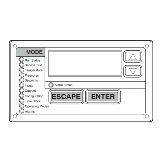
Page 70: Scrolling Marquee Display
4. The RJ14 CCN connector on CIB can also be used, but is only intended for temporary connection (for example, a C06321 Fig. 36 - - Accessory Navigatort Display laptop computer running Carrier network software). 5. Restore power to unit. Carrier Comfort Network (CCN) Interface IMPORTANT: A shorted CCN bus cable will prevent some routines from running and may prevent the unit from starting. -
Page 71: Energyx
UNIT BUILDING SUPERVISOR NETWORK ROOFTOP ROOFTOP OPTIONS UNIT UNIT LEGEND ® CCN -- Carrier Comfort Network ComfortLink Controls DAV -- Digital Air Volume HEATING/COOLING UNITS HVAC -- Heating, Ventilation, and Air Conditoning REMOTE AUTODIAL TCU -- Terminal Control Unit CCN SITE... -
Page 72: Protective Devices
If the use of one T-56 sensor is required, refer to Fig. 39. correct size fuse as indicated on the unit fuse label. Carrier Accessory Kits Saturated Suction Pressure (SSP) There are specific accessory kits sold for various field installed If the SSP for a particular circuit is reading below the alarm set point accessories. - Page 73 TB1-T55 TO MAIN BASE BOARD SENSOR 1 SENSOR 2 SENSOR 3 SENSOR 4 SPACE TEMPERATURE AVERAGING --4 T-55 SENSOR APPLICATION TB1-T55 TO MAIN BASE BOARD SENSOR 1 SENSOR 3 SENSOR 2 LEGEND -- Terminal Block ______ -- Factory Wiring _ _ _ _ -- Field Wiring SENSOR 4 SENSOR 5...
- Page 74 A SAT sensor in the supply duct is the preferred configuration for When installing either detector, the unit must be configured for fire systems with Carrier variable volume and temperature (VVT®) shutdown by setting Configuration→UNIT→FS.SW to normally accessory controls.
-
Page 75: Appendix A - Local Display And Ccn Tables
APPENDIX A — LOCAL DISPLAY AND CCN TABLES MODE — RUN STATUS CCN TABLE/ CCN WRITE ITEM EXPANSION RANGE UNITS CCN POINT Sub--- TABLE STATUS RUN STATUS STATUS DISPLAY VIEW Auto View of Run Status (VIEW = Display only) 1=Disabled 2=Ventilation HVAC HVAC Mode Status... - Page 76 APPENDIX A — LOCAL DISPLAY AND CCN TABLES MODE — RUN STATUS (cont) CCN TABLE/ CCN WRITE ITEM EXPANSION RANGE UNITS CCN POINT Sub--- TABLE STATUS ECON Economizer Status ECONDISP EC.CP Econo Commanded Position ECONOCMD EC.AP Econo Actual Position ECONOPOS EC.MP Min Position in Effect MIN_POS...
- Page 77 APPENDIX A — LOCAL DISPLAY AND CCN TABLES MODE — RUN STATUS (cont) CCN TABLE/ CCN WRITE ITEM EXPANSION RANGE UNITS CCN POINT Sub--- TABLE STATUS STRT Component Starts Compressor A1 Starts xxxxxx ST_A1 forcible Compressor B1 Starts xxxxxx ST_B1 forcible IDF1 Indoor Fan 1 Starts...
- Page 78 APPENDIX A — LOCAL DISPLAY AND CCN TABLES MODE — SERVICE TEST ITEM EXPANSION RANGE UNITS CCN TABLE/Sub--- TABLE CCN POINT SERVICE TEST TEST Field Service Test Mode Off/On (TEST = display only) INDP Test Independent Outputs TESTINDP ECON Economizer Position Test 0 to 100 S_ECONO E.CAL...
- Page 79 APPENDIX A — LOCAL DISPLAY AND CCN TABLES MODE — INPUTS DISPLAY CCN TABLE/ CCN WRITE ITEM EXPANSION RANGE UNITS CCN POINT WRITE Sub--- TABLE STATUS STATUS INPUTS STATUS DISPLAY STAT Thermostat Inputs UINPUT Thermostat Y1 Input Off/On forcible Thermostat Y2 Input Off/On forcible Thermostat W1 Input...
- Page 80 APPENDIX A — LOCAL DISPLAY AND CCN TABLES MODE — CONFIGURATION CCN TABLE/ PAGE ITEM EXPANSION RANGE UNITS DEFAULT CCN POINT Sub--- TABLE CONFIGURATION SERVICE CONFIGURATION DISP Display Configuration DISPLAY METR Metric Display Off/On DISPUNIT LANG Language Selection 0=English LANGUAGE 1=Spanish 2=French 3=Portuguese...
- Page 81 APPENDIX A — LOCAL DISPLAY AND CCN TABLES MODE — CONFIGURATION (cont) CCN TABLE/ PAGE ITEM EXPANSION RANGE UNITS DEFAULT CCN POINT Sub--- TABLE COOL Cooling Configuration COOL_CFG N.CIR Number of Circuits 0 to 3 1 (03--- 07) NUM_CIRC 2 (08--- 28) MRT.C Compressor Min On Time 120 to 999...
- Page 82 APPENDIX A — LOCAL DISPLAY AND CCN TABLES MODE — CONFIGURATION (cont) CCN TABLE/ PAGE ITEM EXPANSION RANGE UNITS DEFAULT CCN POINT Sub--- TABLE ECON Economizer Configuration ECON_CFG EC.EN Economizer Installed No/Yes No: no FIOP ECONO Yes: FIOP E.CTL Economizer Control Type 1=Dig/Position ECON_CTL 2=Dig/Command...
- Page 83 APPENDIX A — LOCAL DISPLAY AND CCN TABLES MODE — CONFIGURATION (cont) CCN TABLE/ PAGE ITEM EXPANSION RANGE UNITS DEFAULT CCN POINT Sub--- TABLE Outside Air Unit Config OAU_CFG OA.TY Outdoor Air Unit Type 0=No OAU 0: no FIOP OAU_TYPE 1=ERV Module 1: FIOP EnergyX 2=Economizer...
- Page 84 APPENDIX A — LOCAL DISPLAY AND CCN TABLES MODE — CONFIGURATION (cont) CCN TABLE/ PAGE ITEM EXPANSION RANGE UNITS DEFAULT CCN POINT Sub--- TABLE (GENERIC = GENERICS CCN only) POINT 01 Definition Point_01 POINT 02 Definition Point_02 POINT 03 Definition Point_03 POINT 04 Definition Point_04...
- Page 85 APPENDIX A — LOCAL DISPLAY AND CCN TABLES MODE — TIME CLOCK CCN TABLE/ ITEM EXPANSION RANGE UNITS DEFAULT CCN POINT Sub--- TABLE TIME CLOCK CONFIGURATION TIME Time of Day TIME TIME Hour and Minute xx.xx hh.mm TIME DATE Current Date MNTH Month of Year January, February, ...,...
- Page 86 APPENDIX A — LOCAL DISPLAY AND CCN TABLES MODE — OPERATING MODES DISPLAY CCN TABLE/ ITEM EXPANSION RANGE UNITS CCN POINT WRITE WRITE Sub--- TABLE STATUS STATUS OPERATING MODES MAINTENANCE DISPLAY MODE Control Modes MODES Unit operation disabled SYS_MODE_TEXT1 Unit operation enabled SYS_MODE_TEXT2 Service test enabled (table only)
- Page 87 APPENDIX A — LOCAL DISPLAY AND CCN TABLES MODE — OPERATING MODES (cont) DISPLAY CCN TABLE/ ITEM EXPANSION RANGE UNITS CCN POINT WRITE WRITE Sub--- TABLE STATUS STATUS COOL (cont) Cool Mode Diagnostic COOLDIAG R.LP .B Reheat2 SSP Override B No/Yes RHBLPOV AVL.R...
- Page 88 APPENDIX A — LOCAL DISPLAY AND CCN TABLES MODE — OPERATING MODES (cont) DISPLAY CCN TABLE/ ITEM EXPANSION RANGE UNITS CCN POINT WRITE WRITE Sub--- TABLE STATUS STATUS Outside Air Unit Diagnostic OAU_DIAG OA.RN OAU System Run State 1=AUTO OAU_RUN 2=OFF 3=TEST OA.OP...
- Page 89 APPENDIX A — LOCAL DISPLAY AND CCN TABLES MODE — OPERATING MODES (cont) DISPLAY CCN TABLE/ ITEM EXPANSION RANGE UNITS CCN POINT WRITE WRITE Sub--- TABLE STATUS STATUS (LINKDATA = CCN --- Linkage LINKDATA only) Supervisory Element # SUPE--- ADR Supervisory Bus SUPE--- BUS Supervisory Block Number...
-
Page 90: Appendix B - - Control Modes With Humidi- -Mizert System And Economizer
APPENDIX B — CONTROL MODES WITH Humidi- -MiZer™ SYSTEM AND ECONOMIZER Thermostat input shown for cooling demand (versus temperature Circuit Subcooling mode = REHEAT 1 sensor point). Humidistat input shown Circuit HGRH mode = hot gas reheat = REHEAT 2 dehumidification demand (versus relative humidity sensor and set Circuit ON mode = normal cooling point). -
Page 91: Appendix C - - Variable Frequency Drive
Failure to follow this caution may result in damage to the unit or in degradation of unit performance. TERMINALS Do not run the Carrier Assistant through the VFD keypad. 28 – 31 This will cause parameters to change value that are not desired on these applications. - Page 92 Table 27 – VFD Parameters Configured by Factory or VFD Keypad Parameter Group Parameter Title ABB Parameter HVAC Default CARRIER Options COMM PROT SEL 9802 NOT SEL LEN (6) EFB PROTOCOL ID 5301 0000 hex 0601 hex EFB STATION ID...
- Page 93 Table 31 – VFD Motor Default Configurations UNIT COMFORTLINK CCN POINT (DISPLAY MENU ITEM) UNIT SIZE UNIT VOLTAGE STATIC (Digits VFD1NVLT VFD1NAMP VFD1NFRQ VFD1NRPM VFD1NPWR VFD1MAXA (Digit 12) OPTION 7 & 8) (N.VLT) (N.AMP) (N.FRQ) (N.RPM) (N.PWR) (MAX.A) (Digit 10)* Low (1) 60Hz 1725...
- Page 94 Table 31 — VFD Motor Default Configurations (cont) UNIT COMFORTLINK CCN POINT (DISPLAY MENU ITEM) UNIT SIZE UNIT VOLTAGE STATIC (Digits VFD1NVLT VFD1NAMP VFD1NFRQ VFD1NRPM VFD1NPWR VFD1MAXA (Digit 12) OPTION 7 & 8) (N.VLT) (N.AMP) (N.FRQ) (N.RPM) (N.PWR) (MAX.A) (Digit 10)* V--- Low (1) 11.7 60Hz...
- Page 95 VFD Diagnostics Alarm messages disappear from the control panel display after a few seconds. The message returns periodically as long as the alarm The drive detects error situations and reports them using: condition exists. 1. Green and red LEDs on the body of the drive (located under Correcting Faults the keypad) The recommended corrective action for faults is shown in the Fault...
- Page 96 3015 UNDERLOAD CURVE. THERM FAIL Internal fault. The thermistor measuring the internal temperature of the drive is open or shorted. Contact Carrier. Internal fault. A communication ---related problem has been detected between the OMIO and OINT boards. Contact OPEX LINK Carrier.
- Page 97 Table 32 — FAULT CODES (cont) FAULT FAULT NAME IN PANEL DESCRIPTION AND RECOMMENDED CORRECTIVE ACTION CODE 1008 Parameter values are inconsistent. The 9904 MOTOR CTRL MODE must = 3 (SCALAR SPEED) when 8123 PFA PAR PFA MODE ENABLE activated. 1009 Parameter values for power control are inconsistent or improper motor nominal frequency or speed.
-
Page 98: Control Set Point And Configuration Log
CONTROL SET POINT AND CONFIGURATION LOG MODEL NO.: SOFTWARE VERSIONS SERIAL NO.: MBB: CESR131504- -- -_ _ DATE: ECB: CESR131249- -- -_ _ TECHNICIAN: MARQ: CESR131171- -- -_ _ INDICATE UNIT SETTINGS BELOW CONTROL TYPE: Thermostat/T55 Space Temp./T- -56 Space Temp./T- -58 Space Temp. SET POINT Cooling Occupied:... - Page 99 MODE — CONFIGURATION (cont) CCN TABLE/ ITEM EXPANSION RANGE UNITS DEFAULT CCN POINT ENTRY Sub---TABLE I.FAN INDOOR FAN CONFIG FAN_CFG FTYP Indoor Fan Type 0=1--- SPEED FAN_TYPE 1=LEN VFD 1: SAV option 2=ECM 3=DI VFD 4=AI VFD NSPD Number of Speeds 2=TWO NUM_SPDS 3=THREE...
- Page 100 MODE — CONFIGURATION (cont) CCN TABLE/ ITEM EXPANSION RANGE UNITS DEFAULT CCN POINT ENTRY Sub---TABLE HMZR Humidimizer Config HMZR_CFG REHT Humidimizer Equipped No/Yes No: no Humidi--- MiZer FIOP REHEAT Yes: Humidi--- MiZer FIOP R.DEC Reheat2 Stage Decr. Time 0 to 999 secs RSTAGDEC R.INC...
- Page 101 MODE — CONFIGURATION (cont) CCN TABLE/ ITEM EXPANSION RANGE UNITS DEFAULT CCN POINT ENTRY Sub---TABLE AIR.Q Air Quality Config. IAQ_CFG IA.CF IAQ Analog Input Config 0=No IAQ 0: no FIOP IAQANCFG 1=DCV 1: FIOP 2=Override IAQ 3=Ctrl Min Pos IA.FN IAQ Analog Fan Config 0=Never IAQANFAN...
- Page 102 MODE — CONFIGURATION (cont) CCN TABLE/ ITEM EXPANSION RANGE UNITS DEFAULT CCN POINT ENTRY Sub---TABLE OAU (cont) Outside Air Unit Config OAU_CFG TM.SP OA Tempring SAT Setpoint 35 to 80 OATMPSPT OAC.K Outside Air CFM k Factor 0.8 to 1.2 OACFM_K EXC.K Exhaust Air CFM k Factor...
- Page 103 MODE — CONFIGURATION (cont) CCN TABLE/ ITEM EXPANSION RANGE UNITS DEFAULT CCN POINT ENTRY Sub---TABLE SCH.O CCN Schedule Overrides SCHEDOVR SCH.N Schedule Number 0 = Always Occupied SCHEDNUM 1--- 64 = Local Schedule 65--- 99 = Global Schedule HOL.G Accept Global Holidays No/Yes HOLIDAYT OV.TL...
-
Page 104: Unit Start-Up Checklist
VERIFY REFRIGERANT CHARGE USING CHARGING CHARTS GENERAL ECONOMIZER MINIMUM VENT AND CHANGEOVER SETTINGS TO JOB REQUIREMENTS Catalog No: 48---50HC ---C02T Copyright 2012 Carrier Corp. S 7310 W. Morris St. S Indianapolis, IN 46231 Printed in U.S.A. Edition Date: 05/12 Replaces: 48--- 50HC--- C01T...