Bryant 588A Manual
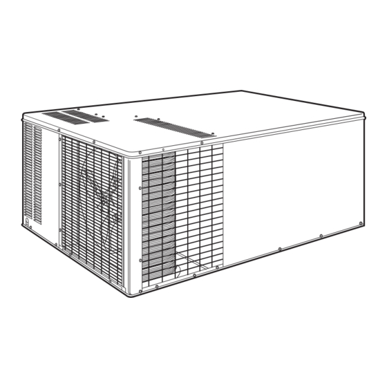
Single package
gas heating/
electric cooling units
Hide thumbs
Also See for 588A:
- User manual (27 pages) ,
- Installation, start-up and service instructions manual (53 pages)
Table of Contents
Advertisement
Quick Links
Bryant
Air Conditioning
DESCRIPTION
All 588A models feature one piece, compact design and are fully
self-contained units that are prewired, prepiped, and pre-
charged for minimum installation expense. Unit is designed for
easy use in either downflow (vertical) or horizontal applications.
STANDARD FEATURES
FACTORY-ASSEMBLED PACKAGE is a compact, fully self-
contained, gas heating/electric cooling unit that is prewired, pre-
piped, and precharged for minimum installation expense.
588A units are lightweight and available in a variety of standard
heating and cooling sizes with voltage options to meet residen-
tial and light commercial requirements. Unit installs easily on a
rooftop or a ground-level pad.
CONVERTIBLE DUCT CONFIGURATION on the 588A is de-
signed for easy use in either downflow or horizontal discharge
applications.
HIGH-EFFICIENCY DESIGN with SEERs (Seasonal Energy Ef-
ficiency Ratios) of 10.0.
DURABLE, DEPENDABLE COMPRESSORS are designed for
high efficiency. Each compressor is hermetically sealed against
contamination to help promote longer life and dependable op-
eration. Each compressor also has vibration isolation to provide
quiet operation. Rotary, reciprocating, or scroll compressors are
used. Compressors have internal high-pressure and overcur-
rent protection.
TOP QUALITY, TOP RELIABILLITY components, designed
and treated for a minimum of 15 years of operation under the
harshest conditions. Every 588A unit is thoroughly run-tested at
the factory in each operating mode, and is evacuated prior to fi-
nal charging.
DIRECT-DRIVE
MULTISPEED,
Capacitor) BLOWER MOTOR is standard on all models.
DIRECT-DRIVE, PSC CONDENSER-FAN MOTOR is designed
to help reduce energy consumption and provide for cooling op-
eration down to 40 F.
SINGLE PACKAGE
GAS HEATING/
ELECTRIC COOLING UNITS
PSC
(Permanent
Split
REFRIGERANT SYSTEM is designed to provide dependability.
Liquid refrigerant strainer is used to promote clean, unrestricted
operation. Each unit leaves the factory with a full refrigerant
charge. Refrigerant service connections make checking operat-
ing pressures easier.
EVAPORATOR AND CONDENSER COILS are computer-
designed for optimum heat transfer and cooling efficiency. Con-
denser coil is fabricated of copper tube and aluminum fins and
is located inside the unit for protection against damage and for
long life and reliable operation. The condenser coil is internally
mounted and protected by a composite grille.
Copper fin coils for condenser coil are also available by special
order. These coils are recommended in applications where alu-
minum fins are likely to be damaged due to corrosion. Copper
fin coils are ideal for seacoast applications.
DIMPLED HEAT EXCHANGERS optimize heat transfer for im-
proved efficiency. The tubular design permits hot gases to stay
in close contact with the cell walls to maximize heat transfer and
efficiency.
THE INDUCED DRAFT COMBUSTION SYSTEM eliminates
the unsightly appearance of flue stacks, and diminishes the ef-
fects of wind on heating operation. The induced draft also pre-
vents contaminants from entering the supply air if a leak in the
heat exchanger occurs.
MONOPORT INSHOT BURNERS produce precise air-to-gas
mixture, which provides for clean and efficient combustion. The
large monoport on the inshot (or injection type) burners seldom,
if ever, needs cleaning.
INTEGRATED GAS UNIT CONTROLLER (IGC) contains all
the ignition components and is easily accessible for service.
The IGC provides built-in diagnostic capabilities. A light-emitting
diode (LED) simplifies troubleshooting by providing visual fault
notification and system status information. The IGC board pro-
vides exclusive anti-short cycle protection for gas heat opera-
tion. The IGC also contains burner control logic for dependable
heating operation. The 588A units maximize heating efficiency
through the IGC's control of evaporator fan ON/OFF delays.
The IGC helps make 588A units reliable for many years.
WEATHERIZED CABINETS are constructed of heavy-duty,
phosphated, zinc-coated prepainted steel capable of withstand-
ing 500 hours (Federal Test Method Std. No. 141, Method 6061)
in salt spray. Interior surfaces of the evaporator compartment
are insulated with cleanable foil-faced insulation to help keep
the conditioned air from being affected by the outdoor ambient
temperature and provide improved air quality. Conforms to
American Society of Heating, Refrigeration and Air Conditioning
Engineers (ASHRAE) No. 62. Sloped condensate pan requires
external drain trap.
LOW SOUND RATINGS ensure a quiet indoor and outdoor en-
vironment with sound ratings as low as 7.4 bels.
EASY TO SERVICE CABINETS provide easy accessibility to
serviceable components during maintenance and installation.
Rounded corners are an important safety feature, and a high-
quality finish ensures an attractive appearance.
Form No. PDS 588A.18.5B
Model 588A
Sizes 018-060
1
⁄
to 5 Tons
1
2
Advertisement
Table of Contents

Related Manuals for Bryant 588A


Summary of Contents for Bryant 588A
- Page 1 DESCRIPTION proved efficiency. The tubular design permits hot gases to stay All 588A models feature one piece, compact design and are fully in close contact with the cell walls to maximize heat transfer and self-contained units that are prewired, prepiped, and pre- efficiency.
- Page 2 Ideal for light com- mercial applications. STANDARDIZED COMPONENTS for the complete 588A line of products are found in all safety devices, condenser-fan motors, FACTORY-INSTALLED OPTIONS DESCRIPTION AND USAGE Unit With Base Rail — Unit has rigging and forklift holes and Downflow Option —...
-
Page 3: Table Of Contents
FIELD-INSTALLED ACCESSORY DESCRIPTION AND CONTENTS USAGE (cont) Page Model Description ....... . . 3 Lifting Bracket Kit —... -
Page 4: Ari Cooling Capacities
ARI* COOLING CAPACITIES NOMINAL STANDARD NET COOLING† SOUND RATINGS†† UNIT 588A SEER†** TONS CAPACITIES (Btuh) (Bels) ⁄ 17,000 10.0 24,000 10.0 ⁄ 1000 29,200 10.0 1200 36,000 10.0 ⁄ 1400 42,500 10.0 1600 47,000 10.0 1995 59,500 10.0 LEGEND ††Rated in accordance with ARI Standard 270. -
Page 5: Dimensional Drawings
DIMENSIONAL DRAWINGS CENTER OF GRAVITY in./mm UNIT in./mm in./mm 588A018040 25.07/637 20.59/523 588A024040 27.07/688 23.35/593 588A024060 26.98/685 23.27/591 588A030040 ⁄ /420.7 ⁄ /481.0 26.71/678 23.46/596 10.85/276 588A030060/080 27.15/689 22.36/568 588A036060/080 27.50/698 22.48/571 588A036100/120 27.40/696 22.44/570 588A042060/080 27.01/686 22.44/570 ⁄ /522.3 ⁄... - Page 6 DIMENSIONAL DRAWINGS (cont) CENTER OF GRAVITY in./mm UNIT in./mm in./mm 588A018040 25.04/636 22.72/577 588A024040 26.90/683.3 20.17/512.3 588A024060 26.82/681.2 20.22/513.6 588A030040 ⁄ /504.8 22 ⁄ /565.4 26.57/674.9 20.1 /509.3 13.16/334.3 588A030060/080 26.93/684 21.1 /535.4 588A036060/080 27.31/693.7 21.0 /532.6 588A036100/120 27.23/691.6 21.0 /533.1 588A042060/080 26.87/682.5 21.0 /533.1 ⁄...
- Page 7 DIMENSIONAL DRAWINGS (cont) REQ’D CLEARANCES FOR SERVICING. in. (mm) Duct panel ........0 Unit top .
- Page 8 DIMENSIONAL DRAWINGS (cont) REQ’D CLEARANCES FOR SERVICING. in. (mm) Duct panel ........0 Unit top .
- Page 9 DIMENSIONAL DRAWINGS (cont) UNIT PART NUMBER ‘‘A’’ CPRFCURB001A00 8 [203] 588A CPRFCURB002A00 11 [279] CPRFCURB003A00 14 [356] NOTES: 1. Roof curb must be set up for unit being installed. 2. Seal strip must be applied as required for unit being installed.
- Page 10 DIMENSIONAL DRAWINGS (cont) Manual Outdoor-Air Damper ACCESSORY PART NUMBER ‘‘A’’ CPFILTRK001A00 ⁄ FILTER CPFILTRK002A00 ⁄ RACK CPFILTRK003A00 ⁄ Filter Racks and Filters...
-
Page 11: Specifications
SPECIFICATIONS UNIT SIZE 588A 018040 024040 024060 030040 030060 030080 NOMINAL CAPACITY (tons) ⁄ ⁄ ⁄ ⁄ OPERATING WEIGHT (lb) Without Base Rail With Optional Base Rail COMPRESSOR Type Rotary Reciprocating Quantity REFRIGERANT R-22 Charge (lb) 2.60 2.75 2.75 3.40 3.40... - Page 12 SPECIFICATIONS (cont) UNIT SIZE 588A 042100 042120 048080 048100 048120 048140 NOMINAL CAPACITY (tons) ⁄ ⁄ OPERATING WEIGHT (lb) Without Base Rail With Optional Base Rail COMPRESSOR Type Reciprocating Hermetic Scroll Quantity REFRIGERANT R-22 Charge (lb) 5.20 5.20 6.50 6.50 6.50...
-
Page 13: Selection Procedure
SELECTION PROCEDURE I DETERMINE COOLING AND HEATING REQUIRE- IV DETERMINE FAN SPEED AND POWER REQUIRE- MENTS AT DESIGN CONDITIONS: MENTS AT DESIGN CONDITIONS. Given: Before entering the air delivery tables, calculate the total static pressure required. From the given, the Wet Coil Required Cooling Capacity (TC) . -
Page 14: Net Cooling Capacities
NET COOLING CAPACITIES 588A018 (1 ⁄ TONS) Outdoor Coil Entering-Air Temperature (F) Indoor Coil Air Capacity Capacity Capacity Capacity Total Total Total Total (Btuh x 1000) (Btuh x 1000) (Btuh x 1000) (Btuh x 1000) System System System System Total Sensible Total Sensible... - Page 15 NET COOLING CAPACITIES (cont) 588A036 (3 TONS) Outdoor Coil Entering-Air Temperature (F) Indoor Coil Air Capacity Capacity Capacity Capacity Total Total Total Total (Btuh x 1000) (Btuh x 1000) (Btuh x 1000) (Btuh x 1000) System System System System Total Sensible Total Sensible...
-
Page 16: Net Cooling Capacities
NET COOLING CAPACITIES (cont) 588A060 (5 TONS) Outdoor Coil Entering-Air Temperature (F) Indoor Coil Air Capacity Capacity Capacity Capacity Total Total Total Total (Btuh x 1000) (Btuh x 1000) (Btuh x 1000) (Btuh x 1000) System System System System Total Sensible Total Sensible... -
Page 17: Air Delivery
DRY COIL AIR DELIVERY* — HORIZONTAL DISCHARGE (Deduct 10% for 208 v) 230 AND 460 VOLT HORIZONTAL DISCHARGE UNIT MOTOR SIZE External Static Pressure (in. wg) SPEED 588A Watts — — — — — — — — — — Watts —... -
Page 18: Air Delivery
DRY COIL AIR DELIVERY* — VERTICAL DISCHARGE (Deduct 10% for 208 v) 230 AND 460 VOLT VERTICAL DISCHARGE UNIT MOTOR SIZE External Static Pressure (in. wg) SPEED 588A Watts — — — — — — — — Watts — —... - Page 19 WET COIL PRESSURE DROP UNIT SIZE AIRFLOW PRESSURE DROP 588A (cfm) (in. wg) 0.069 0.082 0.102 0.116 0.039 0.058 0.075 0.088 0.088 1000 0.095 1200 0.123 1000 0.068 1200 0.088 1400 0.108 1600 0.123 1000 0.048 1200 0.069 1400 0.088 1600 0.102...
-
Page 20: Electrical Data
ELECTRICAL DATA COND. VOLTAGE INDOOR AWG 60 C MAX WIRE COMPRESSOR POWER SUPPLY UNIT RANGE V-PH-Hz MIN WIRE LENGTH MOTOR 588A SIZE (ft) MOCP* 208/230-1-60 12.0 208/230-1-60 12.4 18.2 208/230-1-60 14.4 21.8 208/230-3-60 15.5 208/230-1-60 18.0 26.7 208/230-3-60 11.7 18.8... -
Page 21: Operating Sequence
OPERATING SEQUENCE HEATING The normally-open contacts of energized contactor (C) close and complete the circuit through compressor motor (COMP) On a call for heating, terminal ‘‘W’’ of the thermostat is ener- and condenser (outdoor) fan motor (OFM). Both motors start gized, starting the induced-draft motor. -
Page 22: Typical Field Wiring
TYPICAL FIELD WIRING LEGEND — American Wire Gage — Outdoor-Fan Motor — Blower Relay — Power — Contactor — Quadruple Terminal — Capacitor — Rollout Switch — Crankcase Heater TRAN — Transformer COMP — Compressor Motor Field Splice — Combustion Relay EQUIP —... - Page 23 TYPICAL FIELD WIRING (cont) LEGEND — American Wire Gage — Outdoor-Fan Motor — Blower Relay — Power — Contactor — Quadruple Terminal — Capacitor — Rollout Switch — Crankcase Heater TRAN — Transformer COMP — Compressor Motor Field Splice — Combustion Relay EQUIP —...
- Page 24 TYPICAL FIELD WIRING (cont) LEGEND — American Wire Gage — Power — Blower Relay — Quadruple Terminal — Contactor — Rollout Switch — Capacitor TRAN — Transformer — Crankcase Heater Field Splice COMP — Compressor Motor — Combustion Relay Terminal (Marked) EQUIP —...
-
Page 25: Typical Installation
TYPICAL INSTALLATION Power Wiring Control Wiring Outdoor Airflow Indoor Airflow NEC — National Electrical Code Horizontal Discharge ROOF-MOUNTING CURB ROOF RETURN-AIR FLEXIBLE DUCT SUPPLY-AIR FLEXIBLE DUCT CEILING Downflow Discharge... -
Page 26: Application Data
APPLICATION DATA 1. Condensate trap — A 2-in. condensate trap must be field 3. Airflow — Units are draw-thru on cooling and blow-thru on supplied. heating. 2. Ductwork — Secure downflow discharge ductwork to roof 4. Maximum cooling airflow — To minimize the possibility of curb. -
Page 28: Air Conditioning
SPECIFICATIONS SUBJECT TO CHANGE WITHOUT NOTICE Bryant UNIT MUST BE INSTALLED IN ACCORDANCE Air Conditioning WITH INSTALLATION INSTRUCTIONS Copyright 1997 Carrier Corporation Printed in U.S.A. 2/97 CATALOG NO. BY-3258-804...