Advertisement
Advertisement
Table of Contents

Related Manuals for Casio AP-10


Summary of Contents for Casio AP-10
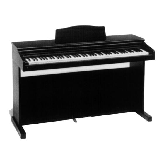
- Page 1 (with price) AP-10 ELECTRONIC KEYBOARD...
-
Page 2: Table Of Contents
CONTENTS Safety Notice ..................2 Specifications ..................3 Block Diagram ..................4 PCB Layout ..................5 Disassembly Instructions ..............6 Circuit Description ................10 Major Waveforms ................12 Troubleshooting ................13 Wiring Diagram ................17 Exploded View .................. 18 Parts List ................... 21 Schematic Diagrams ............... 23 SAFETY NOTICE CAUTION! Danger of explosion if battery is incorrectly replaced. -
Page 3: Specifications
Weight: Without stand: 25.0 kg (55.1 lbs)/28.0 kg (61.7 lbs) With stand: 35.5 kg (78.3 lbs)/38.5 kg (84.9 lbs) Note: There are two models of AP-10, one has a keyboard cover, the other has no keyboard cover. — 3 —... -
Page 4: Block Diagram
BLOCK DIAGRAM Working Storage MIDI RAM (64K-bit) Buttons LSI304 LC3564SM-85 KI0 ~ KI2 FI0 ~ FI10 SI0 ~ SI19 MA12 Keyboard Sound Source ROM MD0 ~ MD15 (8M-bit) LSI301 KC0 ~ KC7 LSI303 MX23C8100MC- UPD912GF-3BA MA1 ~ MA19 12CA27 Reset IC IC 302 RN5VD24AA MA0, MA1... -
Page 5: Pcb Layout
PCB LAYOUT PS1M PS2M MA1M PS3M VOLUME TRANSPOSE/ DIGITAL TONE MEMORY DEMO TUNE/MIDI EFFECT CN1M CHORUS REVERB SONG A START/ AP-10 HARPSI- PIPE REVERB2 STOP SONG B PIANO E.PIANO CHORD ORGAN STRINGS RECORD REVERB1 POWER TP8-KY1M TP8-KY2M PS4M JCM358- Components... -
Page 6: Disassembly Instructions
DISASSEMBLY INSTRUCTIONS 1. Disassembling top board 1-1. Remove 8 screws on the rear. 1-2. Slide the top board towards the rear. The top board will be free from catches on the case. 1-3. Lift the top board. For keyboard-cover model 2. - Page 7 3. Disassembling the console panel Note: To avoid scratch on the side board, put paper between the console panel and the side board at both ends. 3-1. The console panel is fixed with screws and nuts. Holding the nut, remove the screw. 3-2.
- Page 8 5. Disassembling keys 5-1. Remove a key spring. 5-2. Use a long-nose plier, pressing the hook, lift the key. Apply grease G501 6. Disassembling keyboard PCBs 6-1. Turn around the keyboard unit to face the PCB up. 6-2. Disconnect the connector at middle of the keyboard. 6-3.
- Page 9 7. Replacing the main PCB Note: The main PCB contains a lithium battery for memory back-up. Please remove the jumper before replacing the PCB. And make sure that the jumper is reset on new main PCB after replacing the PCB. Because no jumper is set on a spare part of the main PCB.
-
Page 10: Circuit Description
CIRCUIT DESCRIPTION KEYMATRIX Second contact First contact UPD912GF-3BA A0 1 A0 # 1 B0 1 C1 1 C1 # 1 D1 1 D1 # 1 E1 1 A0 2 A0 # 2 B0 2 C1 2 C1 # 2 D1 2 D1 # 2 E1 2 F1 1... - Page 11 POWER SUPPLY CIRCUIT The power supply circuit generates five voltages as shown in the following table. Name Voltage For operation of +5 V CPU, Reset IC, DSP, Sound source ROM, Working storage RAM, Effect RAM, LEDs AVDD +5 V LVDD +5 V Power lamp AVCC +12.5 V...
-
Page 12: Major Waveforms
MAJOR WAVEFORMS A .5 s A 1ms ˜ ˜ CH1 .2V CH2 .2V 1 VDD CA connector pin 6 4 DAC output CA connector pin 1 2 NMI CA connector pin 8 5 DAC output CA connector pin 2 3 POWER CA connector pin 9 A 1ms A 20µs... -
Page 13: Troubleshooting
TROUBLESHOOTING No power Check fuse F101. Is F101 blown up? Replace F101. Check fuse F102. Is F102 blown up? Replace F102. Measure output voltage of transformer T101. • Check power switch. Is voltage 14 V AC? • Check position of voltage selector. - Page 14 No sound Press "Hall" button. Follow from (A) of "No sound" Does the LED light up? troubleshooting. Measure voltage at pin 9 of CA connector. Is the voltage +5 V? Set main volume to maximum. Touch pin1 of CA connector with test rod (+) of multimeter in resistance range, connecting test rod (-) to ground.
- Page 15 Distorted sound Replace PS2M PCB. Is a sound ok? Replace MA1M PCB. Certain keys do not function Replace MA1M PCB. Do the keys function? Replace keyboard PCBs. A certain key does not function Clean the contact. Does the key function? Replace key contact rubber.
- Page 16 A certain button does not function Replace CN1M PCB. Does the button function? Replace MA1M PCB. — 16 —...
-
Page 17: Wiring Diagram
WIRING DIAGRAM POWER Lamp Speakers PHONES Left JCM358-PS3M CM-1 LVDD CM-1 CM-2 CM-2 Right JCM358-PS4M MIDI IN OUT JCM358-PS1 TRANSFORMER TRANS TRANS CF-1 Lmel OUT CF-R-O JCM358-PS2M CF-2 Rmel OUT CF-R-Y CF-3 CF-R-E CF-4 Lmel IN CF-R-BR POWER CF-5 Rmel IN CF-R-R Switch PEDAL... -
Page 18: Exploded View
EXPLODED VIEW STAND R-10 R-11 R-11 — 18 —... -
Page 20: Parts List
PARTS LIST AP-10 Notes: This parts list does not include the cosmetic parts, which parts are marked with item No. "R-X" in the exploded view. Contact our spare parts department if you need these parts for refurbish. Prices and specifications are subject to change with- out prior notice. - Page 21 FOB Japan Item Code No. Parts Name Specification N.R.Yen Unit Price Main PCB BT301 3815 0714 Lithium battery CR1220/1VC D301 2390 2555 Chip schottky diode RB500V-40TE-17 IC302 2105 5173 MOS IC RN5VD42AA-TR LSI301 2012 2072 LSI UPD912GF-3BA(T) LSI302 2012 2079 LSI HG51B227FB-1 LSI303 2012 1890 LSI...
- Page 22 M311405A-1 6924 5240 Button set 358 M240303*1 Stand 6924 6670 Pedal box ass'y A190007200 3,920 6924 7100 Screw set for AP-10's stand A190007300 AC cord 3701 0196 AC cord (120V, USA) UC-964-J01 3701 0595 AC cord (230V, Europe) EC-654-E06 3701 0588 AC cord (230V, UK)
-
Page 23: Schematic Diagrams
SCHEMATIC DIAGRAMS MAIN PCB (A) JCM358-MA1M D/A Converter Sound Source Working Storage Reset IC Effect RAM — 23 —... - Page 24 MAIN (B) & POWER SUPPLY PCBs JCM358-PS1/PS2M/PS3M/PS4M Power Amp.
- Page 25 CONSOLE PCB JCM358-CN1M CHORUS REVERB REVERB2 REVERB1 — 25 —...
- Page 26 KEYBOARD PCB TP8-KY1 — 26 —...
- Page 27 KEYBOARD PCB TP-KY2 — 27 —...
- Page 28 8-11-10, Nishi-Shinjuku Shinjuku-ku, Tokyo 160, Japan Telephone: 03-3347-4926 MA0100661A...