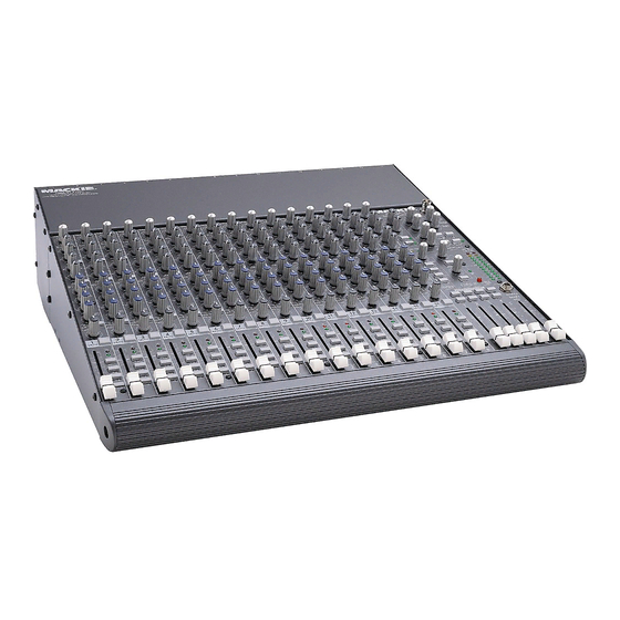
Mackie 1604-vlz Service Manual
16ch mic/line mixer
Hide thumbs
Also See for 1604-vlz:
- Owner's manual (51 pages) ,
- Bedienungsanleitung (44 pages) ,
- Service manual (19 pages)
Advertisement
Table of Contents
Advertisement
Table of Contents

Summary of Contents for Mackie 1604-vlz
- Page 1 Block Diagram open that page Channel Schematic Pod Section Schematics Pod Section PCB Layout Main Section Schematics 9-14 Main Section PCB Layout Jumper Location and Pinout Power Supply MACKIE DESIGNS INC., 16220 WOOD-RED ROAD, WOODINVILLE, WA 98072, USA 820-172-00 05/99...
- Page 2 POD COMPONENTS... TRIM AUX RETURNS QUICK PARTS ALL 1/4"JACKS knob 760-048-01 knob 760-048-01 BNC JACK jack 400-214-00 pot 130-030-02 pot 130-061-02 400-010-00 washer710-00200 nut 705-003-00 FEMALE XLR INP UT AUX SEND MSTRS 400-223-00 AUX S ENDS EFFECTS TO MON knob 760-048-01 RCA IN/OUT knob 760-048-02 knob 760-048-01...
- Page 3 SUBMIX 2 (SUBMIX 4 LEVEL ASSIGN TO IDENTICAL) C-R/PHNS ONLY SIP L AUX SEND 1 (#2 IDENTICAL) SOLO SIP R MACKIE CR1604-VLZ MACKIE CR1604-VLZ AUX 1 OUT SOLO LEVEL SIGNAL FLOW SIGNAL FLOW AUX MIX 16-1127.VSD 16-1127.VSD AUX SEND 3 (#4 - 6...
- Page 4 CR1604-VLZ, CHANNEL...
- Page 5 CR1604-VLZ, POD SECTION SHEET 1...
- Page 6 CR1604-VLZ, POD SECTION, SHEET 2...
- Page 7 CR1604-VLZ POD SECTION, SHEET 3...
- Page 8 REV C CR1604-VLZ POD PCB LAYOUT, LEFT HALF...
- Page 9 REV C CR1604-VLZ POD PCB LAYOUT, RIGHT HALF...
- Page 10 1604-VLZ MAIN SECTION, SHEET 1...
- Page 11 CR1604-VLZ MAIN SECTION, SHEET 2...
- Page 12 CR1604-VLZ MAIN SECTION, SHEET 3...
- Page 13 CR1604-VLZ MAIN SECTION, SHEET 4...
- Page 14 CR1604-VLZ MAIN SECTION, SHEET 5...
- Page 15 CR1604-VLZ MAIN SECTION, SHEET 6...
- Page 16 ™ CR1604-VLZ MAIN BOARD PCB LAYOUT REV B CHANNELS 3-14 NOT SHOWN, REFFER TO CHANNELS 1-2.
- Page 17 CHANNEL 1 GND 1 2 CHANNEL 1 TRIM A ™ CHANNEL 1 GND 3 4 CHANNEL 1 TRIM B CHANNEL 1 GND 5 6 CHANNEL 1 IN 40 PIN MAIN CABLE PART # 040-076-00 CHANNEL 1 GND 7 8 CHANNEL 1 DI OUT POD CABLE PART # 040-073-00 CHANNEL 2 GND 9 10 CHANNEL 2 TRIM A CR1604-VLZ...
- Page 18 ‰ CR1604-VLZ POWER SUPPLY...
- Page 19 1604-VLZ Auxiliary modifications In addition to the modifications shown in the 1604-VLZ owner’s manual, there are two rather lovely and optional mods for the signal routing of Aux 3/4 and 5/6. UL Warning CAUTION! These modification instructions are for use by qualified personnel only. To avoid electric shock, do not perform any servicing other than changing the fuse unless you are qualified to do so.
- Page 20 THE MACKIE FIXER • MACKIE DESIGNS SERVICE NEWS To make Aux 3/5 and Aux4/6 To make Aux 3/5 and Aux4/6 Pre-EQ and Pre-Fader Post-EQ and Pre-Fader Aux 3/5 Aux 3/5 1. Cut the trace between the round and 1. Cut the trace between the round and...
- Page 21 THE MACKIE FIXER • MACKIE DESIGNS SERVICE NEWS 1604-VLZ Aux mod, sheet 3 of 3...


