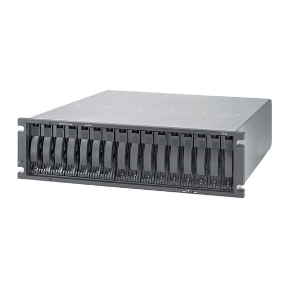
IBM DS4700 Installation, User's, And Maintenance Manual
Express storage subsystem
Hide thumbs
Also See for DS4700:
- Product manual (8 pages) ,
- Overview (8 pages) ,
- Hardware manual (566 pages)

Related Manuals for IBM DS4700


Summary of Contents for IBM DS4700
- Page 1 IBM System Storage DS4700 Express Storage Subsystem Installation, User’s and Maintenance Guide GC26-7843-05...
- Page 3 IBM System Storage DS4700 Express Storage Subsystem Installation, User’s and Maintenance Guide GC26-7843-05...
- Page 4 Before using this information and the product it supports, be sure to read the general information in the “Safety” on page xv and “Notices” on page 215 sections. Sixth Edition (November 2011) © Copyright IBM Corporation 2010. US Government Users Restricted Rights – Use, duplication or disclosure restricted by GSA ADP Schedule Contract with IBM Corp.
-
Page 5: Table Of Contents
Shock and vibration requirements ....26 Acoustic noise ..... . . 26 © Copyright IBM Corp. 2010... - Page 6 Installing the support rails ..... 36 Installing the DS4700 Express ....40 Removing the CRUs .
- Page 7 ..... 78 One DS4700 Express and one EXP100 storage expansion enclosure. . . 80 One DS4700 Express and two EXP100 storage expansion enclosures One DS4700 Express and three or more EXP100 storage expansion enclosures.
- Page 8 DS4800 Storage Subsystem library ....204 DS4700 Storage Subsystem library ....205 DS4500 Storage Subsystem library .
- Page 9 Important notes ......216 Particulate contamination..... 217 Documentation format .
- Page 10 IBM System Storage DS4700 Express Storage Subsystem: Installation, User’s and Maintenance Guide...
-
Page 11: Figures
14. DS4700 Express dimensions ......23 15. DS4700 Express airflow ......25 16. - Page 12 65. One DS4700 Express and a maximum of six EXP100 storage expansion enclosures behind a pair of DS4700 drive ports ......84 66.
- Page 13 119. Screws holding the top and bottom sides of the chassis to the cage frame ..181 120. DS4700 Express Storage Subsystem parts list ....189 121.
- Page 14 IBM System Storage DS4700 Express Storage Subsystem: Installation, User’s and Maintenance Guide...
-
Page 15: Tables
9. Filter and filter retainer description ......20 10. DS4700 Express weights ......23 11. - Page 16 55. Hard disk drive record ......194 56. IBM power cords ......199 57.
-
Page 17: Safety
Safety The caution and danger statements that this document contains can be referenced ® in the multilingual IBM Safety Information document that is provided with your IBM ® System Storage DS4700 Express Storage Subsystem. Each caution and danger statement is numbered for easy reference to the corresponding statements in the translated document. - Page 18 Throw or immerse into water v Heat to more than 100° C (212° F) v Repair or disassemble Dispose of the battery as required by local ordinances or regulations. Statement 3: IBM System Storage DS4700 Express Storage Subsystem: Installation, User’s and Maintenance Guide...
- Page 19 CAUTION: When laser products (such as CD-ROMs, DVD drives, fiber optic devices, or transmitters) are installed, note the following: v Do not remove the covers. Removing the covers of the laser product could result in exposure to hazardous laser radiation. There are no serviceable parts inside the device.
- Page 20 There are no serviceable parts inside these components. If you suspect a problem with one of these parts, contact a service technician. Statement 29: xviii IBM System Storage DS4700 Express Storage Subsystem: Installation, User’s and Maintenance Guide...
- Page 21 CAUTION: This equipment is designed to permit the connection of the earthed conductor of the dc supply circuit to the earthing conductor at the equipment. This equipment is designed to permit the connection of the earthed conductor of the dc supply circuit to the earthing conductor at the equipment. If this connection is made, all of the following conditions must be met: v This equipment shall be connected directly to the dc supply system earthing electrode conductor or to a bonding jumper from an earthing...
- Page 22 State of California to cause cancer, and birth defects or other reproductive harm. Wash hands after handling. IBM System Storage DS4700 Express Storage Subsystem: Installation, User’s and Maintenance Guide...
-
Page 23: About This Document
DS4700 Express Storage Subsystem. Chapter 4, “Operating the storage subsystem,” on page 117 contains information on how to power on and off the DS4700 Express Storage Subsystem, recover from an overheated power supply and fan unit, troubleshoot, and interpret LEDs. -
Page 24: Ds4000 Storage Subsystem Installation Tasks - General Overview
DS4400 and DS4500 Rack Mounting Instructions v DS4300 Rack Mounting Instructions v DS4200 Express Storage Subsystem Installation, User’s, and Maintenance Guide v DS4100 Storage Subsystem Installation, User’s and Maintenance Guide xxii IBM System Storage DS4700 Express Storage Subsystem: Installation, User’s and Maintenance Guide... - Page 25 User’s, and Maintenance Guide v FAStT EXP500 Installation and User’s Guide v IBM System Storage Quick Start Guide, Quick reference for the DS4700 and DS4200, Sections 2, 3, and 4 also for installing the EXP810 and EXP420 Route the storage v DS4100 Storage Subsystem Installation, User’s, and...
- Page 26 Server, and Linux v DS4000 Storage Manager Copy Services Guide (describes switch zoning for the Remote Mirror Option) v See also the documentation provided by the switch manufacturer. xxiv IBM System Storage DS4700 Express Storage Subsystem: Installation, User’s and Maintenance Guide...
- Page 27 VMWare ESX Server, and Linux (failover drivers) on v IBM System Storage Quick Start Guide, Quick reference for host server the DS4700 and DS4200, Sections 2, 3, and 4 also for installing the EXP810 and EXP420 Start DS4000 Storage Manager...
-
Page 28: Getting Information, Help, And Service
If you need help, service, or technical assistance or just want more information about IBM products, you will find a wide variety of sources available from IBM to assist you. This section contains information about where to go for additional information about IBM and IBM products, what to do if you experience a problem with your system, and whom to call for service, if it is necessary. -
Page 29: Finding Ds4000 Readme Files
Find information about all IBM System Storage products: www.storage.ibm.com Support for IBM System Storage disk storage systems Find links to support pages for all IBM System Storage disk storage systems, including DS4000 storage subsystems and expansion units: www.ibm.com/systems/support/storage/disk System Storage DS4000 interoperability matrix... -
Page 30: Software Service And Support
For information about which products are supported by Support Line in your country or region, go to the following Web site: www.ibm.com/services/sl/products For more information about the IBM Support Line and other IBM services, go to the following Web sites: v www.ibm.com/services v www.ibm.com/planetwide... -
Page 31: Fire Suppression Systems
Because IBM does not test any equipment for compatibility with fire suppression systems, IBM does not make compatibility claims of any kind nor does IBM provide recommendations on fire suppression systems. - Page 32 IBM System Storage DS4700 Express Storage Subsystem: Installation, User’s and Maintenance Guide...
-
Page 33: Chapter 1. Introduction
E-DDMs or 56 TB using 500 GB SATA E-DDMs. The DS4700 Express supports configurations of FC or Serial Advanced Technology Attachment (SATA) disks, or a mix of both types of disk drives by use of the optional DS4700 Express Fibre Channel/SATA Enclosure Intermix feature. Advanced DS4000 storage management, copy service options, and optional advanced disaster recovery ®... -
Page 34: Models
DS4700 Express Storage Subsystems that shipped before the introduction of the DS4700 Express models with dc power supply and fan units support standard IT and office operating environments only. You can identify whether a DS4700 Express Storage Subsystem is NEBS/Telco compliant by checking the serial number. -
Page 35: Operating System Support
1.0, in 2001 (http://www.serialata.org). Inventory checklist After you unpack the DS4700 Express, verify that you have the following items. Note: Depending on your DS4700 Express order, your shipping box might contain additional materials not listed in the following checklist. Review the inventory checklist included in the DS4700 Express shipping box for any additional parts, and use that checklist in combination with the following information. - Page 36 – IBM Safety Information – IBM License Agreement – Statement of Limited Warranty – Box ID labels (used to label the enclosure IDs on the front of the DS4700 Express) IBM System Storage DS4700 Express Storage Subsystem: Installation, User’s and Maintenance Guide...
-
Page 37: Product Updates And Support Notifications
Note: If you ordered additional premium features or entitlements, the premium features activation or entitlement kits may also be shipped inside the box. If an item is missing or damaged, contact your IBM reseller or your IBM marketing representative. A rack mounting template and instructions for installing the support rails and the storage subsystem are provided in “Installing the support rails”... -
Page 38: Storage Subsystem Components
A storage system in an optimal state should recover automatically from an unexpected shutdown and unattended simultaneous restoration of power to system components. After power is restored, call IBM support if any of the following conditions occur: – The storage subsystem logical drives and subsystems are not displayed in the DS4000 Storage Manager graphical user interface (GUI). -
Page 39: Enhanced Disk Drive Modules (E-Ddms)
ID, which is set by the controller software, and on the E-DDM's physical location in the storage subsystem. The DS4700 Express Storage Subsystem drive channel operates at either 2 or 4 Gbps fibre channel interface speed. Ensure that the DS4700 Express enclosure speed switch is set correctly for the 2 Gbps or 4 Gbps fibre channel E-DDM CRUs. -
Page 40: Controllers
DS4700 Express subsystem management purposes. See Figure 2 on page Although both controllers (A and B) are identical, they are seated in the DS4700 Express chassis in opposite orientations. See Figure 2 on page 10. If the controller cannot fully be inserted in the controller bay, flip it 180 degrees and reinsert it. - Page 41 The EXP810 storage expansion enclosures do not required you to power cycle the DS4000 configuration to activate new enclosure ID settings. Figure 2 on page 10 shows the controllers for DS4700 Express model 70. Figure 3 on page 10 shows the controllers for DS4700 Express model 72.
-
Page 42: Description Of Figure
Figure 3. Back view; connectors, switch, ports, enclosure ID on model 72 Table 3. Description of Figure 3 Number Description Controller A Controller B Host channels Ethernet ports Serial port Dual-ported drive channel Enclosure ID IBM System Storage DS4700 Express Storage Subsystem: Installation, User’s and Maintenance Guide... -
Page 43: Setting Up Ip Addresses For Ds4000 Storage Controllers
Controller A: 192.168.128.101 v Controller B: 192.168.128.102 v Subnet Mask: 255.255.255.0 Note: For a DS4000 subsystem that has two Ethernet ports per controller, such as the DS4200, DS4700 and DS4800, use the Ethernet port that is labeled #1. Chapter 1. Introduction... -
Page 44: Ac Power Supply And Fan Units
To preserve the optimal airflow, do not remove a failed power supply and fan unit CRU from the DS4700 Express chassis until you are ready to replace it with a new CRU. -
Page 45: Description Of Figure
Figure 4. Power supply and fan unit components for DS4700 Express model 70 Table 4. Description of Figure 4 Number Description Power supply and fan unit A Power supply and fan unit B Power connector Power switch Figure 5. Power supply and fan unit components for DS4700 Express model 72 Table 5. -
Page 46: Dc Power Supply And Fan Units
To preserve the optimal airflow, do not remove a failed dc power supply and fan unit CRU from the DS4700 Express chassis until you are ready to replace it with a new CRU. - Page 47 Figure 7. DC power supply and fan unit Figure 8 shows the dc power supply and fan unit components for the DS4700 Express model 70 and Figure 9 on page 16 shows the dc power supply and fan unit components for the DS4700 Express model 72.
-
Page 48: Dc Power Supply And Fan Unit Description For Ds4700 Express Model 70
Table 6. DC power supply and fan unit description for DS4700 Express model 70 (continued) Number Description DC power connector A2 DC power switch DC power supply and fan unit B DC power connector B1 DC power connector B2 Pin 1: -48 V dc... -
Page 49: Battery Units
Table 7. DC power supply and fan unit description for DS4700 Express model 72 (continued) Number Description DC power connector A2 DC power switch DC power supply and fan unit B DC power connector B1 DC power connector B2 Pin 1: -48 V dc... -
Page 50: Description Of Figure
The battery unit is hot-swappable. You can remove the battery unit for servicing and then reinsert it while the DS4700 Express continues to perform I/O operations. However, write I/O caching is disabled when the battery is in a failed state. Replace the failed battery as soon as possible to minimize the time that the write IO caching is disabled. -
Page 51: Sfp Modules
Conversely, a 4-Gbps SFP that is plugged into a 2-Gbps-capable port will limit the speed of the port to a maximum of 2 Gbps. Carefully check the SFP's IBM part number, option number, and FRU part number to identify its speed. There are no physical features that distinguish a 4 Gbps from a 2 Gbps SFP. -
Page 52: Software And Hardware Compatibility And Upgrades
The latest DS4000 controller firmware and NVSRAM, the storage expansion enclosure drive enclosure ESM firmware, and fibre channel and SATA drive CRUs firmware must be installed to ensure optimal functionality, manageability, and reliability. IBM System Storage DS4700 Express Storage Subsystem: Installation, User’s and Maintenance Guide... -
Page 53: Software And Firmware Support Code Upgrades
Software and firmware support code upgrades To enable support for the DS4700 Express, you must ensure that your system's software and firmware are the correct versions. To find the latest DS4000 Storage Manager software, storage subsystem controller firmware, ESM, and NVSRAM firmware, check the firmware readme files. -
Page 54: Specifications
Dimensions Figure 14 on page 23 shows the dimensions of the DS4700 Express, which conforms to the 19-inch rack standard. IBM System Storage DS4700 Express Storage Subsystem: Installation, User’s and Maintenance Guide... -
Page 55: Weight
Battery unit 0.9 kg (2 lb) Shipping dimensions Table 12 lists shipping carton dimensions. The height shown includes the height of the pallet. Table 12. DS4700 Express shipping carton dimensions Height Width Depth 45.7 cm (18.0 in.) 62.6 cm (24.5 in.) 80.7 cm (31.75 in.) -
Page 56: Environmental Requirements And Specifications
Temperature and humidity Table 13 lists the acceptable temperature and humidity ranges for the DS4700 Express Storage Subsystem when in storage or in transit. Table 14 lists temperature and humidity ranges for the storage subsystem in typical Information Technology (IT) or office environments. -
Page 57: Altitude
(40,000 ft.) above sea level Airflow and heat dissipation Figure 15 shows the intended airflow for the DS4700 Express. Allow at least 30 inches in front of the storage subsystem and at least 24 inches behind the storage subsystem for service clearance, proper ventilation, and heat dissipation. -
Page 58: Shock And Vibration Requirements
Shock and vibration requirements Operational shock and operational vibration requirements are shown in this section. Operational Shock: The DS4700 Express will be able to withstand the following shock. Subjecting the equipment to a single shock pulse with the following characteristics will simulate this level of shock: v Velocity change = 20 inches per second v Wave form = Triangular, 10g @3.75 ms... -
Page 59: Power And Site Wiring Requirements For Models With Ac Power Supply And Fan Units
(outside USA) operation. They use standard industrial wiring with line-to-neutral or line-to-line power connections. The agency ratings for the DS4700 Express Storage Subsystem (ac models) are 6 amps at 100 VAC and 2.5 amps at 240 VAC. These are the overall maximum operating currents for the DS4700 Express Storage Subsystem with ac power supply and fan unit CRUs. -
Page 60: Power And Site Wiring Requirements For Models With Dc Power Supply And Fan Units
SELV source and an approved and rated disconnect device for the -48V line. The agency rating for the DS4700 Express Storage Subsystem (dc models) is 16 amps at -42V to -60V dc. This is the overall maximum operating current for the DS4700 Express Storage Subsystem with dc power supply and fan unit CRUs. - Page 61 back T42 racks front Perforated tiles or gratings 1220 mm cold Cold aisle aisle width front 2440 mm between T42 racks center lines of hot and cold aisle back Hot aisle back T42 racks front Airflow Figure 16. Example of cold aisle/hot aisle rack configuration Chapter 1.
- Page 62 IBM System Storage DS4700 Express Storage Subsystem: Installation, User’s and Maintenance Guide...
-
Page 63: Chapter 2. Installing The Storage Subsystem
A fully configured DS4700 Express weighs up to 40 kg (88 lb). At least two other people should help you lift the DS4700 Express from the shipping box. If desired, open the sides of the shipping box and remove the CRUs from the DS4700 Express before you lift it from the shipping box in order to lighten the storage subsystem. - Page 64 7. Install and secure the DS4700 Express chassis in the rack cabinet. See “Installing the DS4700 Express into a rack on the support rails” on page 46. 8. If needed, replace the components in the installed DS4700 Express chassis.
-
Page 65: Handling Static-Sensitive Devices
HBAs. See “Connecting hosts to the DS4700 Express” on page 104. 13. Connect the power cables for the DS4700 Express. See “Cabling the ac power supply for ac models” on page 111. -
Page 66: Preparing For Installation
1. Prepare the site to meet all area, environmental, power, and site requirements. For more information, see “Specifications” on page 22. 2. Move the shipping box that contains the DS4700 Express to the site. Statement 4: ≥ 18 kg (39.7 lb) ≥... -
Page 67: Tools And Hardware Required
Antistatic protection (such as a grounding wrist strap) v Fibre channel (FC) and Ethernet interface cables and cable straps v Rack power jumper cords that are shipped with the DS4700 Express v SFP modules v Rack-mounting hardware that ships with the DS4700 Express... -
Page 68: Preparing The Rack Cabinet
M5 screws that secure the rails and the DS4700 Express to the front and rear of the cabinet. Note: The mounting holes that are shown in the following templates are square. -
Page 69: Front Rack Mounting Template
DS4700 FRONT Bezel Bezel Install second ---> (Front Left) Rack Mounting (Front Right) Template Install first ---> <--- Install first Install first ---> <--- Install first Rail assembly Rail assembly Install second ---> (Front Left) (Front Right) Figure 18. Front rack mounting template... -
Page 70: Rear Rack Mounting Template
Printed in the U.S.A Figure 19. Rear rack mounting template Before installing the DS4700 Express in a rack cabinet, you must install the rails and rack-mounting hardware that come with your storage subsystem. The DS4700 Express requires an Electronic Industries Association (EIA) 310-D Type A 19-inch rack cabinet. - Page 71 If you are installing the DS4700 Express into an empty rack, install it into the lowest available position so that the rack does not become unstable. v If you are installing more than one DS4700 Express in the rack, start at the lowest available position, and work upward.
-
Page 72: Installing The Ds4700 Express
This section provides instructions on installing the DS4700 Express. The installation process includes: v “Removing the CRUs” v “Installing the DS4700 Express into a rack on the support rails” on page 46 v “Replacing the components” on page 48 Removing the CRUs This section describes how to remove the CRUs to minimize the weight of the DS4700 Express before you install it in the rack. -
Page 73: Removing A Controller
The DS4700 Express comes with a rack-mounting hardware kit for installing it in a rack. It is easier to lift the DS4700 Express and install it in a rack cabinet if you remove all the CRUs first. You will need an antistatic wrist strap and a cart or level surface (to hold the CRUs). -
Page 74: Removing An Ac Power Supply And Fan Unit
Note: The lever rotates upward or downward 90°, depending on whether the power supply and fan unit you are removing is in the left or right power supply and fan unit bay. IBM System Storage DS4700 Express Storage Subsystem: Installation, User’s and Maintenance Guide... -
Page 75: Removing A Dc Power Supply And Fan Unit
Lever Figure 22. Removing a power supply and fan unit 3. Place the power supply and fan unit on a level surface. 4. Repeat step 1 through step 3 for the second power supply and fan unit. Removing a dc power supply and fan unit CAUTION: This unit has more than one power source. - Page 76 2. Slowly pull the lever away from the chassis to remove the dc power supply and fan unit, as shown in Figure 23 on page 45. IBM System Storage DS4700 Express Storage Subsystem: Installation, User’s and Maintenance Guide...
-
Page 77: Removing An E-Ddm
Note: The lever rotates upward or downward 90°, depending on whether the dc power supply and fan unit you are removing is in the left or right dc power supply and fan unit bay. Figure 23. Removing a dc power supply and fan unit 3. -
Page 78: Installing The Ds4700 Express Into A Rack On The Support Rails
6. Repeat step 1 through step 4 on page 45 for additional E-DDM CRUs. Installing the DS4700 Express into a rack on the support rails Complete the following steps to install the DS4700 Express in the rack cabinet. CAUTION: Do not install modules or other equipment in the top half of a rackmount cabinet while the bottom half is empty. -
Page 79: Installing The Ds4700 Express
Using the screws that you removed in step 2, secure the sides in the back of the DS4700 Express to the rack rails. c. Secure the front of the DS4700 Express using the four M5 screws as shown in Figure 26 on page 48. -
Page 80: Replacing The Components
If you did remove the DS4700 Express CRUs before installation (as described in “Removing the CRUs” on page 40), continue with “Replacing the components.” v If you did not remove the DS4700 Express CRUs before installation, continue with Chapter 3, “Cabling the storage subsystem,” on page 55. Replacing the components... -
Page 81: Replacing An Ac Power Supply And Fan Unit
Notch Guide pin Lever Figure 27. Removing and replacing a controller 2. As you slide the controller into the empty slot, make sure the guide pins on the side of the controller fit into the notches. After the guide pins fit into the notches and the controller fits snugly into the bay, push the lever downward or upward 90°, depending on whether the controller is inserted in the A or B controller bay to fully latch it into place. -
Page 82: Replacing A Dc Power Supply And Fan Unit
Figure 28. The left and right power supply and fan units are seated in the DS4700 Express chassis in opposite orientations. If you cannot fully insert the power supply and fan unit into the power supply and fan unit bay, flip it 180°... - Page 83 CAUTION: This equipment is designed to permit the connection of the earthed conductor of the dc supply circuit to the earthing conductor at the equipment. This equipment is designed to permit the connection of the earthed conductor of the dc supply circuit to the earthing conductor at the equipment. If this connection is made, all of the following conditions must be met: v This equipment shall be connected directly to the dc supply system earthing electrode conductor or to a bonding jumper from an earthing...
-
Page 84: Replacing An E-Ddm
Figure 29. The left and right dc power supplies are seated in the DS4700 Express chassis in opposite orientations. If you cannot fully insert the dc power supply and fan unit into the dc power supply and fan unit bay, flip it 180°... -
Page 85: Installing A Telco Bezel
Complete the following step to install a bezel on a DS4700 Express Storage Subsystem if the storage subsystem is shipped with one: v Grasp the sides of the bezel and snap it onto the DS4700 Express chassis, as shown in Figure 31 on page 54. The bezel is self-aligned in the recessed opening in the front of the DS4700 Express chassis. -
Page 86: Installing A Telco Bezel
Figure 31. Installing a Telco bezel IBM System Storage DS4700 Express Storage Subsystem: Installation, User’s and Maintenance Guide... -
Page 87: Chapter 3. Cabling The Storage Subsystem
The allowable ranges for enclosure ID settings are 0-99. However, IBM recommends that you do not set the enclosure ID to 00 or any number less than 80. The DS4700 Express enclosure ID is normally set to a value of 85 at the factory. -
Page 88: Fibre-Channel Loop And Id Settings
SFP. The other end of the fiber-optic cable connects to an external device. SFPs are laser products. Statement 3: IBM System Storage DS4700 Express Storage Subsystem: Installation, User’s and Maintenance Guide... -
Page 89: Handling Fibre-Optic Cables
Loop diameter of 76 mm (3 in.) and bend radius of 38 mm (1.5 in.) for fibre-optic cables are IBM DS4000 recommended minimums. Loops or bends smaller than this recommendation may cause damage to your fiber optic cables. It is best practice to use loop diameters and bend radii that are greater than these recommended minimums. -
Page 90: Installing Sfp Modules
In addition, do not use long-wave SFPs or GBICs in any of the fibre channel ports in the DS4700 Express controllers. (Long-wave SFPs and GBICs are not supported for use in the DS4700 Express or any of the attached DS4000 storage expansion enclosures.) v The SFP module housing has an integral guide key that is designed to prevent you from inserting the SFP module improperly. - Page 91 2 Gbps. Attention: Carefully check the SFP's IBM part number, option number, and FRU part number to identify its speed. There are no physical features that distinguish a 4 Gbps from a 2 Gbps SFP.
-
Page 92: Removing Sfp Modules
For SFP modules that contain plastic tabs, unlock the SFP module latch by pulling the plastic tab outward 10°, as shown in Figure 36 on page 61. IBM System Storage DS4700 Express Storage Subsystem: Installation, User’s and Maintenance Guide... -
Page 93: Using Lc-Lc Fibre-Channel Cables
Using LC-LC fibre-channel cables The LC-LC fibre-channel cable is a fiber-optic cable that you use to connect DS4700 Express fibre channel ports into one of the following devices: v An SFP module installed in a fibre channel switch port v An SFP module of the host bus adapter port v An SFP module installed in an IBM DS4000 storage expansion enclosure See Figure 38 on page 62 for an illustration of the LC-LC fibre-channel cable. -
Page 94: Connecting An Lc-Lc Cable To An Sfp Module
3. Remove the two protective caps from one end of the LC-LC cable, as shown in Figure 39 on page 63. Save the protective caps for future use. IBM System Storage DS4700 Express Storage Subsystem: Installation, User’s and Maintenance Guide... - Page 95 4. Carefully insert this end of the LC-LC cable into an SFP module that is installed in the DS4700 Express. The cable connector is keyed to ensure it is inserted into the SFP module correctly. Holding the connector, push in the cable until it clicks into place, as shown in Figure 40.
-
Page 96: Removing An Lc-Lc Fibre-Channel Cable
Fibre channel host bus adapter Attention: The DS4700 Express does not support the attachment of storage expansion enclosures that operate at 1 Gbps, such as the EXP500. IBM System Storage DS4700 Express Storage Subsystem: Installation, User’s and Maintenance Guide... -
Page 97: Connecting An Lc-Sc Cable Adapter To A Device
For more information about connecting to these devices, see the documentation that comes with the LC-SC fibre-channel cable adapter. LC connector SC connector Figure 43. LC-SC fibre-channel cable adapter The following sections provide the procedures for properly connecting and removing an LC-SC fibre-channel cable. -
Page 98: Removing An Lc-Lc Cable From An Lc-Sc Cable Adapter
2. Connect one end of an LC-LC cable to an SFP module in the DS4700 Express. For instructions, see “Using LC-LC fibre-channel cables” on page 61. 3. Remove the two protective caps from the LC connector end of the LC-SC cable adapter as shown in Figure 44. -
Page 99: Lc-Lc Fibre-Channel Cable Lever And Latches
Attention: To avoid damaging the LC-LC cable, make sure you press and hold the lever to release the latches before you remove the cable from an LC-SC cable adapter. Ensure that both levers are in the released position when removing the cable. -
Page 100: Connecting Storage Expansion Enclosures To The Ds4700 Express
If the storage expansion enclosures that you want to install currently contain logical drives or configured hot spares, and you want them to be part of the DS4700 Express Storage Subsystem configuration, refer to the IBM System Storage DS4000 Hard Drive and Storage Expansion Enclosure Installation and Migration Guide. -
Page 101: Overview Of Steps To Connect Storage Expansion Enclosures To A Storage Subsystem
Note: The following procedures are for "cold-case" procedures (in which the DS4700 Express is powered down when storage expansion enclosures are connected, as in the case of initial installation). For "hot-case" procedures (in which the DS4700 Express is powered on when storage expansion enclosures are connected), refer to the IBM System Storage DS4000 Hard Drive and Storage Expansion Enclosure Installation and Migration Guide. -
Page 102: Ds4700 Express Storage Subsystem Drive Cabling Topologies
DS4700 Express, ensure that the storage expansion enclosures are populated with at least two drives before you power them on. In addition, you must have at least two drives in the DS4700 Express Storage Subsystem before you power it on. -
Page 103: Ds4700 Express Storage Subsystem (Model 70) Ports And Controllers
Table 23 provides a list of the drive channels that are associated with each of the controllers on the DS4700 Express Storage Subsystem (model 70). Table 23. DS4700 Express Storage Subsystem (Model 70) host ports and drive channels Number Description... -
Page 104: One Ds4700 Express And One Storage Expansion Enclosure
Table 24. DS4700 Express Storage Subsystem (Model 72) host ports and drive channels (continued) Number Description Drive Channel 1 - Port 2 on Controller A Drive Channel 2 - Port 2 on Controller B Drive Channel 1 - Port 1 on Controller A... -
Page 105: One Ds4700 Express And Two Storage Expansion Enclosure - Not Recommended Cabling
Right ESM Left ESM ds470044 Figure 52. One DS4700 Express and two storage expansion enclosure — Not recommended cabling As Figure 53 shows, when you connect additional storage expansion enclosures, you can connect them by using the additional port of the drive channel. -
Page 106: One Ds4700 Express And Three Storage Expansion Enclosures
One DS4700 Express and up to six storage expansion enclosures If you are cabling one DS4700 Express Storage Subsystem and up to six storage expansion enclosures, Figure 56 on page 75 shows the recommended cabling topology. IBM System Storage DS4700 Express Storage Subsystem: Installation, User’s and Maintenance Guide... -
Page 107: One Ds4700 Express And Up To Six Storage Expansion Enclosure - Recommended Cabling
Left ESM Left ESM ds470051 Figure 56. One DS4700 Express and up to six storage expansion enclosure — Recommended cabling Figure 57 on page 76 shows a cabling topology that is not recommended because all six storage expansion enclosures are connected to a single drive port of the dual-ported drive channel in each controller. -
Page 108: One Ds4700 Express And Two Or More Storage Expansion Enclosures In A Mixed Configuration
Right ESM Left ESM ds470058 Figure 57. One DS4700 Express and up to six storage expansion enclosure — Not recommended One DS4700 Express and two or more storage expansion enclosures in a mixed configuration A mixed configuration is a configuration in which you have more than one type of storage expansion enclosure. -
Page 109: Ds4700 Express Storage Subsystem And Supported Storage Expansion Enclosure Drive Cabling Schemes
Right ESM Left ESM Left ESM ds470046 Figure 58. One DS4700 Express and two or more storage expansion enclosures in a mixed environment — Recommended cabling DS4700 Express Storage Subsystem and supported storage expansion enclosure drive cabling schemes The following sections show cabling schemes for supported storage expansion enclosures and the DS4700 Express Storage Subsystem: v “One DS4700 Express and one EXP100 storage expansion enclosure”... -
Page 110: Ds4700 Express Storage Subsystem Drive Cabling Rules And Recommendations
1. Do not connect a combination of more than six EXP810 storage expansion enclosures to the two ports of a dual-ported drive channel. Failure to observe this limitation might result in loss of data availability. In the DS4700 Express Storage Subsystem environment, no more than six EXP810 storage expansion enclosures can be connected to the two ports of a dual-ported drive channel because of the internal drive slots in the DS4700 Express Storage Subsystem. -
Page 111: Ds4700 Express Drive Ports Connected To Exp810 Esm Ports Labeled 1B
ESM A ESM B EXP810 DS4700 ds470098 Figure 59. DS4700 Express drive ports connected to EXP810 ESM ports labeled 1B Table 25. DS4700 Express drive ports connected to EXP810 ESM ports labeled 1B Number Description DS4700 Express First EXP810 storage expansion enclosure... -
Page 112: One Ds4700 Express And One Exp100 Storage Expansion Enclosure
ESM Out port Other storage expansion enclosures Last 14-drive storage expansion enclosure DS4700 drive port 12. The DS4700 Express supports the intermix of SATA and fibre channel E-DDMs within the same drive enclosure. One DS4700 Express and one EXP100 storage expansion enclosure Figure 61 on page 81 shows the recommended cabling scheme for one DS4700 Express Storage Subsystem and one EXP100 storage expansion enclosure. -
Page 113: One Ds4700 Express And Two Exp100 Storage Expansion Enclosures
Perform the following steps to create the recommended cabling scheme shown in Figure 62: 1. Connect port 2 of drive channel 1 on the DS4700 Express to the IN port ( 1 ) on the left ESM on the first EXP100 ( 3 ). -
Page 114: One Ds4700 Express And Three Or More Exp100 Storage Expansion Enclosures
3. Connect the IN port ( 1 ) on the left ESM in the first EXP100 ( 3 ) to port 2 of drive channel 1 on the DS4700 Express. 4. Connect port 1 of drive channel 2 on the DS4700 Express to the OUT port ( 2 ) on the right ESM in the third EXP100 ( 5 ). -
Page 115: One Ds4700 Express And Four Exp100 Storage Expansion Enclosures Behind A Pair Of Ds4700 Drive Ports
3. Connect the IN port ( 1 ) on the left ESM in the first EXP100 ( 3 ) to port 2 of drive channel 1 on the DS4700 Express. 4. Connect port 1 of drive channel 2 on the DS4700 Express to the OUT port ( 2 ) on the right ESM in the third EXP100 ( 5 ). -
Page 116: One Ds4700 Express And A Maximum Of Six Exp100 Storage Expansion Enclosures Behind A Pair Of Ds4700 Drive Ports
OUT port ( 2 ) on the right ESM in the third EXP100 ( 5 ). 6. Connect port 1 of drive channel 2 on the DS4700 Express to the OUT port ( 2 ) on the right ESM in the fifth EXP100 ( 7 ). -
Page 117: One Ds4700 Express And One Exp710 Storage Expansion Enclosure
Perform the following steps to create the recommended cabling scheme shown in Figure 67: 1. Connect port 2 of drive channel 1 on the DS4700 Express to the IN port ( 1 ) on the left ESM on the first EXP710 ( 3 ). -
Page 118: One Ds4700 Express And Three Or More Exp710 Storage Expansion Enclosures
2. Connect the OUT port ( 2 ) on the right ESM in the first EXP710 ( 3 ) to port 1 of drive channel 1 on the DS4700 Express. 3. Connect port 1 of drive channel 1 on the DS4700 Express to the IN port ( 1 ) on the left ESM in the second EXP710 ( 4 ). -
Page 119: One Ds4700 Express And Four Exp710 Storage Expansion Enclosures Behind A Pair Of Ds4700 Drive Ports
3. Connect the IN port ( 1 ) on the left ESM in the first EXP710 ( 3 ) to port 2 of drive channel 1 on the DS4700 Express. 4. Connect port 1 of drive channel 2 on the DS4700 Express to the OUT port ( 2 ) on the right ESM in the third EXP710 ( 5 ). -
Page 120: One Ds4700 Express And A Maximum Of Six Exp710 Storage Expansion Enclosures Behind A Pair Of Ds4700 Drive Ports
OUT port ( 2 ) on the right ESM in the third EXP710 ( 5 ). 6. Connect port 1 of drive channel 2 on the DS4700 Express to the OUT port ( 2 ) on the right ESM in the fifth EXP710 ( 7 ). -
Page 121: One Ds4700 Express And One Exp810 Storage Expansion Enclosure
1. Connect either port 2 or port 1 of the dual-ported drive channel 1 in controller A on the DS4700 Express to port 1B ( 1 ) on the left ESM of the EXP810. 2. Connect either port 1 or port 2 of the dual-ported drive channel 2 in controller B on the DS4700 Express to port 1B ( 1 ) on the right ESM of the EXP810. -
Page 122: One Ds4700 Express And Three Or More Exp810 Storage Expansion Enclosures
Perform the following steps to create the recommended cabling scheme shown in Figure 72: 1. Connect port 2 of drive channel 1 on the DS4700 Express to port 1B ( 1 ) on the left ESM in the first EXP810 ( 2 ). -
Page 123: One Ds4700 Express And Three Exp810 Storage Expansion Enclosures Behind A Pair Of Ds4700 Drive Ports
3. Connect port 1B ( 1 ) on the left ESM in the first EXP810 ( 2 ) to port 2 of drive channel 1 on the DS4700 Express. 4. Connect port 1 of drive channel 2 on the DS4700 Express to port 1B ( 1 ) on the right ESM in the third EXP810 ( 4 ). -
Page 124: One Ds4700 Express And Four Exp810 Storage Expansion Enclosures Behind A Pair Of Ds4700 Drive Ports
3. Connect port 1B ( 1 ) on the left ESM in the first EXP810 ( 2 ) to port 2 of drive channel 1 on the DS4700 Express. 4. Connect port 1 of drive channel 2 on the DS4700 Express to port 1B ( 1 ) on the right ESM in the third EXP810 ( 4 ). -
Page 125: One Ds4700 Express And A Maximum Of Six Exp810 Storage Expansion Enclosures Behind A Pair Of Ds4700 Drive Ports
5. Connect port 1A on the right ESM in the fifth EXP810 ( 6 ) to port 1B ( 1 ) on the right ESM in the third EXP810 ( 4 ). 6. Connect port 1 of drive channel 2 on the DS4700 Express to port 1B ( 1 ) on the right ESM in the fifth EXP810 ( 6 ). -
Page 126: One Ds4700 Express And Two Or More Storage Expansion Enclosures In A Mixed Configuration
12. Connect port 2 of drive channel 2 on the DS4700 Express to port 1B ( 1 ) on the right ESM in the sixth EXP810 ( 7 ). One DS4700 Express and two or more storage expansion enclosures in a mixed configuration... -
Page 127: Acceptable Exp710, Exp810 And Exp100 Intermix Configuration In A Ds4700 Express Storage Subsystem Environment
ESM A ESM A ESM B ESM B EXP810 EXP100 exp100810a Figure 76. Acceptable EXP710, EXP810 and EXP100 intermix configuration in a DS4700 Express Storage Subsystem environment Table 27. Description of Figure 76 Number Description DS4700 Express Storage Subsystem EXP100... -
Page 128: Unacceptable Exp710, Exp810 And Exp100 Intermix Configuration In A Ds4700 Express Storage Subsystem Environment
ESM A ESM B EXP810 ESM A ESM B EXP810 exp100810u Figure 77. Unacceptable EXP710, EXP810 and EXP100 intermix configuration in a DS4700 Express Storage Subsystem environment Table 28. Description of Figure 77 Number Description DS4700 Express Storage Subsystem EXP100... -
Page 129: Storage Expansion Enclosure Settings
EXP810 EXP100 EXP710 EXP710 EXP810 ds470102 Figure 78. Cabling variations when intermixing EXP100, EXP710, and EXP810 storage expansion enclosures behind a DS4700 Express Storage Subsystem Table 29. Description of Figure 78 Number Description DS4700 Express Storage Subsystem EXP100 EXP810 EXP710 Storage expansion enclosure settings This section provides information about storage expansion enclosure settings. -
Page 130: Recommended Enclosure Id Settings Scheme When Connecting A Ds4700 To Exp710S Or Exp100S
If the one's digits are not unique, two or more devices will have the same hard AL_PA. In such a case, the DS4700 Express controller will use soft AL_PAs for the devices that have identical hard AL_PAs. -
Page 131: Intermixing Storage Expansion Enclosures In The Same Drive Loop
Table 31 lists the numbers of 14-drive and 16-drive storage expansion enclosures you can combine for use in a single redundant drive channel/loop pair in a DS4700 Express configuration. Table 31 shows the supported storage expansion enclosures combinations per redundant drive channel/loop pair in a DS4700 Express configuration. -
Page 132: Connecting Secondary Interface Cables
Serial cable adapter (RoHS) in “Parts listing” on page 188 for FRU P/N.) 2. To minimize security risks, do not connect the DS4700 Express in a public LAN or public subnet. Use a local private network for the DS4700 Express and the management station Ethernet ports. -
Page 133: Configuring The Storage Subsystem
Table 32. DS4700 Express Storage Subsystem (Model 72) location of host ports on controllers Number Description Ethernet ports Note: Ethernet ports on the left controller are labeled 2 and 1. On the right controller, they are labeled 1 and 2. -
Page 134: Host-Agent (In-Band) Management Method
(one pair per storage subsystem). You will connect the cables to each storage subsystem controller later when you install the storage subsystem. Figure 82 on page 104 shows the direct (out-of-band) management method. IBM System Storage DS4700 Express Storage Subsystem: Installation, User’s and Maintenance Guide... - Page 135 You can either use the default controller Ethernet IP addresses for out-of-band connection or change the default controller Ethernet IP addresses by using Dynamic Host Configuration Protocol (DHCP) or Storage Manager client. Refer to the DS4000 Storage Manager Installation, User's and Maintenance Guide for the appropriate operating system for more information on setting the management connections and installing the DS4000 storage subsystem management software.
-
Page 136: Connecting Hosts To The Ds4700 Express
512 hosts can be redundantly attached to the DS4700 Express Storage Subsystem in a fibre channel SAN fabric. To connect a host adapter to the DS4700 Express RAID controllers, perform the following steps: 1. Install SFP modules in host ports on RAID controllers A and B. -
Page 137: Location Of Host Cables On Raid Controllers On Model 70 Of The Ds4700 Express
RAID controllers on models 70 and 72 of the DS4700 Express Storage Subsystem where the host-system cables connect. Figure 83. Location of host cables on RAID controllers on model 70 of the DS4700 Express Table 36. DS4700 Express Storage Subsystem (Model 70) location of host ports on... -
Page 138: Cabling Diagram For Two Redundant Host Connections
106, or a maximum of four redundant host connections for the DS4700 Express Storage Subsystem model 72, as shown in Figure 86 on page 107. Note: Figure 86 on page 107 shows a connection to a fibre channel host bus adapter in the DS4700 Express Storage Subsystem. -
Page 139: Fibre Channel Connections
They can consist of fibre-channel cables, SFPs, host bus adapters, fibre-channel switches, and RAID controllers. The redundant drive fibre-channel loop provides the fibre path from the DS4700 Express Storage Subsystem to the hard disk drives (HDDs) in the storage expansion enclosures. -
Page 140: Redundant Host And Drive Loops
Figure 87. Examples of redundant host direct attached fibre channel configurations In Figure 88 on page 109, the fibre channel switches are connected together via the inter-switch link (ISL) to form a single SAN fabric. IBM System Storage DS4700 Express Storage Subsystem: Installation, User’s and Maintenance Guide... -
Page 141: Example Of A Dual San Fabric Configuration
Switch Switch Interswitch link DS4700 Figure 88. Example of a single SAN fabric configuration In Figure 89, the fibre channel switches are connected together via the inter-switch link (ISL) to form a dual SAN fabric. Host system Host system... -
Page 142: Installing The Storage Subsystem Configuration
1. See the documentation provided with your host adapters for installation requirements and procedures. 2. Use the correct host adapter driver. For the latest supported host adapters and drivers, go to the following Web site: www.ibm.com/systems/support/storage/disk IBM System Storage DS4700 Express Storage Subsystem: Installation, User’s and Maintenance Guide... -
Page 143: Cabling The Ac Power Supply For Ac Models
Attach fiber-optic interface cables to each host adapter. You will connect the other end of the cables to the controller later in the installation process. For more information about handling fiber-optic cables, see “Handling fibre-optic cables” on page 57. Cabling the ac power supply for ac models Complete the following steps to connect the ac power supply cable: 1. -
Page 144: Single-Level Redundant Dc Cabling
Dual-level redundant dc cabling Single-level redundant dc cabling In a single-level redundant dc cabling scheme, the DS4700 Express NEBS models are connected to the dc power source using the two dc power cords that are shipped. Only one dc power connector in each of the dc power supply and fan units is connected to a dc power source. -
Page 145: Dual-Level Redundant Dc Cabling
You will need two additional dc power cables (IBM Option P/N 42D3329) to cable in this way. The dc power connectors A1 ( 5 ) are connected to the left dc power source ( 1 ) and dc power connectors A2 ( 7 ) are connected to the right dc power source ( 2 ). -
Page 146: Dc Power Supply And Fan Unit Cabling Scheme - Dual-Level Redundancy
3. Connect the - 48V line of the dc power cable to an approved and rated disconnect device. The disconnect device must be easily accessible from the back of the DS4700 Express unit. IBM System Storage DS4700 Express Storage Subsystem: Installation, User’s and Maintenance Guide... -
Page 147: Dc Wiring From Ds4700 Express To Disconnect Device And Dc Power Source
For maximum protection against power loss, connect each of the two dc power supplies to a different power source. Figure 95. DC wiring from DS4700 Express to disconnect device and dc power source Table 39. DC power source wiring descriptions... - Page 148 IBM System Storage DS4700 Express Storage Subsystem: Installation, User’s and Maintenance Guide...
-
Page 149: Chapter 4. Operating The Storage Subsystem
Performing the DS4000 Health Check process The DS4000 Health Check process is a sequence of suggested actions developed by IBM to help users verify and maintain the optimal performance of their DS4000 storage configurations. The information that you collect in these steps also helps provide IBM Service with important information needed for problem troubleshooting during IBM Service calls. -
Page 150: Web Pages
Storage Subsystem Profile to verify that cache is matched between the controllers. Web pages IBM maintains pages on the World Wide Web where you can get the latest technical information and download device drivers and updates. For DS4000 information, go to the following Web site: www.ibm.com/systems/support/storage/disk... -
Page 151: Powering On The Storage Subsystem
70 seconds from when you turn off the power until you turn it on again. 2. If you are connecting a power cord to a DS4700 Express Storage Subsystem or storage expansion enclosure, turn off both of its power switches first. If the... - Page 152 15 more minutes to complete its controller battery self-test. During this time, the indicator lights on the front and back of the module blink intermittently. IBM System Storage DS4700 Express Storage Subsystem: Installation, User’s and Maintenance Guide...
-
Page 153: Installing The Ds4000 Storage Manager Client
If the problem persists, contact your IBM service representative. Installing the DS4000 Storage Manager client Refer to the IBM System Storage DS4000 Storage Manager Installation and Host Support Guide for the appropriate operating system for instructions on how to install the Storage Manager software. -
Page 154: Monitoring Status Through Software
Save the profile in a location other than the logical drives created for the DS4700 Express. Always refer to the readme that is included with the DS4700 Express Storage Subsystem firmware package (whether the firmware is accessed by the Web or CD) for any special requirements or restrictions that apply to that particular firmware version. -
Page 155: Finding Controller, Storage Expansion Enclosure, And Drive Information
In addition, to download the latest version of the DS4000 Storage Manager host software, the DS4700 Express Storage Subsystem controller firmware and NVSRAM, and the latest DS4000 ESM firmware, go to the following Web site: www.ibm.com/systems/support/storage/disk The DS4000 Storage Manager client provides the best way to diagnose and repair storage-server failures. -
Page 156: Firmware Updates
ESM firmware to be upgraded first to a particular version, or the controller firmware download might require the halting of I/Os to the DS4700 Express's logical drives. Failure to observe the limitations, prerequisites, and dependencies in the readme file might result in a loss of data access. -
Page 157: Checking The Leds
Blue LED on a CRU indicates that is safe to remove the component The DS4700 Express Storage Subsystem also has a blue Global Locate LED that is lit when the menu function is selected in the Subsystem Management window, causing the LOCATE command to be sent to the DS4700 Express. -
Page 158: Ac Power Supply And Fan Unit Leds
AC power supply and fan unit LEDs This section describes the primary power supply and fan unit LEDs on the DS4700 Express Storage Subsystem (models 70A, 70H, 72A, and 72H). ds470007 Figure 96. Power supply and fan unit LEDs Table 40. Power supply and fan unit LEDs... -
Page 159: Front Leds
ds470086 Figure 97. DC power supply and fan unit LEDs Table 41. DC power supply and fan unit LEDs Number LED Normal Status Problem Status DC power supply and fan unit power Service Action Allowed (OK to Remove) Service Action Required (Fault) Direct Current Enabled Notes:... -
Page 160: Battery Unit Leds
Set to the 2 Gbps or 4 Gbps position, depending on your configuration. Battery unit LEDs This section describes the primary LEDs on the storage subsystem battery units for all models. IBM System Storage DS4700 Express Storage Subsystem: Installation, User’s and Maintenance Guide... -
Page 161: Controller Leds
The Global Power, Global Summary Fault, and Global Locate LEDs are general indicators for the entire DS4700 Express Storage Subsystem (or configuration, in the case of the Global Summary Fault). The Global Summary Fault LED turns on if a fault condition is detected in any component in the storage subsystem configuration, including all attached storage expansion enclosures. -
Page 162: Rear Controller Leds, Controls, And Connectors
Figure 101. Rear controller LEDs, controls, and connectors - Model 72 Table 44. Rear controller LEDs, controls, and connectors Number Normal Status Problem Status Service Action Allowed (OK to Remove) Service Action Required (Fault) IBM System Storage DS4700 Express Storage Subsystem: Installation, User’s and Maintenance Guide... - Page 163 Table 44. Rear controller LEDs, controls, and connectors (continued) Number Normal Status Problem Status Cache Active On - Data is in cache Not applicable Off - Caching is turned off. No data in cache Diagnostic On - Seven-segment Not applicable LEDs indicate diagnostic code Off - Seven-segment...
-
Page 164: Seven-Segment Numeric Display Leds
The host or drive channel l is operating at 1 Gbps. Note: This pattern is not applicable in the drive port because the DS4700 Express does not support 1 Gbps fibre channel speed. The host or drive channel is operating at 2 Gbps. -
Page 165: Powering Off The Storage Subsystem
Powering off the storage subsystem The DS4700 Express is designed to run continuously. After you turn it on, do not turn it off. Turn off the power only in the following situations: Chapter 4. Operating the storage subsystem... -
Page 166: Turning Off The Storage Subsystem
DS4000 Storage Manager client and the Needs Attention LEDs to check the overall status of the DS4700 Express. All LEDs should be green on the front of the storage subsystem. If they are not, use the DS4000 Storage Manager client to diagnose the problem. - Page 167 Turn off both power supply switches on the back of the storage subsystem. 3. (DS4700 Express dc models only) Turn off power to attached disconnect devices. 4. Turn off power to other supporting devices (for example, management stations, fibre-channel switches, or Ethernet switches).
-
Page 168: Performing An Emergency Shutdown
10. (Models with dc power supplies and fan units only) Flip all of the disconnect devices to the OFF position. 11. Remove (unplug) all of the power cords from the DS4700 Express power supply connectors. 12. After you perform the necessary maintenance procedures, turn on the power using the procedure in “Turning on the storage subsystem”... -
Page 169: Restoring Power After An Unexpected Shutdown
2. After you check the storage subsystem for damage, ensure that the power switches are in the off position; then plug in the DS4700 Express power cables, if required. 3. Check the system documentation of the hardware devices that you want to turn on and determine the proper startup sequence. -
Page 170: Recovering From An Overheated Power Supply And Fan Unit
5. (DS4700 Express dc models only) Turn on any attached disconnect devices. 6. Turn on both of the power supply switches on the DS4700 Express. The green LEDs on the front and the back of the DS4700 Express should remain lit. If other amber Fault LEDs light, see “Solving problems”... - Page 171 If the module temperature exceeds 45° C (113° F), the storage management software displays a Needs Attention icon in the Subsystem Management window. If event monitoring is enabled, and event notification is configured, the software issues the following two critical problem notifications: v If one power supply shuts down, the storage management software displays a Needs Attention status in the Subsystem Management window.
-
Page 172: Cache Memory And Cache Battery
DS4700 Express must have the same amount of cache memory.) The battery unit in each controller can maintain the data in the RAID controller caches for up to three days in the event that the DS4700 Express Storage Subsystem loses power. -
Page 173: Cache Memory
Subsystem profile has the information on the installed cache memory size in the DS4700 Express controllers. Refer to the storage subsystem profile and see “Parts listing” on page 188 for the correct FRU part number for the DS4700 Express controller. -
Page 174: Subsystem Cache Battery
Repair or disassemble Dispose of the battery as required by local ordinances or regulations. Replace the battery units in the DS4700 Express when they are identified as failing by the DS4000 Storage Manager Subsystem Management window, or when the Battery LEDs or Battery Needs Attention LEDs light. -
Page 175: Battery Unit Leds
Data caching starts after the battery completes the startup tests. Attention: Write caching is suspended while a battery pack is either charging or self-testing. Figure 104 shows the location of the Battery LEDs. ds470008 Figure 104. Battery unit LEDs Table 48. Battery unit LEDs Number Normal Status Problem Status... - Page 176 IBM System Storage DS4700 Express Storage Subsystem: Installation, User’s and Maintenance Guide...
-
Page 177: Chapter 5. Replacing Components
E-DDM CRU, power supply and fan unit CRU, dc power supply and fan unit CRU, battery unit, SFP module, and midplane. Attention: Always replace a failed component as soon as possible. The Recovery Guru menu function in the DS4700 Express Storage Subsystem identifies failed components. Handling static-sensitive devices Attention: Static electricity can damage electronic devices and your system. -
Page 178: Replacing A Controller
Each controller has a unique hardware Ethernet address, which is printed on a label on the front. Use the following procedure to replace a controller in an DS4700 Express Storage Subsystem: 1. Use the DS4000 Storage Manager client software to print a storage subsystem profile. -
Page 179: Unlocking The Sfp Module Latch - Plastic Variety
Yes – Go to step 4. v No – Another component might require attention before you can remove the controller. Use the Recovery Guru function in the DS4700 Express Subsystem Management window to identify and correct any additional failures. If there are none, proceed with step 4 to replace the controller. -
Page 180: Unlocking The Sfp Module Latch - Wire Variety
“Replacing a battery unit” on page 175 to remove the cache backup battery from the existing controller unit and insert it into the new controller CRU. 11. Install the new controller. IBM System Storage DS4700 Express Storage Subsystem: Installation, User’s and Maintenance Guide... - Page 181 a. Slide one controller into the empty slot in the storage subsystem. Be sure that the lever is pulled straight out as you slide the controller in, as shown in Figure 108. Notch Guide pin Lever Figure 108. Installing a controller b.
-
Page 182: Removing And Replacing A Bezel
1. Grasp the sides of the bezel and pull it slowly toward you to remove it, as shown in Figure 109. 2. To replace the bezel, grasp the sides of the bezel and snap it onto the DS4700 Express chassis, as shown in Figure 109. -
Page 183: Replacing A Filter And Filter Retainer
6. Flip the filter retainer over, line it up with the bezel opening and slightly push the retainer into place. 7. Grasp the sides of the bezel and snap it onto the DS4700 Express chassis, as shown in Figure 109 on page 150. - Page 184 LED and an amber Fault LED. These LEDs indicate the status for that drive. See Table 49 for the E-DDM LED states and descriptions. v E-DDM CRUs are not interchangeable between the DS4700 Express and other DS4000 storage subsystems. Table 49. Drive LED activity...
-
Page 185: Installing Hot-Swap E-Ddms
After you remove a E-DDM CRU, wait 70 seconds before replacing or reseating it to allow it to properly spin down. Failure to do so may cause undesired events. v The DS4700 Express and EXP810 E-DDMs and FRUs are not compatible with the DS4200 Express and EXP420 EV-DDMs and FRUs. -
Page 186: E-Ddm Cru Handle
Slide the E-DDM CRU into the empty bay until the hinge of the tray handle latches beneath the storage subsystem bezel or the adjacent E-DDM CRU bezel. IBM System Storage DS4700 Express Storage Subsystem: Installation, User’s and Maintenance Guide... -
Page 187: Replacing Hot-Swap E-Ddms
Note: Make sure that the EMC gasket does not snag on the bezel. d. Push the tray handle down until it latches into place. Replacing hot-swap E-DDMs E-DDM problems include any malfunctions that delay, interrupt, or prevent successful I/O activity between the hosts and the E-DDMs in the storage subsystem. -
Page 188: Replacing Multiple E-Ddms
159. Using this method, you can replace the E-DDMs while the storage expansion enclosures and the DS4700 Express are running, eliminating the down time that is required if you replace all the E-DDMs at once. However, this method is more risky because you can lose data if the drive restoration or storage subsystem reconfiguration process fails. -
Page 189: Replacing All E-Ddms At The Same Time
Compare the kit instructions with this procedure to determine if you need to modify this procedure. 2. Use the DS4000 Storage Manager software to check the status of the DS4700 Express. Correct any problems that are reported. 3. Perform a complete backup of the E-DDMs that you are replacing. - Page 190 (and on all attached storage expansion enclosures) are not flashing. 2) The green Cache active LEDs are off. Refer to the IBM System Storage DS4700 Storage Subsystem Installation, User's, and Maintenance Guide for the location of the Cache active LEDs.
-
Page 191: Replacing The E-Ddms One At A Time
the E-DDMs are powered up after the storage subsystem. For instructions on powering up the storage subsystem, see the storage subsystem documentation. c. Turn on the power to the storage subsystem; then restart or turn on the power to the host. 9. - Page 192 Note: The Drive fault LEDs might flash intermittently while the E-DDMs spin v If the Drive activity LED is off, the E-DDM CRU might not be installed correctly. Remove the E-DDM CRU, wait 30 seconds, and then reinstall it. IBM System Storage DS4700 Express Storage Subsystem: Installation, User’s and Maintenance Guide...
-
Page 193: Verifying The Link Rate Setting
SATA drive interface protocol to either 2 Gbps or 4 Gbps fibre channel interface protocol. It is recommended that the DS4700 Express enclosure speed is set at 4 Gbps when these SATA E-DDM CRUs are installed and connected to storage expansion enclosures running at 4 Gbps speed. - Page 194 2. Locate the Link Rate indicator LEDs. Figure 112 on page 163 shows the location of the Link Rate indicator lights on the back of the storage subsystem. IBM System Storage DS4700 Express Storage Subsystem: Installation, User’s and Maintenance Guide...
-
Page 195: Link Rate Leds
Link Rate LEDs Two on = 4 Gbps One on = 2 Gbps Figure 112. Link rate LEDs If both Link Rate indicator LEDs are on, the data transfer rate is set for 4 Gbps. If one Link Rate indicator light is on, the data transfer rate is set for 2 Gbps. -
Page 196: Replacing An Ac Power Supply And Fan Unit
The power supply and fan unit is a component that includes both a 600-W power supply unit and two fans. The power supply and fan units provide power and cooling for the DS4700 Express. The power supply and fan units are customer IBM System Storage DS4700 Express Storage Subsystem: Installation, User’s and Maintenance Guide... - Page 197 replaceable units (CRUs) and do not require preventive maintenance. Use only the supported power supply and fan units for your specific storage subsystem. Each power supply and fan unit has a built-in sensor that detects the following conditions: v Over-voltage v Over-current v Overheated power supply If any of these conditions occurs, one or both power supplies will shut down.
- Page 198 LED is off. For more information on the Service Action Allowed LED, see “Service Action Allowed Status LED” on page 145. Statement 1: IBM System Storage DS4700 Express Storage Subsystem: Installation, User’s and Maintenance Guide...
- Page 199 DANGER Electrical current from power, telephone, and communication cables is hazardous. To avoid a shock hazard: v Do not connect or disconnect any cables or perform installation, maintenance, or reconfiguration of this product during an electrical storm. v Connect all power cords to a properly wired and grounded electrical outlet.
-
Page 200: Replacing A Power Supply And Fan Unit
The left and right power supply and fan units are seated in the DS4700 Express chassis in opposite orientations. If you cannot fully insert the power supply and fan unit into the power supply and fan unit bay, flip it 180°... -
Page 201: Replacing A Dc Power Supply And Fan Unit
Yes - Select the Recovery Guru toolbar button in the Subsystem Management window and complete the recovery procedure. If a problem is still indicated, contact IBM Customer and Technical Support. v No - Go to step 20. 20. Create, save, and print a new storage subsystem profile. - Page 202 68° C (154° F), the dc power supplies in the unit will automatically shut down (an over-temperature condition). If this occurs, you must cool the unit and restart it. See “Restoring power after an unexpected shutdown” on page 137. IBM System Storage DS4700 Express Storage Subsystem: Installation, User’s and Maintenance Guide...
- Page 203 Attention: The fans in the dc power supplies draw in fresh air and force out hot air. The dc power supplies are hot-swappable and redundant; however, if the fans in one dc power supply and fan unit fail, you must replace the entire failed dc power supply and fan unit within 72 hours to maintain redundancy and optimum cooling.
- Page 204 3. Attach signal cables to connectors. 3. Remove signal cables from connectors. 4. Attach power cords to power source. 4. Remove all cables from devices. 5. Turn device ON. IBM System Storage DS4700 Express Storage Subsystem: Installation, User’s and Maintenance Guide...
- Page 205 Attention: The left and right dc power supplies are seated in the DS4700 Express chassis in opposite orientations. If you cannot fully insert the dc power supply and fan unit into the dc power supply and fan unit bay, flip it 180° and reinsert it.
-
Page 206: Dc Power Supply And Fan Unit
LED is off - The dc power supply and fan unit is faulty. Turn the dc power supply and fan unit power switch to off and contact IBM Customer and Technical Support for another dc power supply and fan unit. -
Page 207: Replacing A Battery Unit
(the coral colored tab 3 ) toward the black colored battery pull handle ( 4 ) to unlatch the battery from the DS4700 Express chassis and slowly pull the battery unit from the controller chassis using the black handle, as shown in Figure 116 on page 176. -
Page 208: Removing And Replacing A Battery Unit From The Controller Chassis
IBM for recycling. In the United States, IBM has established a collection process for reuse, recycling, or proper disposal of used IBM Lithium, Lithium Ion and Lithium Ion battery packs. For information on proper disposal of these batteries, please contact IBM at 1-800-426-4333. -
Page 209: Replacing An Sfp Module
4. Put on antistatic protection. 5. Unpack the new SFP module. Verify that it is the same type of module you are replacing. If it is not, contact IBM Customer and Technical Support. Attention: The speed of the SFP module determines the maximum operating speed of the fibre channel port in which the SFP is installed. -
Page 210: Replacing A Midplane
Replacing a midplane Attention: Observe handling static-sensitive device precautions stated in “Handling static-sensitive devices” on page 33 when removing components. Perform the following steps to replace a midplane: IBM System Storage DS4700 Express Storage Subsystem: Installation, User’s and Maintenance Guide... - Page 211 For a DS4700 Express Storage Subsystem with dc power supply and fan units only, turn off all of the attached disconnect devices. IBM recommends that you use the disconnect device to remove power before disconnecting the dc power cord.
-
Page 212: Front Cage Frame Screw Locations
Figure 118. Front cage frame screw locations 11. On the back of the DS4700 Express, remove the four Phillips screws (two screws on each side) that hold the sides of the DS4700 Express chassis to the sides of the rails. - Page 213 19. Push the chassis all the way back into the rail and install the four M5 screws along the side edges of the DS4700 Express chassis. 20. Install the four Phillips screws on the back along the sides of the DS4700 Express chassis that hold the DS4700 Express to the rails.
- Page 214 Turn on all attached disconnect devices before proceeding to step 26. 26. Power on the attached storage expansion enclosures. 27. Wait at least 3 minutes and then power on the DS4700 Express Storage Subsystem. Verify the status of the configuration using LEDs and the DS4000 Storage Manager client program.
-
Page 215: Chapter 6. Hardware Maintenance
For instructions on how to obtain service and technical assistance for your storage subsystem and other IBM products, see “Getting information, help, and service” on page xxvi. - Page 216 RAID controller If the RAID controller Fault LED failure is lit, also replace the RAID controller. IBM System Storage DS4700 Express Storage Subsystem: Installation, User’s and Maintenance Guide...
- Page 217 CRU LED is not lit) All amber and All drive CRUs The DS4700 Express controllers are going through green LEDs are start-of-day process (booting up). Wait up to five slowly flashing minutes for the controllers to complete the booting process.
- Page 218 SAN causing LUNs to be on a non-preferred path.) IBM System Storage DS4700 Express Storage Subsystem: Installation, User’s and Maintenance Guide...
- Page 219 Several CRUs Hardware failure Replace the affected CRUs. If this does not correct the problem, replace the RAID controllers, followed by the midplane. Contact an IBM technical support representative. Front panel Power supply Make sure that the power cables problem are plugged in and that the power supplies are turned on.
-
Page 220: Parts Listing
Parts listing Figure 120 on page 189 and the following table provide a parts listing for the DS4700 Express. IBM System Storage DS4700 Express Storage Subsystem: Installation, User’s and Maintenance Guide... -
Page 221: Ds4700 Express Storage Subsystem Parts List
Figure 120. DS4700 Express Storage Subsystem parts list Table 52. Parts listing (DS4700 Express Storage Subsystem) Index DS4700 Express Storage Subsystem FRU P/N Rail kit 41Y5152 AC power supply and fan unit FRU, 600 W 41Y5155 (Models that are not NEBs Level 3/Telco... - Page 222 Filter pack 42D3283 Notes: 1. To identify whether a DS4700 Express Storage Subsystem is NEBS/Telco compliant, check the serial number. Any DS4700 Express Storage Subsystem with serial numbers starting at 138500A and higher are NEBS level 3/Telco compliant. IBM System Storage DS4700 Express Storage Subsystem: Installation, User’s and Maintenance Guide...
-
Page 223: Appendix A. Records
Appendix A. Records Whenever you add options to your DS4700 Express, be sure to update the information in this appendix. Accurate, up-to-date records make it easier to add other options and provide needed data whenever you contact your IBM technical support representative. -
Page 224: Storage Subsystem And Controller Information Record
For a sample information record, see Table 54 on page 193. Table 53. Storage subsystem and controller information record Storage subsystem Management Controllers-Ethernet and IP Host-IP address name method addresses, and host name and host name IBM System Storage DS4700 Express Storage Subsystem: Installation, User’s and Maintenance Guide... -
Page 225: Sample Information Record
Sample information record Table 54 shows a sample information record. This network contains storage subsystems that are managed by using both the direct-management and host-agent-management method. Table 54. Sample information record Storage Management Controllers-Ethernet and IP Host-IP address subsystem name method addresses, and host name and host name... -
Page 226: Installed Device Records
If you replace a hard disk drive in the wrong drive bay it might cause a loss of data. Table 55. Hard disk drive record Replaced hard disk drive serial Bay number Hard disk drive serial number number IBM System Storage DS4700 Express Storage Subsystem: Installation, User’s and Maintenance Guide... -
Page 227: Appendix B. Rack Mounting Template
DS4700 Express to a rack. The locations for the M5 screws are highlighted in the templates. The DS4700 Express is 3 U high. Align the template with the rack at a U boundary. U boundaries are shown as horizontal dashed lines in the rack mounting templates. -
Page 228: Front Rack Mounting Template
Install first ---> <--- Install first Install first ---> <--- Install first Rail assembly Rail assembly Install second ---> (Front Left) (Front Right) Figure 121. Front rack mounting template IBM System Storage DS4700 Express Storage Subsystem: Installation, User’s and Maintenance Guide... -
Page 229: Rear Rack Mounting Template
DS4700 REAR Rack Mounting Template Rail mounting guide Rail assembly Rail assembly (Rear Left) (Rear right) ® Printed in the U.S.A Figure 122. Rear rack mounting template Appendix B. Rack mounting template... - Page 230 IBM System Storage DS4700 Express Storage Subsystem: Installation, User’s and Maintenance Guide...
-
Page 231: Appendix C. Power Cords
Appendix C. Power cords For your safety, IBM provides a power cord with a grounded attachment plug to use with this IBM product. To avoid electrical shock, always use the power cord and plug with a properly grounded outlet. IBM power cords used in the United States and Canada are listed by Underwriter's Laboratories (UL) and certified by the Canadian Standards Association (CSA). - Page 232 Republic, Tajikistan, Tahiti, Togo, Tunisia, Turkey, Turkmenistan, Ukraine, Upper Volta, Uzbekistan, Vanuatu, Vietnam, Wallis and Futuna, Yugoslavia (Federal Republic of), Zaire 39Y7918 9821 Power Cord (250v, Denmark 10A, 2.8m) IBM System Storage DS4700 Express Storage Subsystem: Installation, User’s and Maintenance Guide...
- Page 233 Table 56. IBM power cords (continued) IBM power cord Feature Used in these countries or part number code Description regions 39Y7923 9825 Power Cord (250v, Abu Dhabi, Bahrain, Botswana, 10A, 2.8m) Brunei Darussalam, Channel Islands, Cyprus, Dominica, Gambia, Ghana, Grenada, Guyana, Hong...
- Page 234 IBM System Storage DS4700 Express Storage Subsystem: Installation, User’s and Maintenance Guide...
-
Page 235: Appendix D. Additional Ds4000 Documentation
Appendix D. Additional DS4000 documentation The following tables present an overview of the IBM System Storage DS4000 Storage Manager, Storage Subsystem, and Storage Expansion Enclosure product libraries, as well as other related documents. Each table lists documents that are included in the libraries and what common tasks they address. -
Page 236: Ds4800 Storage Subsystem Library
IBM System Storage DS4800 Storage Subsystem Installation, User's and Maintenance Guide IBM System Storage Quick start guide, Quick reference for the DS4800 IBM TotalStorage DS4800 Controller Cache Upgrade Kit Instructions IBM System Storage DS4700 Express Storage Subsystem: Installation, User’s and Maintenance Guide... -
Page 237: Ds4700 Storage Subsystem Library
DS4700 Storage Subsystem library Table 59 associates each document in the DS4700 Storage Subsystem library with its related common user tasks. Table 59. DS4700 Storage Subsystem document titles by user tasks Title User Tasks Planning Hardware Software Configuration Operation and... -
Page 238: Ds4500 Storage Subsystem Library
Diagnosis and Installation Installation Administration Maintenance IBM TotalStorage DS4500 Storage Subsystem Installation, User's, and Maintenance Guide IBM TotalStorage DS4500 Storage Subsystem Cabling Instructions IBM TotalStorage DS4500 Rack Mounting Instructions IBM System Storage DS4700 Express Storage Subsystem: Installation, User’s and Maintenance Guide... -
Page 239: Ds4400 Storage Subsystem Library
User Tasks Planning Hardware Software Configuration Operation and Diagnosis and Installation Installation Administration Maintenance IBM TotalStorage DS4400 Fibre Channel Storage Server User's Guide IBM TotalStorage DS4400 Fibre Channel Storage Server Installation and Support Guide IBM TotalStorage DS4400 Fibre Channel Cabling Instructions Appendix D. -
Page 240: Ds4300 Storage Subsystem Library
IBM TotalStorage DS4300 Storage Subsystem Cabling Instructions IBM TotalStorage DS4300 SCU Base Upgrade Kit IBM TotalStorage DS4300 SCU Turbo Upgrade Kit IBM TotalStorage DS4300 Turbo Models 6LU/6LX Upgrade Kit IBM System Storage DS4700 Express Storage Subsystem: Installation, User’s and Maintenance Guide... -
Page 241: Ds4200 Express Storage Subsystem Library
IBM System Storage DS4200 Express Storage Subsystem Installation, User's and Maintenance Guide IBM System Storage Quick start guide, Quick reference for the DS4700 and DS4200, Sections 2, 3, and 4 also for installing the EXP810 and EXP420 Appendix D. Additional DS4000 documentation... -
Page 242: Ds4100 Storage Subsystem Library
Hardware Software Configuration Operation and Diagnosis and Installation Installation Administration Maintenance IBM TotalStorage DS4100 Storage Server Installation, User's and Maintenance Guide IBM TotalStorage DS4100 Storage Server Cabling Guide IBM System Storage DS4700 Express Storage Subsystem: Installation, User’s and Maintenance Guide... -
Page 243: Ds4000 Storage Expansion Enclosure Documents
DS4000 EXP810 Storage Expansion Enclosure Installation, User's, and Maintenance Guide IBM System Storage Quick start guide, Quick reference for the DS4700 and DS4200, Sections 2, 3, and 4 also for installing the EXP810 and EXP420 IBM TotalStorage DS4000 EXP700 and EXP710... -
Page 244: Other Ds4000 And Ds4000-Related Documents
1. The IBM TotalStorage DS4000 Hardware Maintenance Manual does not contain maintenance information for the IBM System Storage DS4100, DS4200, DS4300, DS4500, DS4700, or DS4800 storage subsystems. You can find maintenance information for these products in the IBM System Storage DSx000 Storage Subsystem Installation, User's, and Maintenance Guide for the particular subsystem. -
Page 245: Appendix E. Accessibility
Move keyboard focus to main menu bar and post first menu; use the arrow keys to navigate through the available options. Alt+F4 Close the management window. Alt+F6 Move keyboard focus between dialogs (non-modal) and between management windows. © Copyright IBM Corp. 2010... - Page 246 Move keyboard focus down one item in the list. Left arrow Move keyboard focus to the left. Right arrow Move keyboard focus to the right. Up arrow Move keyboard focus up one item in the list. IBM System Storage DS4700 Express Storage Subsystem: Installation, User’s and Maintenance Guide...
-
Page 247: Notices
Web sites. The materials at those Web sites are not part of the materials for this IBM product, and use of those Web sites is at your own risk. IBM may use or distribute any of the information you supply in any way it believes appropriate without incurring any obligation to you. -
Page 248: Important Notes
IBM makes no representations or warranties with respect to non-IBM products. Support (if any) for the non-IBM products is provided by the third party, not IBM. IBM System Storage DS4700 Express Storage Subsystem: Installation, User’s and Maintenance Guide... -
Page 249: Particulate Contamination
In the absence of specific limits that are set forth in this document, you must implement practices that maintain particulate and gas levels that are consistent with the protection of human health and safety. If IBM determines that the levels of particulates or gases in your environment have caused... -
Page 250: Electronic Emission Notices
In the request, be sure to include the publication part number and title. When you send information to IBM, you grant IBM a nonexclusive right to use or distribute the information in any way it believes appropriate without incurring any obligation to you. -
Page 251: Taiwanese Class A Warning Statement
EU-Mitgliedsstaaten und hält die Grenzwerte der EN 55022 Klasse A ein. Um dieses sicherzustellen, sind die Geräte wie in den Handbüchern beschrieben zu installieren und zu betreiben. Des Weiteren dürfen auch nur von der IBM empfohlene Kabel angeschlossen werden. IBM übernimmt keine Verantwortung für die Einhaltung der Schutzanforderungen, wenn das Produkt ohne Zustimmung der IBM verändert bzw. -
Page 252: Deutschland: Einhaltung Des Gesetzes Über Die Elektromagnetische Verträglichkeit Von Geräten
Japan Voluntary Control Council for Interference (VCCI) Class A Statement Japan Electronics and Information Technology Industries Association (JEITA) Statement (less than or equal to 20 A per phase) Korean Communications Commission (KCC) Class A Statement IBM System Storage DS4700 Express Storage Subsystem: Installation, User’s and Maintenance Guide... -
Page 253: Glossary
(AT) bus architecture. A bus If you do not find the term you are looking for, see standard for IBM compatibles. It extends the XT bus the IBM Glossary of Computing Terms located at architecture to 16 bits and also allows for bus... - Page 254 CRC. See cyclic redundancy check. be the same for all SCSI targets logically connected to an FC adapter. CRT. See cathode ray tube. CRU. See customer replaceable unit. IBM System Storage DS4700 Express Storage Subsystem: Installation, User’s and Maintenance Guide...
- Page 255 The DS4200, DS4700, and DS4800 receiving end. Most ECCs are characterized by the subsystems use dual-port drive channels that, from the maximum number of errors they can detect and correct. physical point of view, are connected in the same way ESD.
- Page 256 (EISA) further expanded the data path to 32 bits. See overlapping windows, icons, and the object-action also Extended Industry Standard Architecture. relationship. GUI. See graphical user interface. IBM System Storage DS4700 Express Storage Subsystem: Installation, User’s and Maintenance Guide...
- Page 257 (IDE). A disk drive (2) A fixed-size portion of a logical volume. A logical interface based on the 16-bit IBM personal computer partition is the same size as the physical partitions in its Industry Standard Architecture (ISA) in which the volume group.
- Page 258 10 peripherals (video, disk, network, and so on). NMI. See non-maskable interrupt. The PCI bus coexists in the PC with the Industry Standard Architecture (ISA) or Extended Industry IBM System Storage DS4700 Express Storage Subsystem: Installation, User’s and Maintenance Guide...
- Page 259 (PTF). A temporary solution or bypass of a problem diagnosed by IBM in a current RVSD. See recoverable virtual shared disk. unaltered release of the program.
- Page 260 (SFP). An optical group, the host computer, and host-port nodes. The transceiver that is used to convert signals between host port, host computer, and host group topological IBM System Storage DS4700 Express Storage Subsystem: Installation, User’s and Maintenance Guide...
- Page 261 elements must be defined to grant access to host Transmission Control Protocol (TCP). A computers and host groups using logical drive-to-LUN communication protocol used in the Internet and in any mappings. network that follows the Internet Engineering Task Force (IETF) standards for internetwork protocol. TCP striping.
- Page 262 IBM System Storage DS4700 Express Storage Subsystem: Installation, User’s and Maintenance Guide...
-
Page 263: Index
Index cabling schemes (continued) one DS4700 and three or more EXP100 storage a hot-swap E-DDM expansion enclosures 82 replacing 155 one DS4700 and three or more EXP710 storage a hot-swap hard disk drive expansion enclosures 86 replacing 155 one DS4700 and three or more EXP810 storage... - Page 264 Web sites xxvii E-DDM, removal 45 documentation format 217 EIA 310-D Type A 19-inch rack cabinet 38 documentation inventory 4 electrical requirements 26 electronic emission Class A notice 218 IBM System Storage DS4700 Express Storage Subsystem: Installation, User’s and Maintenance Guide...
- Page 265 IBM Safety Information 212 FCC Class A notice 218 IBM System Storage DS4000 fibre channel Health Check process 117 connections 107 IBM System Storage DS4700 Express loop configurations 107 battery unit 17 fibre channel loop ID battery unit LEDs 128 midplane 97...
- Page 266 169 described 12 midplane 178 power supply and fan units (ac) SFP module 177 description 12 resources Web sites xxvii IBM System Storage DS4700 Express Storage Subsystem: Installation, User’s and Maintenance Guide...
- Page 267 134 safety, static-sensitive devices 33 storage subsystem configuration SATA technology 3 saving 6 sending your comments to IBM xxix storage subsystem configuration, installing 110 settings storage subsystem profile fibre-channel loop and ID 55, 56 saving 6...
- Page 268 Web sites (continued) premium feature activation xxviii readme files xxvii SAN support xxvii switch support xxvii IBM System Storage DS4700 Express Storage Subsystem: Installation, User’s and Maintenance Guide...
- Page 270 Part Number: 94Y8472 Printed in USA GC26-7843-05...