Sony TCM-200DV Service Manual
Hide thumbs
Also See for TCM-200DV:
- Operating instructions (2 pages) ,
- Specification sheet (2 pages) ,
- Datasheet (2 pages)
Table of Contents
Advertisement
www.freeservicemanuals.info
SERVICE MANUAL
Ver 1.0 2002. 09
Recording system
2-track 1 channel monaural
Tape speed
4.8 cm/s or 2.4 cm/s
Frequency range
250 - 6 300 Hz using nomal (TYPE
I) cassette (with REC TIME switch
at "NORMAL")
Speaker
Approx. 5.0 cm (2 in.) dia.
Power output
350 mW (at 10% harmonic
distortion)
Input
Microphone input jack (minijack)
sensitivity 0.2 mV for 3 kΩ or
lower impedance microphone
Output
Earphone jack (minijack) for 8 -
300 Ω earphone
Variable range of the tape speed
From approx. +30% to –15% (with
REC TIME switch at "NORMAL")
Power requirements
• 3 V DC batteries R6 (AA) x 2
• External DC 3 V power sources
Dimensions (w/h/d) (incl. projecting
parts and controls)
Approx. 86.9 × 116.3 × 36.5 mm
(3
Mass (main unit only)
Approx. 171 g (6.1 oz.)
Design and specifications are subject
to change without notice.
9-874-163-01
2002I1600-1
© 2002.09
× 4
× 1
1
5
7
/
/
/
in.)
2
8
16
Sony Corporation
Personal Audio Company
Published by Sony Engineering Corporation
Digitized in Heiloo, Holland
TCM-200DV
Model Name Using Similar Mechanism
Tape Transport Mechanism Type
SPECIFICATIONS
Battery life*
(approx. hours)
Sony
Sony
alkaline
R6P
LR6 (SG)**
(SR)
Playback
16
4
Recording
25
6.5
* Measured value by the standard of
JEITA (Japan Electronics and
Information Technology Industries
Association). (Using a Sony HF
series cassette tape)
** When using a Sony LR6 (SG)
"STAMINA" alkaline dry batteries
(produced in Japan)
Note
The battery life may shorten
depending on the operation of the
unit.
For maximum performance we
recommend that you use alkaline
batteries.
E Model
Chinese Model
NEW
MT-200DV-175
House Current
Connect the AC power adaptor to
DC IN 3V and to a wall outlet. Use
the AC-E30HG AC power adaptor
(not supplied). Do not use any other
AC power adaptor.
Polarity of
the plug
Notes
• Specifications for AC-E30HG vary
for each area. Check your local
voltage and the shape of the plug
before purchasing.
• Do not touch the AC power adaptor
with wet hands.
• Connect the AC power adaptor to an
easily accessible AC outlet. Should
you notice an abnormality in the AC
power adaptor, disconnect it from
the AC outlet immediately.
CASSETTE-CORDER
15/12/2014
Advertisement
Table of Contents

Related Manuals for Sony TCM-200DV


Summary of Contents for Sony TCM-200DV
- Page 1 Polarity of Association). (Using a Sony HF Power output the plug series cassette tape) 350 mW (at 10% harmonic ** When using a Sony LR6 (SG) distortion) Notes “STAMINA” alkaline dry batteries Input (produced in Japan) • Specifications for AC-E30HG vary Microphone input jack (minijack) for each area.
-
Page 2: Table Of Contents
15/12/2014 TCM-200DV SECTION 1 SERVICING NOTE TABLE OF CONTENTS In this set, the S102 (POWER) detects REC/PLAYBACK on. 1. SERVICING NOTE ························································· 2 It is mounted on the MAIN board, and therefore the REC/ PLAYBACK on cannot be detected with the MAIN board removed. -
Page 3: General
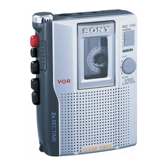
15/12/2014 TCM-200DV SECTION 2 GENERAL • Location of Controls BATT Built-in microphone REC TIME z REC x STOP SPEED CONTROL m REW/ REVIEW PAUSE . DC IN 3V Digitized in Heiloo, Holland... -
Page 4: Disassembly
15/12/2014 TCM-200DV SECTION 3 DISASSEMBLY Note: Follow the disassembly procedure in the numerical order given. SPEAKER (SP901), CASSETTE LID ASSY MECHANISM DECK REAR CABINET MAIN BOARD (MT-200DV-175) 3-1. Speaker (SP901), Cassette Lid Assy 2 boss qa cassette lid assy q;... -
Page 5: Rear Cabinet
15/12/2014 TCM-200DV 3-2. Rear Cabinet two claws claw 6 rear cabinet 4 two screws (BTP 1.7 × 9 ) claw two claws 3 screw (BTP 1.7 × 9 ) 2 screw (1.7 × 16 ) 3-3. MAIN Board 5 three screws (M1.4) -
Page 6: Mechanism Deck (Mt-200Dv-175)
15/12/2014 TCM-200DV 3-4. Mechanism Deck (MT-200DV-175) 2 two screws (IB LOCK) 3 screw (SERRAT IB LOCK) 4 mechanism deck (MT-200DV-175) Digitized in Heiloo, Holland... -
Page 7: Mechanical Adjustments
15/12/2014 TCM-200DV SECTION 4 MECHANICAL ADJUSTMENTS 1. Clean the following parts with a denatured-alcohol-moistened swab: record/playback head pinch roller erase head rubber belt capstan idlers 2. Demagnetize the record/playback head with a head demagnetizer. (Do not bring the head demagnetizer close to the erase head.) 3. -
Page 8: Electrical Adjustments
15/12/2014 TCM-200DV SECTION 5 ELECTRICAL ADJUSTMENTS Tape Speed Adjustment Setting: • Supplied voltage: 2.5 V Mode: playback • Switch and control position [VOL control (RV101) : mechanical center test tape frequency [PAUSE switch (S301) : OFF WS-48A counter [SPEED CONTROL]... -
Page 9: Diagrams
15/12/2014 TCM-200DV SECTION 6 DIAGRAMS Note on Schematic Diagram Note on Printed Wiring Boards: • All capacitors are in µF unless otherwise noted. pF: µµF • X : parts extracted from the component side. 50 WV or less are not indicated except for electrolytics •... -
Page 10: Ic Block Diagrams
15/12/2014 TCM-200DV • IC Block Diagrams IC101 NJM2128M-TE2 IC102 LM4890MMX IC501 NJM2072 (TE2) SHUTDOWN PRE +IN PRE -IN BIAS INPUT BYPASS – PRE OUT OUTPUT2 S GND GAIN CONT POWER POWER POWER AMP A +IN A OUT A OUTPUT1 POWER –... -
Page 11: Block Diagram
15/12/2014 TCM-200DV 6-1. Block Diagram MIC901 IC102 J102 POWER AMP (PLUG IN POWER) – SP901 (SPEAKER) – IC101 (1/2) PRE AMP, RIPPLE FILTER RV101 BIAS SHUTDOWN HRP901 – (REC/PB) S101 (A) (PB/REC) HE901 (ERASE) S101 (F) (PB/REC) IC101 (2/2) -
Page 12: Printed Wiring Board - Main Board Side A
15/12/2014 TCM-200DV 6-2. Printed Wiring Board – MAIN Board Side A – MAIN BOARD (SIDE A) 1-686-273- (11) Digitized in Heiloo, Holland... -
Page 13: Printed Wiring Board - Main Board Side B
15/12/2014 TCM-200DV 6-3. Printed Wiring Board – MAIN Board Side B – MAIN BOARD (SIDE B) DRY BATTERY J101 SIZE"AA" (IEC DESIGNATION R6) DC IN 3V 2PCS. 3V S501 C124 IC102 J103 SP901 J102 IC101 (PLUG IN POWER) IC501... -
Page 14: Schematic Diagram
15/12/2014 TCM-200DV 6-4. Schematic Diagram R301 R302 TP13 C101 MIC901 R303 0.047 TP12 R305 R304 C105 1000p C302 R309 R311 R312 C117 C309 10 6.3V R316 4.7k 0.01 2.2M J102 R115 6.3V S101 R201 C104 C116 TP22 0.047 C107... -
Page 15: Exploded Views
15/12/2014 TCM-200DV SECTION 7 EXPLODED VIEWS NOTE: • Items marked “*” are not stocked since they • The mechanical parts with no reference num- • Abbreviation are seldom required for routine service. Some ber in the exploded views are not supplied. -
Page 16: Mechanism Deck Section-1 (Mt-200Dv-175)
15/12/2014 TCM-200DV 7-2. Mechanism Deck Section-1 (MT-200DV-175) HRP901 mechanism deck section-2 (MT-200DV-175) HE901 supplied M901 A (Included in No.151) Ref. No. Part No. Description Remarks Ref. No. Part No. Description Remarks 3-704-197-01 SCREW (M1.4), SPECIAL HEAD 3-703-816-24 SCREW (M1.4X2.5), SPECIAL HEAD 3-234-857-01 BELT (CAP) 3-703-925-21 SCREW (M1.4) -
Page 17: Mechanism Deck Section-2 (Mt-200Dv-175)
15/12/2014 TCM-200DV 7-3. Mechanism Deck Section-2 (MT-200DV-175) supplied B (Included in No.151) (Including A, B ) Ref. No. Part No. Description Remarks Ref. No. Part No. Description Remarks X-3381-206-1 CHASSIS ASSY (ARO) 3-229-064-01 WASHER, STOPPER 3-225-385-01 GEAR (B) 3-225-393-01 LEVER (SHUT/OFF) -
Page 18: Electrical Parts List
15/12/2014 TCM-200DV SECTION 8 MAIN ELECTRICAL PARTS LIST NOTE: • Due to standardization, replacements in the • Items marked “*” are not stocked since they • COILS uH: µH parts list may be different from the parts speci- are seldom required for routine service. - Page 19 15/12/2014 TCM-200DV MAIN Ref. No. Part No. Description Remarks Ref. No. Part No. Description Remarks R116 1-216-809-11 METAL CHIP 1/10W SW BOARD R117 1-216-805-11 METAL CHIP 1/10W ********* R120 1-216-825-11 METAL CHIP 2.2K 1/10W R121 1-216-825-11 METAL CHIP 2.2K 1/10W <...
- Page 20 15/12/2014 TCM-200DV REVISION HISTORY Clicking the version allows you to jump to the revised page. Also, clicking the version at the upper right on the revised page allows you to jump to the next revised page. Ver. Date Description of Revision 2002.09...