Table of Contents
Advertisement
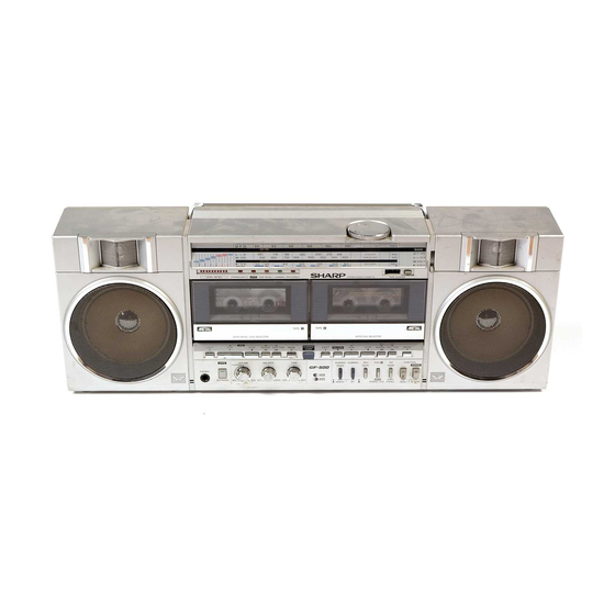
OUTSTANDING RECEPTION THE WORLD OVER
This Service Manual omits the descriptions about the adjustment
and block diagram of the Radio (High Frequency) Circuit, and for
their details, refer to the GF-54542 Service Manual (ATSM182013-
DIAL CORD STRINGING . . . . . . . . . . . . . . . . . . . . . . . . . . . . . . . . . . 2
NAMES OF CONTROLS . . . . . . . . . . . . . . . . . . . . . . . . . . . . . . . . . . . . . 3
CIRCUIT CONSTRUCTION . . . . . . . . . . . . . . . . . . . . . . . . . . . . . . . . . . . . 6
WIRING
SIDE
POWER SUPPLY SECTION OF GF-500 . . . . . . . . . . . . . . . . . . . . . . . . . . .
AC POWER SUPPLY CORD . . . . . . . . . . . . . . . . . . . . . . . . . . . . . . . . . . .
DECK 2 MECHANISM EXPLODED VIEW . . . . . . . . . . . . . . . . . . . . . . . . . . . .20
CABINET EXPLODED VIEW . . . . . . . . . . . . . . . . . . . . . . . . . . . . . . . .
REPLACEMENT PARTS LIST . . . . . . . . . . . . . . . . . . . . . . . . . . . . .
OF
PRINTED
WIRING
In the interests of user-safety the set should be
restored to its original condition and only parts
identical to those specified be used.
BOARD
2
2
. 9
18
19
Back
Advertisement
Table of Contents

Related Manuals for Sharp GF-500


Summary of Contents for Sharp GF-500
-
Page 1: Table Of Contents
SCHEMATIC DIAGRAM AND WIRING SIDE OF PRINTED WIRING BOARD AT POWER SUPPLY SECTION OF GF-500 ...... -
Page 2: Specifications
23 Transistors The GF-500Z Unit will operate on an AC power supply of The GF-500 Unit will operate on an AC power supply of 11 O- 120 Volts, or 220 - 240 Volts of 50Hz or 60Hz. For portable use it will operate on its internal batteries, or from an external portable use it will operate on its internal batteries, or from an 15 Volts DC supply (with an adaptor). -
Page 3: Names Of Controls
2. Power On/Battery Indicator 3. APPS Indicator 4. APPS End-Pause indicator 5. Dubbing Indicator 6. FM Stereo Indicator 7. Tuning Control 8. Fine Tuning Control 9. Deck 2: Digital Tape Counter 12. Built-in Microphone (Right Channel) 13. Deck 2: Cassette Compartment 14. -
Page 4: Disassembly
Caution: Prior to the disassembly, be sure to draw the AC power supply lead plug from the AC power supply socket of the unit and to unload the cassette compartment with a cassette tape and the battery compartment with batteries. Figure 4-2 Figure 4-1 Figure 4-3... -
Page 5: Audio Block Dlaikil
Figure 5 BLOCK DIAGRAM... -
Page 6: Circuit Construction
It is possible to select either normal tape speed or high tape speed when you perform dubbing from the deck 1 to the deck 2 and the high speed is twice as fast as the normal speed. Normal speed/high speed record selector circuit Deck 1 Deck 2 Being provided at the deck 2, the integrated circuit IC202... -
Page 7: Apps Flow Chart
APPS Flow Chart APPS not settable Deck 1 is in play mode? The motor stops and the yellow indicator lit at the time. with the dubbing switch turned off) The motor of Deck 1 gets in a stop: Deck 2 alone can be operated. - Page 8 position. (The indicators D302 and D314 are both put off). Deck 1 is in APSS mode or in stop mode. Deck 1 is in APSS mode? APPS set/clear switch is at “set” position. in stop. (The yellow indica- The motor of Deck 1 starts again. (The red indicator D302 is put off.) The motor of Deck 1 starts again.
-
Page 9: Mechanical Adjusim' Efi
P I N C H R O L L E R P R E S S U R E C H E C K 1. Place the unit in PLAY mode. 2. Push the pinch roller, at the point shown in Fig. 9-1, by using a tension gauge (500 gr.) so that it will come off the capstan. -
Page 10: Checking Of Audio (Low Frequency) Circuit
Oscilloscope Record Mode BIAS OSCILLATOR FREQUENCY CHECK 1. Make connection of instruments as shown in Fig. IO-l. 2. Set the function selector switch to “tape” and the beat cancel switch to “ A” . 3 . P l a c e t h e u n i t i n r e c o r d m o d e , a n d c h e c k t h a t t h e frequency counter reads 90 +5kHz. - Page 11 P l a y b a c k S i g n a l Line in Signal Record Signal Microphone Signal APSS Signal Phono Signal Figure 11...
- Page 12 S C H E M A T I C &RAM (l/Z)
- Page 13 F i g u r e I.3 W I R I N G S I D E O F F...
- Page 14 DE OF...
- Page 15 II I F i g u r e 1 5 S C H E M A T I C DlAGRAM (2/2)
- Page 16 F i g u r e 1 . 6 WIRING SIDE OF P.W. B O A R D (2/2)
-
Page 17: Schematic Diagram
SCHEMATIC DIAGRAM AND WIRING SIDE OF PRlNTED WlRlNG BOARD AT POWER SUPPLY SECTION OF GF-500... -
Page 18: Notes On Schematic Diagram
Ref. No. Names of Switch Switch Position SW1 (A - F) Band Selector Switch F M -SW1 -SW2 - A M Record/Playback Switch SW101 (A - J) Playback - Record Power Switch Function Selector Switch Tape/Line in - Radio FM Mode Selector Switch Mono - Stereo Tape Selector Switch O n - O f f... -
Page 19: Mechanism Exploded Vii
BOTTOM VIEW TOP VIEW Figure 19 DECK 1 MECHANISM E X P L O D E D V I E W... -
Page 20: Deck 2 Mechanism Exploded View
BOTTOM VIEW TOP VIEW F i g u r e 2 0 D E C K 2 M E C H A N I S M E X P L O D E D V I E W... -
Page 21: Cabinet Exploded View
Figure 21 CABINET EXPLODED VIEW... - Page 22 Figure 22 CABINET EXPLODED VIEW...
- Page 23 DESCRIPTION PART NO. CODE PART NO. DESCRIP CODE C 8 5 . 8 7 . 8 8 VCTYMFlCY223N O.O22MFD, 16V, -c30%, A A C316 Cl 07,108 RC-EZAI 07AFl A 1 OOMFD, 1 OV Cl 13,l 14 1 OOMFD, 16V 1 OOMFD, 1 OV Cl 15,l 16 1 OOOMFD, 16V C418...
- Page 24 RC-EZAI 06AFl C RC-EZAI 07AFl A FM IF FM Detector AM IF RC-EZAI 07AFl A 1 MFD, 50V 1 OOMFD, 16V (GF-500) Cl 19,120 Cl 23,124 COILS Cl 27,128 1 OOMFD, 1 OV Cl 31 ,I 32 Band Pass Filter...
- Page 25 To have your order filled promptly and correctly, please furnish the following information. 1. MODEL NUMBER 2. REF. NO. 3. PART NO. 4. DESCRIPTION _ _ _ _ NOTES: Parts marked with “ 6” are important for malntalning the safety of the set. Be sure to replace these parts ,flrth specified ones for malntainlng the safety and performance of the set.
- Page 26 PART NO. DESCRIPTION CODE DESCRIPTION CODE PART NO. C423 RESISTORS 100 ohm s y m b o l MF o f t h e p a r t N o . VRD-MFOOOOOOO: t h i s M F d o e s n o t 220 ohm m e a n l e a d wre.
- Page 27 MISCELLANEOUS Compartment Rod, Record/Playback Front Cabinet Assembly BD Selector Lever Spring, Battery Terminal Spring, Batten/ Terminal Spring, Cassette Rear Cabinet (GF-500) AX Compartment Lock Lever Rear Cabinet (GF-500Z) AX Spring, Cassette Compartment Guide (Right) Assembly Spring, Cassette GFTAC121 BAFSA Cassette Compartment...
- Page 28 PART NO. DESCRIPTION PART NO. CODE CODE Lever, Operation Block. Assembly Plate. Deck 1 Operation A8 Lever Blocking Plate, Deck 2 Operation AB Turntable LRTNP0051 AFZZ Retaining Ring, Sensor Lever Blocking Lever Lever, One-touch Interlocking Lever, Main Switch Interlocking Lever, Main Switch Retaining Lever, Playback Lever, Deck 2 Record...
- Page 29 CODE DESCRIPTION PART NO. DESCRIPTION PART NO. CODE Fuse, T1.25A (GF-500Z) Fuse, 1.5A (GF-500) Socket, Line/Phone Input 820 ohm Earth Terminal Sockets, Line Output 39K ohm Sockets, External Microphone 270 ohm Sockets, External Speaker AE 33K ohm QJAKJOI OGAFZZ Sockets, Headphones R403.404.
-
Page 30: Sharp Corporation
430 E. Plainfield Rd. Countryside, Illinois U.S. Subsidiary of Sharp Corporation, Osaka, Japan Parts Centers: 07652 P.O. Box 664 Paramus, New Jersey Long Beach, 90810 637-9488 60525 La Grange, Illinois 482-9292 Writer and Editor: Engineering Administration of Audio Systems Group, Sharp Corp.