Table of Contents
Advertisement
Counter module FM 450-1
SIMATIC
S7-400
Counter module FM 450-1
Manual
02/2014
A5E03648739-02
___________________
Preface
___________________
Product Overview
This is how the FM 450-1
___________________
counts
___________________
Installation and Removal
___________________
Wiring
___________________
Parameter assignment
___________________
Program
___________________
Commissioning
___________________
Modes, settings, parameters
and commands
Encoder signals and their
___________________
evaluation
___________________
Assignment of the DB
___________________
Errors and diagnostics
___________________
Technical Data
___________________
Spare parts
___________________
References
1
2
3
4
5
6
7
8
9
10
11
12
13
14
Advertisement
Table of Contents

Related Manuals for Siemens simatic s7-400 FM 450-1


Summary of Contents for Siemens simatic s7-400 FM 450-1
- Page 1 ___________________ Counter module FM 450-1 Preface ___________________ Product Overview This is how the FM 450-1 ___________________ counts SIMATIC ___________________ Installation and Removal S7-400 ___________________ Counter module FM 450-1 Wiring ___________________ Parameter assignment Manual ___________________ Program ___________________ Commissioning ___________________ Modes, settings, parameters and commands Encoder signals and their ___________________...
- Page 2 Note the following: WARNING Siemens products may only be used for the applications described in the catalog and in the relevant technical documentation. If products and components from other manufacturers are used, these must be recommended or approved by Siemens. Proper transport, storage, installation, assembly, commissioning, operation and maintenance are required to ensure that the products operate safely and without any problems.
-
Page 3: Preface
Additional support If you have any further questions about the use of products described in this manual and do not find the right answers here, contact your local Siemens representative (http://www.siemens.com/automation/partner): A guide to the technical documentation for the various products and systems is available on the Internet: ●... - Page 4 Technical Support You can access technical support for all A&D projects via the following: ● Online support request form: (http://www.siemens.com/automation/support-request) Service & Support on the Internet In addition to our documentation, we offer a comprehensive online knowledge base on the...
-
Page 5: Table Of Contents
Table of contents Preface ..............................3 Product Overview ............................ 9 Chapter overview ........................... 9 Properties ............................. 10 Fields of applications of the FM 450-1 ..................12 The FM 450-1 hardware ......................13 The FM 450-1 software ........................ 16 This is how the FM 450-1 counts ......................19 Basics ............................ - Page 6 Table of contents Commissioning ............................. 55 Chapter overview ........................55 Working steps during mechanical installation ................56 Working steps for parameter assignment ................... 59 Modes, settings, parameters and commands ..................65 Chapter overview ........................65 Overview of modes, settings and commands ................66 Basics on calling modes, settings and commands ..............
- Page 7 Table of contents Spare parts ............................119 References ............................121 Glossary ............................. 123 Index..............................127 Counter module FM 450-1 Manual, 02/2014, A5E03648739-02...
- Page 8 Table of contents Counter module FM 450-1 Manual, 02/2014, A5E03648739-02...
-
Page 9: Product Overview
Product Overview Chapter overview Section overview This section provides you with an overview of the FM 450-1 function module. ● It informs you of what the FM 450-1 can do. ● Examples demonstrate some of the possible applications of the FM 450-1. ●... -
Page 10: Properties
Product Overview 1.5 The FM 450-1 software Properties Properties The FM 450-1 is a fast counter module to be used in the S7-400 automation system. There are two counters on the module which can work in the following counting ranges as required: ●... - Page 11 Product Overview 1.5 The FM 450-1 software Diagnostic interrupt When the following events occur, the FM 450-1 can trigger a diagnostic interrupt: ● External auxiliary voltage faulty ● Encoder 5.2 VDC supply faulty ● Module not assigned parameters or errors in parameter assignment ●...
-
Page 12: Fields Of Applications Of The Fm 450-1
Product Overview 1.5 The FM 450-1 software Fields of applications of the FM 450-1 You can use the FM 450-1 as follows: The main field of application of the FM 450-1 is where it is necessary to count signals with high frequencies and fast reactions must be triggered when a prescribed counter reading is reached. -
Page 13: The Fm 450-1 Hardware
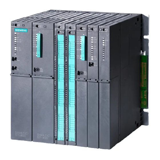
Product Overview 1.5 The FM 450-1 software The FM 450-1 hardware View of module The illustration shows the FM 450-1 module with front connector plugged in. Figure 1-2 Illustration of the FM 450-1 Order number and version The full order number of the FM 450-1 is shown on the rating plate. The abbreviated order number and the version of the FM 450-1 are marked on the top end of the front of the module. - Page 14 Product Overview 1.5 The FM 450-1 software Diagnostic and status LEDs The FM 450-1 has 16 LEDs. The LEDs are for diagnostic purposes and indicate the state of the FM 450-1 and its digital inputs and outputs. The following table lists labeling, color and function of the LED displays.
- Page 15 Product Overview 1.5 The FM 450-1 software Front connector coding If you hook in the front connector, the front connector coding engages. Thereafter this front connector can only be attached to an FM 450-1 module. Labeling strips A plate block with four labeling strips is included with the module. These strips can be labeled individually with the corresponding signal names.
-
Page 16: The Fm 450-1 Software
Product Overview 1.5 The FM 450-1 software The FM 450-1 software Software packages of the FM 450-1 You will require the software package on the supplied CD to integrate the FM 450-1 into the S7-400. It includes: ● Parameterization software with parameterization interfaces ●... - Page 17 Product Overview 1.5 The FM 450-1 software Software for the S7-400-CPU The software for the CPU consists of the FC CNT_CTRL function, which is invoked in the CPU user program. This FC enables communication between the CPU and the FM 450-1. In addition, there is also the FC DIAG_INF for the FM 450-1 with which you can transmit diagnostic data into the DB of FC CNT_CTRL.
- Page 18 Product Overview 1.5 The FM 450-1 software Counter module FM 450-1 Manual, 02/2014, A5E03648739-02...
-
Page 19: This Is How The Fm 450-1 Counts
This is how the FM 450-1 counts Basics What is counting? Counting refers to the recording and totaling of events. In the case of the FM 450-1 function module encoder signals are captured and evaluated accordingly. Count range, count limits The FM 450-1 can count both forwards and backwards. - Page 20 This is how the FM 450-1 counts 2.2 Gate functions Continuous counting If when counting in the up direction a counter has reached the high count limit and a further count pulse comes, then the counter jumps to the low count limit and begins to total the count pulses;...
- Page 21 This is how the FM 450-1 counts 2.1 Basics Periodic counting For periodic counting the respective counter starts from the load value. If when counting up the counter reaches the high count limit and further count pulses come, then the counter jumps to the load value and starts totalizing the count pulses.
-
Page 22: Gate Functions
This is how the FM 450-1 counts 2.2 Gate functions Gate functions Counting with gate functions Many applications require that the counting process should be started or stopped at a specifically defined point in time, depending on other events. In the case of the FM 450-1 starting and stopping the counting process like this take place via a gate function. -
Page 23: Installation And Removal
Installation and Removal Chapter overview Overview In this chapter you will find information on the installation and removal of the FM 450-1 ● You will find out what you have to pay attention to during installation. You will obtain information on project planning and on the design of an FM 450-1 ●... -
Page 24: Preparing For Mounting
Installation and Removal 3.4 Removal of the FM 450-1 Preparing for Mounting Important safety rules There are important rules to be observed when integrating an S7-400 with an FM 450-1 into a plant or a system. These rules and regulations are explained in manual /1/. Defining the slots The FM 450-1 function module can be installed like a signal module in any central device or extension device. -
Page 25: Installing The Fm 450-1
Installation and Removal 3.3 Installing the FM 450-1 Installing the FM 450-1 Rules No special protective measures (EGB guidelines) are required for installing the FM 450-1. Tools required You require a 4.5 mm screwdriver to install the FM 450-1. Installation procedure Proceed as follows to install an FM 450-1 1. -
Page 26: Removal Of The Fm 450-1
Installation and Removal 3.4 Removal of the FM 450-1 Removal of the FM 450-1 Rules No special protective measures (EGB guidelines) are required for removing the FM 450-1. Tools required You require a 4.5 mm screwdriver to remove the FM 450-1. Procedure for removal Proceed as follows to remove an FM 450-1 1. -
Page 27: Wiring
Wiring Chapter overview Chapter overview In this chapter you will find information on wiring the FM 450-1 ● Terminal assignment of the front connector. ● Terminal functions. ● Notes on the selection of cables. ● Procedure when wiring the front connector. ●... -
Page 28: Terminal Assignment Of The Front Connector
Wiring 4.4 Module status after power is switched on Terminal assignment of the front connector Front connectors You connect the following to the 48-pin front connector: ● count signals, ● digital inputs ● digital outputs ● encoder power supply ● auxiliary voltage and load voltage. The following illustration shows the front side of the front connector, the strip with the terminal assignment printed on and the labeling strips. - Page 29 Wiring 4.4 Module status after power is switched on Figure 4-1 Front connector of the FM 450-1 Counter module FM 450-1 Manual, 02/2014, A5E03648739-02...
- Page 30 Wiring 4.4 Module status after power is switched on Assignment of front connector Table 4- 1 Assignment of front connector Terminal Name Inputs/ Function outputs 5 V encoder RS 24 V encoder, 24-V pulse 24 V initiator 422, symmetrical asymmetric encoder with direction level 24 V auxiliary voltage supply for encoders...
- Page 31 Wiring 4.4 Module status after power is switched on Terminal Name Inputs/ Function outputs 5 V encoder RS 24 V encoder, 24-V pulse 24 V initiator 422, symmetrical asymmetric encoder with direction level Counter 1 Digital input 1I0 Digital input 1I1 Digital input 1I2 (set counter) Digital output 1Q0 Digital output 1Q1...
- Page 32 Wiring 4.4 Module status after power is switched on 5.2 VDC encoder power supply The module generates a 5.2 VDC voltage from the 1L+/1M auxiliary voltage at a maximum current of 300mA per count channel; this voltage is available on the respective "DC5.2V" terminal to supply a 5 V encoder with short circuit-proof voltage.
- Page 33 Wiring 4.4 Module status after power is switched on Input filter for 24 V encoder signals To suppress faults you can assign parameters to the input filters (RC elements) with a uniform filtering time for the 24 V inputs A*, B* and N*. The following two input filters are available for each counter: Table 4- 2 Input filter for 24 V encoder signals...
- Page 34 Wiring 4.4 Module status after power is switched on Digital outputs For the purpose of directly initiating control processes, the FM 450-1 has the digital outputs 1Q0 and 1Q1 (for counter 1) or 2Q0 and 2Q1 (for counter 2) that are supplied via the load voltage 2L+.
-
Page 35: Wiring Front Connectors
Wiring 4.4 Module status after power is switched on Wiring Front Connectors Cables There are a few rules you must observe when selecting the cables: ● The cables for the digital inputs must be shielded. ● The cables for the count signals must be shielded. ●... - Page 36 Wiring 4.4 Module status after power is switched on Figure 4-2 Connecting incremental 5 V encoders Terminal 4 (1M) of the front connector must be connected with the ground of the CPU with a low impedance. If you supply the encoder with external voltage, you must also connect the ground of this external voltage supply to the ground of the CPU.
- Page 37 Wiring 4.4 Module status after power is switched on Figure 4-3 Incremental 24 V encoder connection ● Use flexible cables with cross sections of 0.25 to 1.5 mm Note If the encoder is supplied via the module, the cable cross section must be selected large enough for sufficient voltage to be applied to the encoder via the cable in spite of a drop in voltage.
- Page 38 Wiring 4.4 Module status after power is switched on Wiring steps Proceed as follows when wiring the front connector: WARNING Injury to persons can occur. If you wire the FM 450-1 front connector when the power is switched on, you may injure yourself owing to an electric shock.
-
Page 39: Module Status After Power Is Switched On
Wiring 4.4 Module status after power is switched on Module status after power is switched on Characteristics After the power supply has been switched on and before any data have been transmitted, the module status is as follows: ● Counter inputs with default setting for 5 V differential signals, track B not inverted; single evaluation (refer to the section "Signal evaluation (Page 100)") ●... - Page 40 Wiring 4.4 Module status after power is switched on Counter module FM 450-1 Manual, 02/2014, A5E03648739-02...
-
Page 41: Parameter Assignment
Parameter assignment Chapter overview Chapter overview In this chapter you will learn how to install and start parameter assignment screen forms. The parameter assignment screen forms have an integrated help function to support you with parameter assignment and commissioning of the FM 450-1. Counter module FM 450-1 Manual, 02/2014, A5E03648739-02... -
Page 42: Installing And Calling Parameter Assignment Screen Forms
Important information can be found in the readme file. Result The components of the configuration package are installed in the following directories: ● SIEMENS\STEP7\S7LIBS\FMx501LIB:FCs, UDTs ● SIEMENS\STEP7\S7FCOUNT: Configuration software, Readme, Online Help ● SIEMENS\STEP7\EXAMPLES: Examples ● SIEMENS\STEP7\S7MANUAL\S7FCOUNT: Getting Started, Manuals Installing parameter assignment screen forms Call the SETUP.EXE program on the backup copy of your installation diskette. - Page 43 Parameter assignment 5.2 Installing and calling parameter assignment screen forms Reading the readme file Important up-to-date information about the provided software can be found in a readme file. You can read this file with the WORDPAD editor in Windows. Calling parameter assignment screen forms The parameter assignment screen forms are displayed automatically after successful installation, if you assign the FM 450-1 parameters within the hardware configuration Calling the integrated help...
- Page 44 Parameter assignment 5.2 Installing and calling parameter assignment screen forms Counter module FM 450-1 Manual, 02/2014, A5E03648739-02...
-
Page 45: Program
Program Chapter overview Chapter overview In this chapter you can find all the information you require to program the FM 450-1 in the S7-400. Two STEP 7 blocks are provided for integrating the FM 450-1 into a user program and make handling the desired functions as easy as possible for you. This chapter describes these blocks. -
Page 46: The Fc Cnt_Ctrl Function
Program 6.5 Technical specifications of the blocks The FC CNT_CTRL function Functionality The data required for the FC CNT_CTRL are stored in a DB on the CPU. The FC CNT_CTRL transfers data cyclically from this DB to the FM and fetches data from the Requirement ●... - Page 47 Program 6.5 Technical specifications of the blocks Example The following contains an example of how you can implement the transfer of the module address, the channel address, and the length of the user data to the DB in OB 100. The symbol table contains the following assignments for this example: FM450_DB_K1 DB 10...
- Page 48 Program 6.5 Technical specifications of the blocks Call The FC CNT_CTRL can be called once per counter either cyclically or in a time-controlled program. Calling in the interrupt program is not permissible. Calling the FC CNT_CTRL in the STL and LAD representations is rendered below. Figure 6-1 Calling the FC CNt_CTRL Parameters of the FC CNT_CTRL...
- Page 49 Program 6.5 Technical specifications of the blocks Name Declaration type Data type Meaning The user... The block... RES_SYNC IN-OUT BOOL Delete "synchronization" sets queries and status bit resets this RES_ZERO IN-OUT BOOL Reset status bits for zero sets queries and crossing, overflow, resets this underflow and comparator or...
-
Page 50: The Fc Diag_Inf Function
Program 6.5 Technical specifications of the blocks The FC DIAG_INF function Functionality The FC DIAG_INF reads data record DS1 from the FM 450-1 and makes it available to you in the DB of the FC CNT_CTRL. Transfer proceeds as follows: ●... -
Page 51: Example Application
Program 6.5 Technical specifications of the blocks Example application Example for the use of the FC CNT_CTRL The following example is representative for all functions and demonstrates the "Transfer load value to FM 450-1" and "Start counter" functions to show how the FC°CNT_CTRL can be applied. - Page 52 Program 6.5 Technical specifications of the blocks Description of the symbols The tables lists the symbols used in the example. You specify your own symbol assignments in the S7 symbol table. Table 6- 1 Symbols in the user program Symbols used Absolute (example) Comment CHANNEL1...
-
Page 53: Technical Specifications Of The Blocks
Program 6.5 Technical specifications of the blocks Technical specifications of the blocks Table 6- 2 Technical Specifications FC CNT_CTRL FC DIAG_INF Block number FC 0 FC 1 Version Assignment in work memory 540 bytes 246 bytes Assignment in load memory 634 bytes 326 bytes Assignment in local data area... - Page 54 Program 6.5 Technical specifications of the blocks Counter module FM 450-1 Manual, 02/2014, A5E03648739-02...
-
Page 55: Commissioning
Commissioning Chapter overview Chapter overview In this chapter you will find checklists for commissioning the FM 450-1. These checklists enable you to ● check all working steps up to full operation of the module, ● avoid operating faults by the module. Counter module FM 450-1 Manual, 02/2014, A5E03648739-02... -
Page 56: Working Steps During Mechanical Installation
Commissioning 7.3 Working steps for parameter assignment Working steps during mechanical installation Check list Use the following checklist to check and document the working steps during mechanical installation of the FM 450-1. Working step Options/procedure Define the slot All slots that are not already occupied or due to be occupied by a power supply module, a CPU or an IM. - Page 57 Commissioning 7.3 Working steps for parameter assignment Working step Options/procedure Connect 24 V encoders Counter 1: Terminal Name Function 24V incremental encoders Ground for encoder power supply 24 VDC 24 V encoder power supply Encoder signal A* Encoder signal B* Encoder signal N* Counter 2: Terminal...
- Page 58 Commissioning 7.3 Working steps for parameter assignment Working step Options/procedure Wiring digital inputs and Counter 1: Terminal Name Function outputs Digital inputs and outputs Digital input START Digital input STOP Digital input SET Digital output Q0 Digital output Q1 Counter 2: Terminal Name Function...
-
Page 59: Working Steps For Parameter Assignment
Commissioning 7.3 Working steps for parameter assignment Working steps for parameter assignment Check list Use the following checklist to check and document the working steps during parameter assignment of the FM°450-1. Assign the parameters of the FM°450-1 counters in the same order as the check list. - Page 60 Commissioning 7.3 Working steps for parameter assignment Step Options/procedure Assign the FM 450-1 Select encoders for counter 2 parameters 5-V encoder with Monitoring A + B + N symmetrical signals A + B None 24-V encoder with Interface Current-sinking output asymmetrical signals Current-sourcing output/push-pull...
- Page 61 Commissioning 7.3 Working steps for parameter assignment Step Options/procedure Assign the FM 450-1 Specify mode for counter 2 parameters Continuous counting Without gate With SW gate With HW gate Single counting With SW gate With HW gate Periodic counting With SW gate With HW gate Set count range 0 to +32 bit...
- Page 62 Commissioning 7.3 Working steps for parameter assignment Step Options/procedure Assign the FM 450-1 Specify the behavior of the digital outputs for counter 1 parameters Output 1Q0 Disable Active from comparison value 1 to overflow Active from comparison value 1 to underflow Active for "pulse duration"...
- Page 63 Commissioning 7.3 Working steps for parameter assignment Step Options/procedure Assign the FM 450-1 Enable digital outputs parameters CTRL_DQ0 in DB 1 CTRL_DQ1 in DB 1 Specify load value and comparison values for counter 1 and enter in DB Load value Comparison value 1 Comparison value 2 Specify load value and comparison values for counter 2 and enter in DB...
- Page 64 Commissioning 7.3 Working steps for parameter assignment Counter module FM 450-1 Manual, 02/2014, A5E03648739-02...
-
Page 65: Modes, Settings, Parameters And Commands
Modes, settings, parameters and commands Chapter overview Chapter overview This chapter gives you ● an overview of the three modes, the various settings and the commands available and how to call them. ● A description of the three modes ● A description of the settings ●... -
Page 66: Overview Of Modes, Settings And Commands
Modes, settings, parameters and commands 8.12 Initiating a process interrupt Overview of modes, settings and commands Which modes are available? For the FM°450-1 there are the three following modes: Table 8- 1 Operating modes of FM°450-1 Name Description Continuous counting Starting from the current counter status the FM°450-1 counts (with or without gate) continuously. - Page 67 Modes, settings, parameters and commands 8.12 Initiating a process interrupt Which commands are available? You can influence the counting process of the FM 450-1 by means of the following commands: Table 8- 3 The FM 450-1 commands Name Description Open and close gate The counting process starts when a gate opens and ends when it closes.
-
Page 68: Basics On Calling Modes, Settings And Commands
Modes, settings, parameters and commands 8.12 Initiating a process interrupt Basics on calling modes, settings and commands Calling modes, settings and commands ● You select modes and settings in the FM°450-1 parameter assignment screen forms. The parameter assignment data are automatically stored on the programming device and in the rack SDB. -
Page 69: Infinite Counting
Modes, settings, parameters and commands 8.12 Initiating a process interrupt Infinite counting Overview In this mode an FM 450-1 counter counts infinitely from the current counter status: ● When counting up, if the counter reaches the upper count limit and a further count pulse comes, it jumps to the lower limit and continues counting from there without any pulse loss. - Page 70 Modes, settings, parameters and commands 8.12 Initiating a process interrupt Opening and closing HW gate You open and close the HW gate of the relevant counter by applying or removing the corresponding signals to or from the inputs 1I0 and 1I1 (counter 1) and/or 2I0 and 2I1 (counter 2).
-
Page 71: Single Counting
Modes, settings, parameters and commands 8.12 Initiating a process interrupt Single counting Overview In this mode an FM°450-1 counter counts once from the load value up to the count limit. Select gate function In this mode you can select the gate function Options: ●... - Page 72 Modes, settings, parameters and commands 8.12 Initiating a process interrupt Opening and closing HW gate You open and close the hardware gate and set the counter to the load value by applying or removing the relevant signals at the inputs 1I0 and 1I1 (Counter 1) and/or 2I0 and 2I1 (Counter 2).
-
Page 73: Periodic Counting
Modes, settings, parameters and commands 8.12 Initiating a process interrupt Periodic counting Overview In this mode an FM 450-1 counter counts once from the load value up to the count limit, jumps back to the load value and continues to count. Select gate function In this mode you can select the gate function Options: ●... - Page 74 Modes, settings, parameters and commands 8.12 Initiating a process interrupt Opening and closing HW gate You open and close the HW gate and set the counter to the load value by applying or removing the relevant signals at the inputs 1I0 and 1I1 (counter 1) and/or 2I0 and 2I1 (counter°2).
-
Page 75: Count Range
Modes, settings, parameters and commands 8.12 Initiating a process interrupt Count range Introduction There is a 32°bit-wide count register on the module. With the count range you specify if the module counts only in the positive range or if the 32nd°bit is interpreted as a sign bit and hence negative numbers can be represented. -
Page 76: Setting: Behavior Of The Digital Outputs
Modes, settings, parameters and commands 8.12 Initiating a process interrupt Setting: Behavior of the digital outputs Introduction You can store two comparison values (comparison value 1 and 2) for the counters on the module; these are assigned to the respective digital outputs (comparison value°1: 1Q0 and 2Q0, comparison value 2: 1Q1 and 2Q1). - Page 77 Modes, settings, parameters and commands 8.12 Initiating a process interrupt Behavior of the outputs For the two outputs you can set one of six possible responses to reaching the comparison value. The various options are shown in the following table. Digital output parameter Behavior of the outputs assignment...
- Page 78 Modes, settings, parameters and commands 8.12 Initiating a process interrupt Boundary conditions If you assign the behavior of the digital outputs, you must observe the following boundary conditions. If ... then..you want to assign parameters for the output to ...you must ensure that the time between the be "active between the comparison value and the events is longer than the minimum operating time...
-
Page 79: Setting: Pulse Duration
Modes, settings, parameters and commands 8.12 Initiating a process interrupt Setting: Pulse duration Introduction As a means of adaptation to the actors used in your process (contactors, control elements etc.) you have the possibility of specifying a pulse duration during which the outputs are set when a comparison value is reached. -
Page 80: Command: Open And Close Gate
Modes, settings, parameters and commands 8.12 Initiating a process interrupt 8.10 Command: Open and close gate Overview The FM 450-1 counters have the following gates: ● A hardware gate (HW gate) which you can open and close level controlled or edge controlled. - Page 81 Modes, settings, parameters and commands 8.12 Initiating a process interrupt Edge controlled opening and closing of the HW gate The following figure shows the edge controlled opening and closing of the HW gate of counter 1. Figure 8-5 Edge controlled opening and closing of the HW gate of counter 1 With the edge controlled door function the HW gate of counter 1 is opened by a positive edge on input 1I0.
- Page 82 Modes, settings, parameters and commands 8.12 Initiating a process interrupt Opening and closing the SW gate The following figure shows the opening and closing of the SW gate of counter 1. Figure 8-6 Opening and closing the SW gate The SW gate is opened and closed by setting and resetting the input parameter SW_GATE of the FC CNT_CTRL.
-
Page 83: Command: Set Counter
Modes, settings, parameters and commands 8.12 Initiating a process interrupt 8.11 Command: Set counter Overview If you want to start or continue the counting process of a counter from a specific value (the load value), you must assign parameters for the signal with which the counter is to be set to the load value. - Page 84 Modes, settings, parameters and commands 8.12 Initiating a process interrupt Setting the counter with an external signal The L_PREPAR input parameter prepares a new load value. You can choose between two different external signals with which you set a counter to the load value ●...
- Page 85 Modes, settings, parameters and commands 8.12 Initiating a process interrupt Setting counter with input 1I2 (2I2) A counter can be loaded with the load value via a rising edge at input 1I2 (2I2). You can specify the behavior of an FM°450-1 counter with a positive edge at input 1I2 (2I2) with the ENSET_UP and ENSET_DN variables in the DB of the FC_CNT_CTRL and by means of parameter assignment.
- Page 86 Modes, settings, parameters and commands 8.12 Initiating a process interrupt Setting counter once with input 1I2 (2I2) The following figure shows counter 1 being set once with input 1I2. The situation is analogous for counter 2 with input 2I2. In the case represented here, only ENSET_UP is set, i.e., the counter is set during up counting.
- Page 87 Modes, settings, parameters and commands 8.12 Initiating a process interrupt Multiple setting of the counter with input 1I2 (2I2) The following figure shows the multiple setting of counter 1with input 1I2. The situation is analogous for counter 2 with input 2I2. In the case represented here, only ENSET_UP is set, i.e., the counter is set during up counting.
- Page 88 Modes, settings, parameters and commands 8.12 Initiating a process interrupt Parameter assignment Behavior of the FM 450-1 counter Parameter assignment The counter is set only at the first rising edge of the zero mark. "single setting of counter" If the counter is to be set again, you must first set ENSET_UP or ENSET_DN again (edge evaluation).
- Page 89 Modes, settings, parameters and commands 8.12 Initiating a process interrupt Multiple setting with the zero mark The following figure shows multiple setting of counter 1 with the zero mark. In the case represented here, only ENSET_UP is set, i.e., the counter is set during up counting. The relevant counter is set with each first rising edge of the zero mark as long as ENSET_UP and input 1I2 are set.
-
Page 90: Initiating A Process Interrupt
Modes, settings, parameters and commands 8.12 Initiating a process interrupt 8.12 Initiating a process interrupt Introduction For the individual counters of the FM 450-1 you can set which events are to trigger a hardware interrupt during operation. For this purpose you parameterize the counter interrupts in the parameter assignment screen marks. - Page 91 Modes, settings, parameters and commands 8.12 Initiating a process interrupt Hardware interrupt OB, OB 4x If a hardware interrupt occurs, the user program is interrupted, the data are transferred from the module to the start information of the OB 4x and the OB 4x is called. The hardware interrupt is acknowledged by quitting the OB 4x.
- Page 92 Modes, settings, parameters and commands 8.12 Initiating a process interrupt Lost hardware interrupt If an event occurs that is to trigger a hardware interrupt and the same previous event has not yet been acknowledged, no further hardware interrupt is triggered; the hardware interrupt is lost.
-
Page 93: Encoder Signals And Their Evaluation
Encoder signals and their evaluation Chapter overview Chapter overview This chapter describes: ● which encoders you can connect to the counter module ● the time profile of the encoder signals ● the multiple evaluation of encoder signals by the counter module ●... -
Page 94: Encoders Which Can Be Connected
Encoder signals and their evaluation 9.5 Signal evaluation Encoders which can be connected Introduction The counter module can process rectangular count signals which were generated by incremental encoders or pulse generators. Incremental encoders scan a barcode to generate rectangular electrical pulses. They differ in terms of pulse amplitude and number of signals. -
Page 95: 5-V Differential Signals
Encoder signals and their evaluation 9.5 Signal evaluation 5-V differential signals Count signals of 5-V incremental encoders RS422 signals returned by the 5-V incremental encoder to the module: ● A and /A ● B and /B ● N and /N The signals /A, /B and /N are the inverted signals of A, B and N. - Page 96 Encoder signals and their evaluation 9.5 Signal evaluation Monitoring encoder signals The module monitors the cable connection, and detects wire-break or short-circuit. You can define which of the three signal pairs to include in monitoring in your program. There is no need to wire any unused signal pairs, if you have disabled the corresponding diagnostics functions in the program (monitoring.) An error state at all three signals indicates a defective encoder, or a short-circuit at the "5.2 V DC"...
-
Page 97: 24-V Signals
Encoder signals and their evaluation 9.5 Signal evaluation 24-V signals Count signals returned by 24-V encoders 24-V incremental encoders The 24-V incremental encoder returns the 24-V signals A*, B* and N* to the module. The A* and B* signals are phase-shifted by 90°. 24-V signals are marked with an asterisk "*"... - Page 98 Encoder signals and their evaluation 9.5 Signal evaluation 24-V pulse encoders without/with direction signal Encoders such as proximity switches (BERO) or light barriers return only a count signal which you wire to terminal A* of the front connector. in additional, you can wire a signal for direction detection to terminal B* of the relevant counter.
- Page 99 Encoder signals and their evaluation 9.5 Signal evaluation Input filters for the 24-V count inputs For the purpose of suppressing interference, you can parameterize input filters with a uniform filter time for the 24 V inputs A*, B* and N* and for the digital inputs. Input filters available: Table 9- 3 Input filters...
-
Page 100: Signal Evaluation
Encoder signals and their evaluation 9.5 Signal evaluation Signal evaluation Overview The counter module supports the count of signal edges. It usually evaluates the edge at A (A*) (single evaluation). Options in the program of increasing the resolution: ● Single evaluation ●... - Page 101 Encoder signals and their evaluation 9.5 Signal evaluation Double evaluation Double evaluation refers to the evaluation of the positive and negative edges of signal A. The logic level at signal B determines the count direction, i.e. the up or down count pulse. The diagram shows the double evaluation of signals: Figure 9-5 Double evaluation...
- Page 102 Encoder signals and their evaluation 9.5 Signal evaluation Counter module FM 450-1 Manual, 02/2014, A5E03648739-02...
-
Page 103: Assignment Of The Db
Assignment of the DB 10.1 Assignment of the DB DB for the FC°CNT_CTRL All data associated with a channel of the module are located in the DB of FC CNT_CTRL. The data structure and the length of the DB is determined by the variable declaration in FC CNT_CTRL. - Page 104 Assignment of the DB 10.1 Assignment of the DB Address Variable Data type Initial value Comment 27.2 A_BIT1_2 BOOL FALSE Reserved 27.3 A_BIT1_3 BOOL FALSE Reserved 27.4 A_BIT1_4 BOOL FALSE Reserved 27.5 A_BIT1_5 BOOL FALSE Reserved 27.6 A_BIT1_6 BOOL FALSE Reserved 27.7 A_BIT1_7...
- Page 105 Assignment of the DB 10.1 Assignment of the DB Address Variable Data type Initial value Comment 43.7 STS_SW_G BOOL FALSE Status SW gate (read user) 44.0 STS_SET BOOL FALSE Status digital input SET (read user) 44.1 STS_LATCH BOOL FALSE Reserved 44.2 STS_STA BOOL...
- Page 106 Assignment of the DB 10.1 Assignment of the DB Address Variable Data type Initial value Comment 57.3 RAM_FLT BOOL FALSE RAM fault 57.4 ADU_FLT BOOL FALSE ADC/DAC fault 57.5 FUSE_FLT BOOL FALSE Fuse 57.6 HW_INTR_FLT BOOL FALSE Hardware interrupt lost 57.7 RESERVED_3 BOOL...
-
Page 107: Errors And Diagnostics
Errors and diagnostics 11.1 Chapter overview Chapter overview Errors can occur owing to operator errrs or incorrect wiring which the module must communicate to the user. The errors and faults are divided into the following classes on the module: ● Faults displayed by the diagnostics LEDs that indicate internal and external module faults. -
Page 108: Faults Indicated Via The Diagnostics Leds
Errors and diagnostics 11.5 Operator error 11.2 Faults indicated via the diagnostics LEDs Where are the faults displayed? Faults are indicated by the two red diagnostics LEDs: ● The INTF diagnostics LED displays internal faults of the module. ● The EXTF diagnostics LEDdisplays external faults to the cable connections. Which fauts are displayed? The following faults are indicated by the two red diagnostics LEDs lighting up: Fault type/LED... -
Page 109: Initiation Of Diagnostics Interrupts
Errors and diagnostics 11.5 Operator error 11.3 Initiation of diagnostics interrupts What is a diagnostics interrupt? If the user program is to respond to an internal or external fault, you can set the parameters for a diagnostic interrupt that will break off the cyclical program of the CPU device and calls the diagnostics interrupt OB (OB 82). - Page 110 Errors and diagnostics 11.5 Operator error Diagnostic Data Records DS0 and DS1 The information as to which event triggered a diagnostic interrupt is stored in diagnostic data records DS0 and DS1. Diagnostics data record DS0 consists of 4 bytes; DS1 consists of 12 bytes, the first 4 bytes of which are identical to DS0.
- Page 111 Errors and diagnostics 11.5 Operator error Diagnostic data record DS1 Diagnostic data record DS 1 consists of 12 bytes. The first 4 bytes are identical to diagnostic data record DS0. The following table shows the assignment of the remaining bytes. All bits not listed have no meaning and are zero.
-
Page 112: Data Error
Errors and diagnostics 11.5 Operator error 11.4 Data error When do data errors occur? If new parameters are transferred to the module, the FM 450-1 checks these parameters. If errors occur during this check, the module reports these data errors. Wrong parameters are not accepted by the module. -
Page 113: Operator Error
Errors and diagnostics 11.5 Operator error 11.5 Operator error When do operator errors occur? Operator errors occur if you operate the module incorrectly by specifying the wrong control signals. Where are operator errors indicated? FC CNT_CTRL enters the operator error numbers in DB1. You can access this data word via the variable name "OT_ERR_B"... - Page 114 Errors and diagnostics 11.5 Operator error Counter module FM 450-1 Manual, 02/2014, A5E03648739-02...
-
Page 115: Technical Data
Technical Data 12.1 General technical specifications These general technical specifications are described in the manual /3/: ● Standards and certifications ● Electromagnetic compatibility ● Shipping and storage conditions ● Mechanical and climatic environment conditions ● Specifications for insulation tests, safety class, and degree of protection Design Guidelines SIMATIC products meet the requirements if you observe the design guidelines described in the manuals when installing and operating the equipment. -
Page 116: Technical Data
Technical Data 12.2 Technical Data 12.2 Technical Data Technical data Dimensions and Weight Dimensions WxHxD (mm) 25x290x210 Weight Approx. 650 g Voltages, currents, potentials Auxiliary voltage 1L+/1M 24 VDC 20.4 ... 28.8 V Range, static • 18.5 ... 30.2 V Range, dynamic •... - Page 117 Technical Data 12.2 Technical Data Status, interrupts, diagnostics Status display Yes, 14 green LEDs for status of CR, DIR, inputs and outputs Interrupts Yes, configurable Hardware interrupt • Yes, configurable Diagnostic interrupt • Diagnostics functions Yes, 2 red LEDs Fault indication for internal and external faults •...
- Page 118 Technical Data 12.2 Technical Data Data to the count signals and the digital inputs and outputs (applies to both counters) Digital outputs 2L+ / 2M Supply voltage • Yes, toward all others except the digital inputs Electrical isolation • Output voltage •...
-
Page 119: Spare Parts
Spare parts Spare parts The table lists all the spare parts for the FM 450-1 you can order for this module either additionally or at a later date. Table 13- 1 Accessories and spare parts Parts for the FM 450-1 Order number Labeling sheet for the front connector, petrol blue 6ES7492-2AX00-0AA0... - Page 120 Spare parts Counter module FM 450-1 Manual, 02/2014, A5E03648739-02...
-
Page 121: References
The table below lists all manuals to which reference is made in the present manual. Title Order number SIMATIC; S7-400 Automation System; Installation Part of package (http://support.automation.siemens.com/WW/view/en/1117849) 6ES7498-8AA04-8AA0 SIMATIC; System software for the S7-300/400 system and Part of package standard functions 6ES7810-4CA07-8AW1 (http://support.automation.siemens.com/WW/view/en/44240604) - Page 122 References Counter module FM 450-1 Manual, 02/2014, A5E03648739-02...
-
Page 123: Glossary
Glossary Asymmetrical signals Refers to two pulse sequences, phase-shifted by 90°, and with zero mark signal where applicable. Configuration Assignment of modules to racks, slots and addresses. Users configuring the hardware fill out a configuration table in STEP 7. Double evaluation In this mode, the module evaluates all positive edges of the pulses at track A and B of an incremental encoder. - Page 124 Glossary Incremental encoder Incremental encoders are used to record distance, position, velocity, speed or weight units by counting small increments. Increments per encoder revolution Defines the number of increments the encoder outputs per revolution. The "output disable" (OD) signal is used in STOP and HOLD state to force all modules of an S7 automation system to safe state.
- Page 125 Glossary Sinking output Encoder output which returns an active low signal to 0 V (ground) Sourcing output Sourcing output of the encoder which returns an active high signal +24 V. STOP STOP as an international term, for example, as an operating command. STOPP STOPP (German spelling) as a term used in the manual to define an action which is not a command.
- Page 126 Glossary Counter module FM 450-1 Manual, 02/2014, A5E03648739-02...
-
Page 127: Index
Index 0 to +32 bit counting range, 75 Data error, 112 Diagnostic data record DS0 Assignment, 110 Diagnostic data record DS1 Assignment, 111 24 V encoder signals, 32 Diagnostic interrupt, 109 Input filter, 33 Enabling, 109 24 VDC encoder power supply, 32 OB 82, 109 24-V encoder signals, 97 Diagnostics interrupt, 108... - Page 128 Index Terminal assignment, 28 Operator error, 113 Order number, 13 Gate stop function, 72, 74, 82 parameter assignment screen forms Integrated help function, 43 Parameter assignment screen forms Calling, 43 Hardware gate, 22 Installing, 42 Hardware interrupt, 10, 90 Periodic counting mode, 73 Enabling, 90 Pulse duration Initiating, 90...
- Page 129 Index STOP see digital inputs, 33 Supply of encoders, 31 SW gate Opening and closing the, 82 Status, 82 Symmetrical encoders, 95 VDC 5.2 encoder power supply, 32 Version, 13 View of module, 13 Zero crossing, 75 Counter module FM 450-1 Manual, 02/2014, A5E03648739-02...
- Page 130 Index Counter module FM 450-1 Manual, 02/2014, A5E03648739-02...