Table of Contents
Advertisement
Quick Links
Advertisement
Table of Contents

Related Manuals for ADEMCO Galaxy 16


Summary of Contents for ADEMCO Galaxy 16
- Page 1 16 and 16 plus Engineer’s Manual...
-
Page 3: Table Of Contents
Telecoms Connections (Galaxy 16 plus only) ........ 14 Connection to the PSTN ..............14 Connecting Additional Telecom Apparatus ..............15 The Galaxy 16 plus and BT RedCare STUs ..............15 Regulations ..................15 Public Switched Telephone Network (PSTN) Approval ......16 REN and SEN Numbers .............. - Page 4 Galaxy RS232 Module as a Serial Printer Interface ......23 Printer Interface Module ..............24 Galaxy Gold ..................25 Alarm Monitoring ................25 3GSTU-PLI (Galaxy 16 plus only) ........... 25 SECTION 3: GALAXY KEYPADS ........27 General ................... 27 Power Consumption ................27 Wiring ....................
- Page 5 Overview ..................37 Illegal Code Entries ....................... 37 Code Setting Attributes ....................37 The Galaxy 16/16 plus and Parts ........... 37 Setting the System (the A Key) ............38 Part Setting the System (The B Key) ..........39 Interrupted Setting (Full or Part) ............ 40 Setting with Omitted Zones ............
- Page 6 Table of contents (cont’d) SECTION 5: MENU OPTIONS ........45 General ................... 45 Engineer Mode ................. 45 Menu Access ................... 46 Direct Access ......................46 Menu Driven Access ....................47 Option 1 - Omit ................48 Engineer Function ................48 User Function ...................
- Page 7 Table of contents (cont’d) Option 7 – Zones ................67 Modifying Zones ................67 Zone Types ..................68 01 Final ......................... 68 02 Exit/Entry ......................... 68 03 Intruder ........................68 04 Keyswitch ....................... 68 05 Fire .......................... 69 06 Entry ........................69 07 Push Set ........................
- Page 8 Table of contents (cont’d) Option 9 – Log ................78 Viewing the Event Log from a Keypad ..........78 Printing the Event Log ............... 78 Event Log Details ................79 Option 10 – Time ................80 Summer Time ................... 80 Option 11 –...
- Page 9 13 Rprt Ent Alrm ................100 1 Never ........................100 2 Immediately ......................100 3 At Ent T/Out ......................100 Appendix A: System Modules and part numbers ......I Appendix B: Library (Galaxy 16 only) ..........III Appendix C: Event log messages ........... V...
-
Page 11: Introduction
The Galaxy 16 and 16 plus control panels are simple to install and program. Never- theless, please read the guide carefully before using the system and retain it for... -
Page 13: Quick Setup
Quick Setup Quick Setup To quickly set up a Galaxy 16 or 16 plus these simple steps should be followed. Note: these steps should not be followed for a first time set up procedure, only those familiar with the Galaxy 16 and 16 plus control panels should use the quick set up procedure. -
Page 15: Section 1: System Architecture
Galaxy 16 can be used to trigger a 3 GSTU (12 V). The Galaxy 16 plus has all the features of the Galaxy 16 (with the exception of the Line Fail zone) and also features an on-board dialler (telecom module) with Line Fail detection capabilities built in. - Page 16 8 7 6 5 4 3 2 1 AB and Power Ω x x x x x x x x Outputs resistor 16Ω 1 2 LF T HOLD Line Fail Tamper Programmable Outputs Bell Horn Output Strobe Hold - Offs Figure 1.1 Galaxy 16 PCB Layout.
- Page 17 Galaxy RS232 Module (optional) 4 Outputs (Programmable) Galaxy Smart Power Supply Unit (PSU) (addressed as 1) 8 Zones (Programmable) Either: Galaxy Remote Input/Output module (RIO) (Addressed as 1) 4 Outputs (Programmable) 8 Zones (Programmable) Figure 1.2 Galaxy 16 System Architecture.
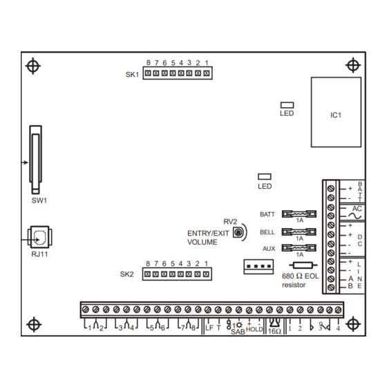
- Page 18 Ω Outputs resistor A B C D 16Ω 1 2 LF T HOLD Line Fail Tamper Programmable Outputs Bell Horn Output Hold - Offs Strobe Figure 1.3 Galaxy 16 plus PCB Layout...
- Page 19 Galaxy RS232 Module (optional) 4 Outputs (Programmable) Galaxy Smart Power Supply Unit (PSU) (addressed as 1) 8 Zones (Programmable) Either: Galaxy Remote Input/Output module (RIO) (Addressed as 1) 4 Outputs (Programmable) 8 Zones (Programmable) Figure 1.4 Galaxy 16 plus System Architecture.
-
Page 20: Stand-By Battery
Stand-by Battery The Galaxy 16/16 plus can accommodate a 15 Ahr stand-by battery in the control panel enclosure. Ensure that the battery connector leads on the control panel PCB are connected to the correct terminals on the battery. -
Page 21: Rs485 Data Communication Line (Ab Line)
AB line is 1 km. For more information see below. RS485 Wiring Recommendations GALAXY 16+ V2.7 GALAXY 16+ V2.7 Galaxy 16/16 plus Control Panel 08:58 TUE 22 NOV 08:58 TUE 22 NOV 680 Ω EOL R38 EOL Resistor (Factory fitted to... -
Page 22: Memory
Figure 1.8 P-Clip connection. Memory The Galaxy 16 and 16 plus control panels are fitted with a Non Volatile Memory (NVM) chip. This allows the panels to retain programming details when both the mains power and stand-by battery have been disconnected. The NVM can be transferred from a Galaxy 16 or 16 plus to another without loss of program- ming. -
Page 23: Zones
Zones Wiring Zones The zones on the Galaxy 16 and 16 plus control panels are end-of-line moni- tored. The zone is in the Closed condition when the system reads 1 kΩ and in the Open condition when the system reads 2 kΩ. The transition from 1 kΩ to 2 kΩ... -
Page 24: Wiring Multiple Zones
Keyswitch Wiring Wiring Multiple Zones Multiple detectors can be wired into a single zone as shown in Figure 1.10 Zone to Multiple Detector Wiring. It is recommended that the maximum number of detectors wired into a single zone is ten. (10 max) Alarm Alarm... -
Page 25: Wiring The Line Fail Zone
Wiring the Line Fail Zone The Galaxy 16 provides a dedicated Line Fail zone. This allows a digital commu- nicator, which can be attached to the Galaxy 16 outputs, to be monitored for communications failure. -
Page 26: Fixed Outputs
I t s i i t i Table 1.2 Galaxy 16/16 plus Outputs. Notes: SPCO Relay figures are ratings, all Transistor Voltage and current figures are output values. The output polarities (Positive removed) cannot be changed. -
Page 27: Voltage Outputs
Note: The Bell, Strobe and Hold-off outputs share a common fuse (F2). Programmable Outputs Outputs 1, 2 and 4 on the Galaxy 16 and 16 plus are negative applied (positive removed), transistorised outputs. The outputs can sink up to 400 mA and are used to drive output devices. -
Page 28: Telecoms Connections (Galaxy 16 Plus Only)
JP3) must be permanently connected (hard-wired) to the PSTN via a BT master socket, refer to Figure 1.14 Connecting the Galaxy 16 plus to the PSTN. Note: If the BT master socket is the newer type (NTE5), then the connection can be carried out by the installation engineer. -
Page 29: Connecting Additional Telecom Apparatus
A BT secondary socket, allowing additional telecom apparatus to be connected in series with the Galaxy 16 plus can be connected to the TNV port C and D (JP3) on the Galaxy 16 plus see Figure 1.14 Connecting the Galaxy 16 plus to the PSTN. -
Page 30: Public Switched Telephone Network (Pstn) Approval
• Operation with Call Process Monitor (CPM) tone recognition. • Multiple repeat attempts. Any other usage invalidates the approval of the Galaxy 16 plus if, as a result, it then ceases to comply with standards against which approval was granted. -
Page 31: Private Branch Exchange (Pbx) Connection
PBX Connection More than one item of series apparatus may be connected to the Galaxy 16 plus TNV ports marked C and D. This is limited by summing the Series Equivalence Number (SEN) shown on each item of series connected apparatus, ensuring that the sum of the SENs is not more than one (1). -
Page 33: Section 2: Optional Modules
RIO’s Section 2: OPTIONAL MODULES Galaxy Remote Input Output (RIO) Module A Galaxy RIO module can be connected to the Galaxy 16 and 16 plus to expand the system by eight zones and four outputs. – + – + LINE... -
Page 34: Rio Zones
RIO Zones The Galaxy RIO has eight programmable zones all of which default to Intruder. The wiring of the RIO zones is identical to that of the zones on the Galaxy 16 and 16 plus control panels, see Section 1: SYSTEM ARCHITECTURE; Zones RIO Outputs The RIO has four transistorised outputs, each output is positive removed. -
Page 35: Smart Power Supply Unit (Smart Psu)
RIO to overcome power problems that arise when the additional RIO is fitted distant to the control panel. Notes: Only one Smart PSU or one RIO can be connected to the Galaxy 16 and 16 plus control panels. -
Page 36: Rs232 Interface Module
Table 2.4 Smart PSU Output Default Functions. RS232 Interface Module The Galaxy RS232 module provides full duplex serial communication between the Galaxy 16/16 plus control panels and PCs or serial printers. This module has three main functions: • Copy and overwrite the control panel programming. -
Page 37: Rs232 Tamper
(overwritten) to one of the following: the same control panel, another Galaxy 16 or 16 plus, or to a PC with Galaxy Gold software installed; Galaxy Gold can then be used to modify the site program- ming. -
Page 38: Printer Interface Module
Printer Interface Module Table 2.6 RS232 Baud Rate Settings. Printer Interface Module The Printer Interface module allows the Galaxy to be connected to a serial printer and the contents of the event log and the programming details of the system to be printed. The module is available with either a: •... -
Page 39: Galaxy Gold
3GSTU-PLI The 3GSTU-PLI is a plug-on module which allows the Galaxy 16 plus to be connected to the BT RedCARE service. The 3GSTU-PLI connects to the SK1 and SK2 connector blocks on the Galaxy 16 plus PCB which supply the power, output and alarm input to the module. -
Page 41: Section 3: Galaxy Keypads
Section 3: GALAXY KEYPADS General The programming and operation of the Galaxy 16 and 16 plus control panels is carried out using the Galaxy Mark 7 (Mk V11) keypad. This keypad has a 2 × 16 character liquid crystal display. Up to three keypads can be fitted to the Galaxy 16/16 plus control panels. -
Page 42: Addressing
Table 3.2 Keypad Terminal Connections. Addressing The valid addresses for Galaxy keypads connected to a Galaxy 16/16 plus control panel are 0, 1, and 2. A 16-way rotary address switch is used to address Galaxy Mk III keypads. The address switch assigns a hexadecimal address value to the keypad. -
Page 43: Keypad Mounting Procedure
Keypad Installation aperture keyhole slot aperture cable channel cable stowage area sacrificial wall tamper elongated hole knockout hole 4-way connector Figure 3.2 Keypad Installation and Mounting Details. Keypad Mounting Procedure 1. Remove the keypad from its packaging. 2. To attach the keypad to the wall, the back plate must first be removed from the front plate. -
Page 44: Adding A Keypad To The System
2. Ensure that there are no more than two keypads already on the system 3. A new keypad can only be configured into a Galaxy 16 or 16 plus system from Engineer Mode. Configuring a Keypad on to the System To configure a keypad onto the system: 1. -
Page 45: Removing A Keypad From The System
The keypad is now configured into the system. Removing a Keypad from the System A keypad can only be removed from an existing Galaxy 16 and 16 plus system from Engineer Mode. 1. Access Engineer Mode from another keypad. -
Page 46: View Key
Keypad Operation Once access to the system has been gained, the number keys are also used to select and modify menu options allowing system programming and setting and unsetting of the system. View Key The A key is used to advance forwards through the menu „... -
Page 47: Star Key Features
12: Comms 1; 10 Access must be set up for Manager Authorise. Note: This option is available on the Galaxy 16 plus only. Ö Ö Ö Ö Ö 4: Toggles the keypad backlighting on/off. Ö Ö Ö Ö Ö 5: Activates a Medical alarm condition, see Section 5: MENU OPTIONS;... - Page 48 9 initiates the Engineer’s Test (Channel/Code 9) which sends a test signal to the Alarm Receiving Centre. Note: This option is available on the Galaxy 16 plus only. Ö Ö Ö Ö Ö ent: Entering the Manager Code (Usr 14) and pressing Star/ent activates the Manager Authorise Call Back option for Galaxy Gold.
-
Page 49: Power Led
Keypad Operation (cont’d) Viewing the Zone Resistances using the Star Key If the Star (Ö) key functions are enabled, pressing the Ö and # keys together displays the states of the zones in the system. View Function 1 The first time they are pressed the keypad displays the number of open zones. The open zones may be viewed by scrolling forward and backwards using the A and B keys, the keypad displays the zone number and zone descriptor. -
Page 50: Banner
There are two banners: The unset mode banner displays the Galaxy variant GALAXY 16+ V2.XX and software version, the time, day and date. The 22:16 THU 06 FEB... -
Page 51: Section 4: Setting Options
Figure 4.1 Set, Part Set and Menu Choice. The Galaxy 16/16 plus and Parts The Galaxy 16/16 plus control panels are divided into three parts or subsys- tems. Each of the zones on the system must be assigned to one of these parts. -
Page 52: Setting The System (The A Key)
Bell, Strobe and Intruder outputs activate, the Galaxy 16 plus, if programmed, also signals to the ARC. Note: The activation of the Bell, Strobe and Intruder outputs in part set mode is programmable. -
Page 53: Part Setting The System (The B Key)
Part Setting the System Part Setting the System (The B Key) To part set the system the user must first enter their user code then press the B key. The keypad then displays the set status of those parts of the system assigned to the user code, see Figure 4.3 Part Set Selection. -
Page 54: Interrupted Setting (Full Or Part)
Interrupted Setting PART PART 00000000000000000 00000000000000000 00000000000000000 00000000000000000 00000000000000000 000000000 000000000 000000000 000000000 000000000 Part set exit Countdown terminated time countdown SYSTEM IS SET Screen goes blank System Set confirmation Figure 4.4 Part Setting Routine for Group 3 Only. Interrupted Setting (Full or Part) If the exit time countdown is interrupted by a zone opening then: the zone number, type and descriptor will be displayed;... -
Page 55: Silent Setting
Silent Setting Silent Setting The 0 key can be programmed to act as a terminator for both the full and part setting procedures. This allows the setting to be initiated and terminated from a keypad. When the 0 key is used to terminate the setting, the Horn output and keypad buzzers emit exit tones but do not emit confirmation tones. -
Page 56: Engineer Unsetting
Keyswitch Setting Options Engineer Unsetting The engineer can only unset a system that was set using the engineer code. The engineer code can not be used to unset a system that was set by a user code. Keyswitch Setting Options Zones programmed as Keyswitch can be used to set and unset the system. -
Page 57: Expiry Warning
Setting Features 2 OMIT 000000000 000000000 000000000 000000000 000000000 Figure 4.8 Omitted Zones. Expiry Warning During the last 25% of the programmed exit time the keypad buzzers and entry/ exit horns begin to pulse rapidly, indicating that time is running short. Entry Time The system begins the unsetting routine whenever a Final or Entry zone activates. -
Page 59: Section 5: Menu Options
Table 5.1 Menu Options and User Accessibility. Engineer Mode To program the Galaxy 16 and 16 plus the system must be in Engineer Mode. This allows access to all Engineer menu options. To access Engineer Mode, enter the four digit Engineer Code twice. On entry of the last digit a tamper alarm activates. -
Page 60: Menu Access
Menu Access ××× ××× ALARM IS ACTIVE Enter Engineer Code Enter Engineer Code Keypad goes into alarm >-- A=SET B=PART [01] SYSTEM ENGINEER MODE ENT, 01-13=MENU ENGINEER 18:10 MON 30 JUN System alarm message is Press esc to go to Press ent to go to Engineer displayed Engineer Banner... -
Page 61: Menu Driven Access
Menu driven access allows the engineer (and users) to enter and remain in the Galaxy 16/16 plus menu, following entry of their code, until the programming of the required menu options is completed. This is illustrated in Figure 5.3 Menu Driven Access. -
Page 62: Option 1 - Omit
1 = Omit Option 1 - Omit Engineer Function The engineer uses the Omit option to enable the zones that can be omitted by the user. Note: The Engijneer Code can not omit zones, however it can be used to set the system where zones have been previously omitted by a User code. - Page 63 1 = Omit (cont’d) INTRUDER INTRUDER #, 04 = OMIT NON OMITTABLE a) Zone 04 omittable but unomitted (b) Zone 04 non-omittable # or 04 to toggle omit status INTRUDER OMIT (c) Zone 04 omittable and omitted...
-
Page 64: Option 2 Chime
2 = Chime Option 2 Chime The engineer function and user function of this menu option are identical. The Chime option is used to select which zones are to operate in chime mode. Any zone that is programmed to chime momentarily activates the horn output on the panel and the keypad buzzers when opened. -
Page 65: Option 3 - Walk
3 = Walk Option 3 - Walk The engineer function and user function of this option are identical. The Walk option is used to walk test selected zones on the system. When the Walk option is selected zone 01 is displayed. All zones default to disabled (excluded from the walk test), when a zone is disabled from the walk test the top line of the keypad display shows a hollow square next to the zone number and the bottom line reads #, xx = TEST, where xx is the zone number. -
Page 66: Option 4 - Codes
Code. There is also one Engineer Code. The codes assigned to all users must have four digits. There are two default codes on the Galaxy 16 and 16 plus panels as shown in Table 5.2 Default Codes. Table 5.2 Default Codes. -
Page 67: Programming Codes And Code Attributes
4 = Codes (cont’d) Programming Codes and Code Attributes Assigning and Changing Codes USR 1 CODE When the Codes option is selected, is displayed. If there is no code assigned to this user, the square in the top right corner of the display is hollow. -
Page 68: Programming Codes Attributes
4 = Codes (cont’d) Currently assigned code hidden. > ÚÚÚÚ ( 0— 9999) User Number (range: 1–14) Valid Code Range US R 1 Pressing the Ö key four times deletes the digits in the assigned code. >— — — — ( 0—... -
Page 69: Codes And Keyswitches
4 = Codes (cont’d) r t t l l u t t i y f i r t t † v i t – r t t . y l † Table 5.3 User Code Attributes. Log Code A code can be made to log every time it is entered by disabling all the code attributes. -
Page 70: Option 5 - Test
5 = Test Option 5 – Test This test is only available in full for the Engineer Code, the Manager Code also has limited access, all other User Codes have no access, see Table 5.4 Test Outputs. This option allows the output devices connected to the system to be tested. Outputs are tested by function. -
Page 71: Option 6 - Parameters
6 = Parameters Option 6 – Parameters The Parameters option allows the engineer to modify the system parameters. – t i x – i f n t i n l l e – i f n t i n . f n i t c t l u . -
Page 72: Selecting And Modifying Parameters
6 = Parameters (cont’d) t n I r i f l l e – – t i x – r i f – Table 5.6 System Parameters, 7 to 15. Selecting and Modifying Parameters 01 Entry Time When the Parameters option is selected parameter is dis- played, the A and B keys can be used to view the other parameters. -
Page 73: Bell Time
6 = Parameters (cont’d) 03 Bell Time This is the duration that outputs programmed as bells are activated for if there is an alarm. The default is 1200 seconds (20 minutes) with a programmable range of 0 to 1230 seconds. Entering a value of 1230 seconds sets the Bell Time to infinity. - Page 74 6 = Parameters (cont’d) s l l i t t ‡ l i a † l l u e l i l i a ‡ † . y l . y l Table 5.8 User Options. Note: Option 1, Quick Set is selected by entering 01 when using direct access. Options 2–9 are selected by entering either a single or double digit number (2 or 02), options 10–13 by entering a double digit number (10, 11, 12, 13).
- Page 75 6 = Parameters (cont’d) 04 Part Intruder When enabled this parameter will activate Intruder outputs if an alarm condition occurs when the system is Part Set. 05 PA Delay When enabled this parameter delays the activation of PA outputs, after the activation of a PA or PA Silent zone, by 30 seconds.
- Page 76 This option determines the condition that activates the line fail zone. When disabled, it will activate on a high to low transition. 09 Sig. Log Full (Galaxy 16 plus only) Signals that Log is 90% full. This will also be signalled via SIA format communi- cations (if in use).
-
Page 77: Reset
6 = Parameters (cont’d) 12 AC Fail Delay When enabled there is a 10 minute delay between the occurrence of an a.c. mains failure and activation of the AC Fail outputs. If the a.c. mains is restored before output activation then no output activation occurs. This avoids signalling of false or short term a.c. -
Page 78: Bell Delay
6 = Parameters (cont’d) . . . h t i d i l h t i d i l . y l h t i h t i r i f d i l Table 5.9 System Reset Default Settings. 1 INTRUDER When the Reset parameter is selected alarm type is displayed... -
Page 79: Remote Reset
Press key 1 = On or 0 = Off. The default setting is 0 = OFF. The Galaxy 16/16 plus operates with the Technistore remote reset facility. After an alarm occurs with the Remote Reset enabled, the user cannot reset the system until the correct Technistore code is entered. -
Page 80: Banner Bottom
6 = Parameters (cont’d) 13 Banner Bottom This parameter is used by the engineer to modify the bottom line of the Unset Banner display. On selecting Banner Bottom the current banner text appears on the top line of the display and a section of the available alphanumeric characters are displayed on the bottom line. -
Page 81: Option 7 - Zones
7 = Zones Option 7 – Zones This option is used by the engineer to modify the programming of the zones on the system and to assign the zones to one of the parts on the system part (P1, P2 or P3). -
Page 82: Zone Types
7 = Zones (cont’d) Zone Types 01 Final This function terminates the timed setting procedure during a setting routine; it also starts the unsetting procedure of a set system. Opening and closing a Final zone during the Exit Time sets the system, providing all the (unomitted) zones are closed. -
Page 83: Fire
7 = Zones (cont’d) This zone type records the active (+) and restore (–) events in the log. Note: Keyswitch zones programmed as codes 1, 2 and 3 are recorded in the Event Log (and transmitted via SIA communications) as users 18, 19 and 20 respectively. -
Page 84: Dual
7 = Zones (cont’d) If a PA Silent zone is open when one of the setting routines starts, it is indicated on the keypad display. The part that the open PA Silent zone is assigned to can not be set. PA Delay: If the PA Delay parameter is enabled, there is a 30 second delay be- tween the activation of a PA zone and the alarm outputs firing. -
Page 85: Link A
7 = Zones (cont’d) 13 Link A The Link A zone type is an engineer defined zone type. The programming of the Link A zone type is split into two parts: the SIA mnemonic programming option allows the engineer to assign a SIA code to the zone type; the Link Function programming option allows the engineer to assign a mode of operation to the zone type. -
Page 86: Link B
7 = Zones (cont’d) Current zone programming (type 03 intruder) 03=INTRUDER Enter 13 at the keypad to 13=LINK A select Link A zone type ENT, 01-16=SELECT ZONE FUNCTION Pressing the # key will select the SIA mnemonic × Pressing the 13=LINK A 13=LINK A selects the Link functional... -
Page 87: Modifying Outputs
ü Table 5.14 Galaxy 16/16 plus Output Defaults. The Galaxy 16 and 16 plus have three fixed non-programmable and four program- mable on-board outputs with the option of an additional four programmable out- puts on a single optional Remote Input Output (RIO) Module or Galaxy Smart PSU, refer to Table 5.14 and to... -
Page 88: Option 8 - Outputs
8 = Outputs (cont’d) . r t e r i ü† ü† ü† ü ü ü† ü ü t n I ü ü ü† ü† ü ü s l l ü ü ü† ü† ü ü c t i ü† y t i ü... -
Page 89: Set
8 = Outputs (cont’d) In addition activation of a PA zone when the system is unset or part set causes the Intruder outputs to activate. Two Dual zone activations will also cause the In- truder outputs to activate when the system is full set. For details on Dual Zones and for de- Section 5: MENU OPTIONS;... -
Page 90: Security
8 = Outputs (cont’d) 8 Security The Security output type is instantly activated by the opening of Security zones in a set or unset state. The output latches on until a valid code is entered. The Security output is not subject to Re-arm or Bell Delay. 9 Confirm The Confirm output type is used to give confirmation of an Intruder type alarm. -
Page 91: Batt Low
8 = Outputs (cont’d) 15 Batt Low The Batt Low output type is activated in the event of a stand-by battery power failure. It is restored to the de-active state when the stand-by battery power returns. 16 Tamper The Tamper output type is activated in the event of a module tamper alarm or a Bell Tamper alarm. -
Page 92: Option 9 - Log
9 = Log Option 9 – Log The Galaxy 16 and 16 plus provide a 250 event Log stored in the Non-Volatile Memory (NVM) chip. The Event Log can be viewed using the keypad or by using the Print menu option. -
Page 93: Event Log Details
9 = Log (cont’d) To print the Event Log enter a valid code at one the keypads then press the Ö and 5 keys simultaneously. The entire event log is printed. Note: The keypad must have the Star Key features enabled, see Section 3: GALAXY KEYPADS;... -
Page 94: Option 10 - Time
10 = Time Option 10 – Time This option is used to set the time, date, and the start and end of Summer time. Both the manager and engineer have access to this menu option. The manager can only select this option by using menu driven access, see Section 5: MENU OP- TIONS;... -
Page 95: Option 11 - Text
Refer to APPENDIX A: LIBRARY Note: On software versions V2.xx the Library has been removed from the Galaxy 16 plus, all text must be entered character by character. The Galaxy 16 retains its Library. -
Page 97: Section 6: Communications Menu Options
Service may be in use. If a message has been left on the line an interrupted dial tone (750 ms on, 750 ms off) is given to indicate this. The Galaxy 16 plus is now able to recognise this as a valid dial tone. - Page 98 12 = Communications 1 s t i s t i ) . x s t i ) . x t l u t l u e t l i t a l a i l a i t l u ) t l t n I t n I...
-
Page 99: Account No
12 = Communications 1 (cont’d) 01 Account No. This number should be unique to each control panel and is used to identify the site to the monitoring station, Alarm Receiving Centre, Galaxy Gold etc. A unique account number must be entered before the control panel can dial out – failure to program an Account number will result in a Comms Fail message when the panel attempts to dial. -
Page 100: Receiver
12 = Communications 1 (cont’d) 2. SIA 1 The SIA level 1 format is a protocol that transmits detailed point identification (Point ID) information to a SIA compatible receiver. The SIA level 1 format transmits alarm events, the activated zone number and the type of event. -
Page 101: Triggers
Galaxy 16 plus is an eight channel communicator. The Triggers option allows triggers 1 to 8 to be programmed as required. When transmitting to an ARC in SIA format the Galaxy 16 plus has eight triggers that can be enabled/disabled as required. -
Page 102: Sia Triggers
The SIA triggers 1 – 8 are shown in Table 6.1 Communications 1 Programming Options. The system defaults to only trigger 3 (Intruder) enabled. Transition of SIA events is activated by entry of an event into the Galaxy 16 plus event log. For details on the Galaxy 16/16 plus Event Log see Section 5: MENU OPTIONS;... -
Page 103: Autotest
12 = Communications 1 (cont’d) To programme the SIA triggers: • Go to the triggers option and press the ent key. • Trigger 1 Fire is displayed. If the box on the top line of the keypad display is empty the trigger is disabled, if the box is filled the trigger is enabled. •... -
Page 104: Interval
Keypads; Star Key 3. Call Back Galaxy Gold dials the Galaxy 16 plus and tells the panel to call Galaxy Gold back by dialling the number in menu option 11 Remote telephone, Galaxy Gold then hangs up and waits for the panel to dial it back. For this option to function the Galaxy Gold software on the PC must be have the Connect\Call Back option selected –... -
Page 105: Remote Telephone
12 = Communications 1 (cont’d) If Call Back is selected, then access to the Galaxy 16 plus is denied unless the call back option in Galaxy Gold is used to initiate the connection. 11 Remote Telephone This is the telephone number that the Galaxy 16 plus calls when requested to initiate one of the call back access options. -
Page 106: Home3-Audible
12 = Communications 1 (cont’d) The programming of the telephone number is identical to the programming of the main telephone numbers, see 12 Communications 1; 02 Telephone Number 1 The triggers for Home1 are programmed from menu option 13 Communica- tions 2;... -
Page 107: Option 13 - Communications 2 (16 Plus Only)
This option is used to determine the communications parameters of the Galaxy 16 plus. The parameters are shown in Table 6.4 Communications 2 Program- ming Options. Options 4, 5, 8, 9, 10, 11, 12 and 13 are available on the Galaxy 16 panel with software version 2.7 and later. -
Page 108: Number Of Rings
When one of these conditions is detected, a Line Fail message is sent to the Galaxy 16 plus and is stored in the Event Log. If the system is unset, the TELECOM FAILURE message appears on the keypad display and a local alarm is sounded. -
Page 109: Adaptive Timed Dialling (Blind Dialling)
The number of dialling attempts is non-programmable and is set to five. When the Galaxy 16 plus dials it snatches the telephone line and dials the programmed telephone numbers. After a successful communication the LED lights for three seconds, the communicator releases the telephone line and reconnects any serially connected equipment. -
Page 110: Stu Options
If a Plug-on Subscriber Terminal Unit (3GSTU-PLI) is to be connected to a Galaxy 16 plus (or Galaxy 16 with software V2.7 or later) then the Enable STU option must be enabled. This allows the Control Output functions and STU Line-Fail options on the Header pins to be programmed. -
Page 111: Monitor Stu Lf
The STU triggers option is used to assign triggers to the six alarm inputs on the 3GST–PLI. Triggers one to six activate Galaxy 16 plus output pins one to five and sixteen respectively. The available triggers are shown in Table 6.5 STU Triggers. -
Page 112: Home 1 Triggs
13 = Communications 2 (cont’d) e r i s l l y t i r i f e r i r t n l i a t t a t r a Table 6.5 STU Triggers. Table 6.6 Home 1 and Home 2 Triggers. 6 Home 1 Triggs The Home 1 Trigs option is used to assign the triggers for menu option 12.12 Call Home 1. -
Page 113: Conf Aftr Ent
13 = Communications 2 (cont’d) 8 Conf Aftr Ent This option determines if confirmed alarms can be signalled after the start of an entry procedure. 9 Disable Kpads This option determines whether keypad unsetting is permissable (required for fob controlled installations). The keypads will be able to function normally during set and entry, regardless of this option, for part sets in which intruder alarms are not reportable. -
Page 114: Rprt Ent Alrm
13 = Communications 2 (cont’d) 13 Rprt Ent Alrm This option determines if entry deviation alarms are to be signalled as uncon- firmed alarms. 1 Never The Timeout alarm will be the first alarm to be signalled. 2 Immediately Entry deviation alarms will be signalled as unconfirmed alarms immediately. 3 At Ent T/Out Entry deviation alarms will be stored and signalled when the entry timeout occurs, immediately before the Entry Timeout report. -
Page 115: Appendix A: System Modules And Part Numbers
Modules and Part Numbers APPENDIX A: SYSTEM MODULES AND PART NUMBERS t n i t n I ) r i e i l... -
Page 117: Appendix B: Library (Galaxy 16 Only)
Library APPENDIX B: LIBRARY (GALAXY 16 ONLY) -
Page 119: Appendix C: Event Log Messages
Event Log Messages APPENDIX C: EVENT LOG MESSAGES – – – – – – t n i t n I – t n i t n I – – < > e l l < . > r t t <... - Page 120 Event Log Messages (cont’d) – i r c < > < > . i t c i r c – < > < > . i r c < > < > . t i x i t c i r c –...
- Page 121 Event Log Messages (cont’d) . t s – t n i t n I t n i . t s t n i t n I t n i – . t s – . t s – – – –...
- Page 122 Event Log Messages (cont’d) i r c < > < > . P † i r c – < > < > . – o l l v i t < > – < > . – < > < >...
- Page 123 Event Log Messages (cont’d) Ö i t c Ö i t c l l a Ö i t c e l i t n i t n i s l i Ö – t n i < > – < .
- Page 124 Event Log Messages (cont’d) l l u . l l Ö e l i i t c u l i – l i a . c . i r c < > t i u < . > i r c –...
- Page 125 Event Log Messages (cont’d) – < > . – < > . i r c < > .
- Page 127 XIII...
- Page 128 Ademco Microtech Ltd. 3 Wellington Crescent Fradley Park Lichfield Staffs WS13 8RZ Adivision of the Pittway Corporation IE1-0016 Issue 2 © Copyright Pittway Corp...