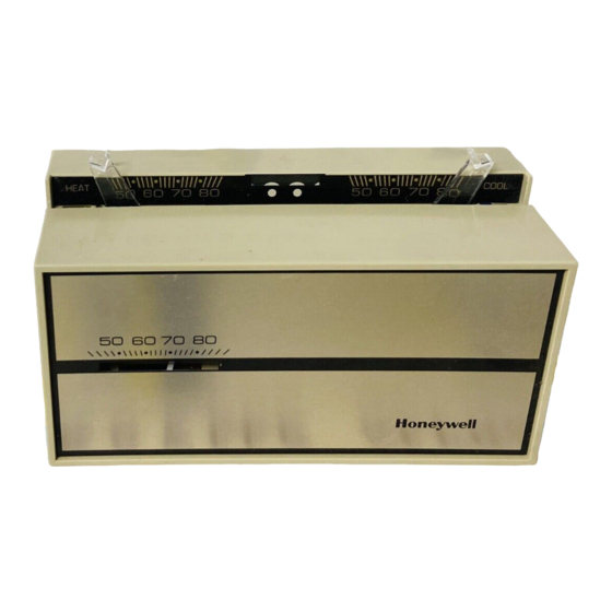
Honeywell T874R Installation Instructions Manual
Hide thumbs
Also See for T874R:
- Installation instructions manual (13 pages) ,
- Installation instructions manual (6 pages) ,
- Installation instructions manual (12 pages)
Table of Contents
Advertisement
T874R Thermostats and Q674L Subbases
TRADELINE
APPLICATION
The T874R Therm ostat and Q 674L Subbase p ro vid e 24 to 30 Vac co n tro l o f 2-stage h eatin g and 1-stag e co o l-in g h eat
p u m p system s w ith m anual changeover. Q 674L Subbase p rovid es EM .HT.-HEAT-OFF-COOL system sw itch in g and
A U TO -O N fan sw itch in g . See Table 1 fo r specific T874R/Q 674L co m b in atio n s.
Therm ostat/
Therm ostat/
Subbase
Subbase
Package
Num bers
Y594R1243
T874R1152/
Q 674L1207
Y594R1300
T874R1475/
Q 674L1520
Y594R1425
T874R1616/
Q 674L1587
Y594R1615
T874R1822/
Q 674L1710
Y594R1664
T874R1871/
Q 674L1736
Y594R1672
T874R1889/
Q 674L1736
T874R1905/
Y594R1698b
Q 674L1777
T874R1913/
Y594R1706b
Q 674L1777
Y594R1763
T874R1954/
Q 674L1827
Y594R1797
T874R1988/
Q 674L1868
a EM .H T. LED also show s com pressor m alfu n ctio n .
b Prem ier W h ite® co lo r.
® U .S. R egistered Tradem ark
Copyright © 1997 Honeywell Inc.
Installation Instructions for the Trained Service Technician.
•
Table 1. Thermostat/Subbase Specifications.
Model
LED
Indication
AU X.H T.,
EM . H T .
AU X.H T.,
EM . H T.a
AU X.H T.,
EM . H T .,
CHECK
AU X.H T.,
EM . H T .,
CHECK
EM . H T .
EM . H T .
EM . H T .
EM . H T .
AU X.H T.,
EM . H T.a
AU X.H T.,
EM .H T.
All Rights Reserved
INSTALLATION INSTRUCTIONS
Changeover
M anual C o o l
TRADELINE® ; adjustable stage 2
heat an ticip atio n . Fixed anticip atio n
in stage 1 . A u to fan in EM .H T.
M anual H eat
TRADELINE® ; fixed h eat
o r Co ol
an ticip atio n . A u to fan in EM .H T.
M anual H eat
SUPER TRADELINE® ; fixed h eat
o r Co ol
an ticip atio n . Factory installed jum p er
across W 1 and Y1. A u to fan in
EM .H T.
M anual H eat
TRADELINE® ; fixed h eat
o r Co ol
an ticip atio n . A u to fan in EM .H T.
M anual C o o l
TRADELINE® ; exact replacem ent
fo r York m o d el n o . 2TH 11702224.
M anual C o o l
TRADELINE® ; exact replacem ent
fo r York m o d el nos. 2TH 11702324
and 6TH 11702224.
M anual C o o l
TRADELINE® ; exact replacem ent
fo r York m o d el nos. 2TH 11702324
and 6TH 11702224. Includes
C815A1054 O utdo or Therm istor.
M anual C o o l
TRADELINE® ; exact replacem ent
fo r York m o d el n o . 2TH 11702224.
M anual C o o l
Requires C815A O utd o or Therm ister
fo r o u td o o r reset. Fixed stage 1 h eat
an ticip atio n . N o heat anticip ation in
stage 2 h eat. A u to fan in EM .H T.
Replaces Y594R1136.
M anual H eat
TRADELINE®
o r Co ol
Honeywell
Com ments
6 9 -0 3 9 2 -9
See
Fig.
6
7
8
1 0
9
1 1
1 1
9
5
1 2
Advertisement
Table of Contents

Related Manuals for Honeywell T874R


Summary of Contents for Honeywell T874R
- Page 1 APPLICATION The T874R Therm ostat and Q 674L Subbase p ro vid e 24 to 30 Vac co n tro l o f 2-stage h eatin g and 1-stag e co o l-in g h eat p u m p system s w ith m anual changeover. Q 674L Subbase p rovid es EM .HT.-HEAT-OFF-COOL system sw itch in g and A U TO -O N fan sw itch in g .
-
Page 2: Mounting The Subbase
T874R THERMOSTATS AND Q674L SUBBASES A CAUTION OPERATION D is c o n n e c t p o w e r s u p p ly to p r e v e n t e le c t r ic a l... - Page 3 T874R THERMOSTATS AND Q674L SUBBASES 4. Secure th e cover p late (if used) and subbase w ith th e screw s p ro vid ed . D o n o t fu lly tig h te n th e subbase screw s.
- Page 4 T874R THERMOSTATS AND Q674L SUBBASES THERMO STAT SUBBASE SYSTEM COM PONENTS Fig. 5. Internal schem atic and typical wiring diagram for Y594R1763 (T874R1954/Q674L1827). Replaces GE AY28X078, AY28X139; Trane Baystat 139, Baystat 239 and Baystat 240; and Honeywell Y594R1136 Therm ostats.
- Page 5 T874R THERMOSTATS AND Q674L SUBBASES THERMOSTAT SUBBASE SYSTEM COMPONENTS (HOT) Fig. 7. Internal schematic and typical wiring diagram for Y594R1300 (T874R1475/Q674L1520); fixed anticipation. T HERMOSTA.T SUBBASE SYSTEM COMPONENTS ------ A---------------- . / -------------------------------------- A-------------------------------------------- . y----------------A------------ Fig. 8. Internal schematic and typical wiring diagram for Y594R1425 (T874R1616/Q674L1587). SUPER TRADELINE®;...
- Page 6 T874R THERMOSTATS AND Q674L SUBBASES SYSTEM COM PONENTS IH E R M O S IA I SUBBASE _ _ _ _ A_ _ _ _ ____A _ _ _ _ _ _ _ _ _ _ _ _ _ A _ (HOT) "...
- Page 7 T874R THERMOSTATS AND Q674L SUBBASES SYSTEM COMPONENTS SUBBASE IH E R M O S IA I _ _ _ _ A_ _ _ _ _ _ _ A_ _ _ _ _ _ _ _ _ _ _ _ _ A _ _ _ _ _ _ _ _ _ _ _ _ _ (HOT) Fig.
-
Page 8: Temperature Setting
T874R THERMOSTATS AND Q674L SUBBASES 1 . Connect an ac am m eter o f ap p ro p riate ran g e Mounting the Thermostat betw een th e h eatin g term inals o f th e subbase: 1 . -
Page 9: Emergency Heat
T874R THERMOSTATS AND Q674L SUBBASES CHECKOUT CALIBRATION Heating Thermostat M o ve th e system sw itch o n th e Q 674 Subbase to H EA T. T874 Therm ostats are accurately calib rated at th e facto ry. - Page 10 69-0392— 9...
- Page 11 69-0392— 9...
- Page 12 Honeywell A utom ation and Control Solutions Honeywell International Inc. Honeywell Limited— Honeywell Limitée 1985 Douglas Drive North 35 Dynamic Drive Golden Valley, MN 55422 Scarborough, Ontario M1V 4Z9 Printed In U.S.A. on recycled paper containing a t least 10% 69-0392—...