Table of Contents
Advertisement
Copyright
Copyright © 2014 MiTAC International Corporation. All rights reserved. No part of
this manual may be reproduced or translated without prior written consent from
MiTAC International Corporation.
Trademark
All registered and unregistered trademarks and company names contained in this
manual are property of their respective owners including, but not limited to the
following.
®
TYAN
is a trademark of MiTAC International Corporation.
®
Intel
is a trademark of Intel
AMI, AMI BIOS are trademarks of AMI Technologies.
®
Microsoft
, Windows
®
Winbond
is a trademark of Winbond Electronics Corporation.
Notice
Information contained in this document is furnished by MiTAC International
Corporation and has been reviewed for accuracy and reliability prior to printing.
MiTAC assumes no liability whatsoever, and disclaims any express or implied
warranty, relating to sale and/or use of TYAN
warranties relating to fitness for a particular purpose or merchantability. MiTAC
retains the right to make changes to product descriptions and/or specifications at
any time, without notice. In no event will MiTAC be held liable for any direct or
indirect, incidental or consequential damage, loss of use, loss of data or other
malady resulting from errors or inaccuracies of information contained in this
document.
S7070
Version 1.0c
®
Corporation.
®
are trademarks of Microsoft Corporation.
http://www.tyan.com
®
products including liability or
1
Advertisement
Table of Contents

Related Manuals for TYAN S7070


Summary of Contents for TYAN S7070
-
Page 1: S7070
Corporation and has been reviewed for accuracy and reliability prior to printing. MiTAC assumes no liability whatsoever, and disclaims any express or implied ® warranty, relating to sale and/or use of TYAN products including liability or warranties relating to fitness for a particular purpose or merchantability. MiTAC retains the right to make changes to product descriptions and/or specifications at any time, without notice. -
Page 2: Table Of Contents
Contents S7070 ......................1 Before you begin… ..................3 Chapter 1: Instruction ................4 1.1 Congratulations ................. 4 1.2 Hardware Specifications ..............4 1.3 Software Specifications ..............12 Chapter 2: Board Installation ..............13 2.1 Board Image ..................14 2.2 Block Diagram ................. 15 2.3 Motherboard Mechanical Drawing ........... -
Page 3: Before You Begin
Check the box contents! The retail motherboard package should contain the following: 1 x S7070 Motherboard 2 x SATA Single Cable 1 x Rear IO shielding 1 x S7070 Quick Installation Guide ® 1 x TYAN Driver CD IMPORTANT NOTE: Sales samples may not come with any of the accessories listed above. -
Page 4: Chapter 1: Instruction
64-bit computing, high-bandwidth memory design, and lightning-fast PCI-E bus implementation. The S7070 not only empowers you in today‟s demanding IT environment but also offers a smooth path for future application upgradeability. All of these rich feature sets provide the S7070 with the power and flexibility to meet demanding requirements for today‟s IT environments. - Page 5 SATA mini-SAS connector Chipset Aspeed AST2400 Monitors voltage for CPU, memory, Voltage chipset & power supply System Total (7) 4-pin headers / Total (1) 2 x Monitoring 10-pin headers Monitors temperature for CPU & Temperature memory & system environment http://www.tyan.com...
- Page 6 - 40° C ~ 70° C (-40° F ~ 158° F) Environment In/Non-operating Humidity 90%, non-condensing at 35° C RoHS RoHS 6/6 Compliant Motherboard (1) S7070 Motherboard Package Manual (1) Quick Installation Guide Contains Installation CD (1) TYAN installation CD...
- Page 7 AST2400 IPMI Feature controller (BMC) / Supports storage over IP and Management remote platform-flash / USB 2.0 virtual hub 24-bit high quality video compression / 10/100 AST2400 iKVM Feature Mb/s MAC interface BIOS Brand / ROM size AMI / 16MB http://www.tyan.com...
- Page 8 - 40° C ~ 70° C (-40° F ~ 158° F) Environment In/Non-operating 90%, non-condensing at 35° C Humidity RoHS RoHS 6/6 Compliant Motherboard (1) S7070 Motherboard Package Manual (1) Quick Installation Guide Contains Installation CD (1) TYAN installation CD TYAN S7070 (S7070WA2NR)
- Page 9 Over temperature warning indicator / Fan & PSU fail LED indicator Others Watchdog timer support Brand / ROM size AMI / 16MB User-configurable H/W monitoring / BIOS Feature SMBIOS 2.7/PnP/Wake on LAN / PXE boot support / ACPI 3.0/ACPI http://www.tyan.com...
- Page 10 - 40° C ~ 70° C (-40° F ~ 158° F) Environment In/Non-operating Humidity 90%, non-condensing at 35° C RoHS RoHS 6/6 Compliant Motherboard (1) S7070 Motherboard Package Manual (1) Quick Installation Guide Contains Installation CD (1) TYAN installation CD...
- Page 11 - 40° C ~ 70° C (-40° F ~ 158° F) Environment In/Non-operating 90%, non-condensing at 35° C Humidity RoHS RoHS 6/6 Compliant Motherboard (1) S7070 Motherboard Package Manual (1) Quick Installation Guide Contains Installation CD (1) TYAN installation CD in bulk packing carton http://www.tyan.com...
-
Page 12: Software Specifications
LSI2308 ALC892 B, R02 Workstation S7070A2NR/MB, ALC892 1.3 Software Specifications For the latest OS (operation system) support, please visit the Tyan‟s Web site for information. Remember to visit our Web site at http://www.tyan.com for the latest AST2400 User‟s Guide. http://www.tyan.com... -
Page 13: Chapter 2: Board Installation
Caution! To avoid damaging the motherboard and associated components, do not use torque force greater than 7kgf/cm (6.09 lb/in) on each mounting screw for motherboard installation. Do not apply power to the board if it has been damaged. http://www.tyan.com... -
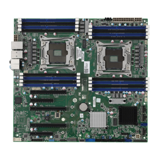
Page 14: Board Image
2.1 Board Image S7070 This picture is representative of the latest board revision available at the time of publishing. The board you receive may not look exactly like the above picture. NOTE: The Slot#5 and M2 NGFF connector are not in SKU channel... -
Page 15: Block Diagram
2.2 Block Diagram S7070 Block Diagram http://www.tyan.com... -
Page 16: Motherboard Mechanical Drawing
2.3 Motherboard Mechanical Drawing http://www.tyan.com... -
Page 17: Board Parts, Jumpers And Connectors
The board you receive may not look exactly like the above diagram. The DIMM slot numbers shown above can be used as a reference when reviewing the DIMM population guidelines shown later in the manual. For the latest board revision, please visit our web site at http://www.tyan.com. http://www.tyan.com... - Page 18 13. IPMB Connector (IPMB1) 32. 4-pin Fan Connector(SYS_FAN3) 14. Front 2.0 USB Header(USB2_2) 33. 4-pin Fan Connector(SYS_FAN2) 15. TYAN Module Header 34. 4-pin Fan Connector (CPU0_FAN) 16. TYPE_A USB Header(A_USB1) 35. 4-pin Fan Connector ( SYS_FAN1) 17. Front 3.0 USB Header(USB3_2) 36.
- Page 19 PSMI1 SYS_FAN1 CPU0_FAN CPU1_FAN SYS_FAN4 SYS_FAN2 SYS_FAN5 SYS_FAN3 SGPIO2 FAN_HDR1 USB2_2 USB3_2 FPIO COM1 A_USB1 IPMB1 http://www.tyan.com...
- Page 20 PWRLED- ID_LED- HDDLED+ HWM_FAULT_LED- HDDLED- SYS_FAULT_LED- PWR_SW# LAN1_ACTLE+ LAN1_ACTLED- RST_SW# SMBDATA SMBCLK FP_IDLED_BTN_N INTRUSION# FPIO_TEMP_IN LAN2_ACTLED+ NMI_SW# LAN2_ACTLED- PSIMI1: PSMI Connector Signal SMB_CLK SMB_DAT SMB_ALERT# V3P3 USB2_2: Front USB2.0 Header Signal Signal USB DATA1- USB DATA2- USBDATA1+ USB DATA2+ http://www.tyan.com...
- Page 21 Signal Signal TACH1 TACH6 TACH2 TACH7 TACH3 TACH8 TACH4 TACH9 TACH5 TACH10 PWM2 PWM1 TACH11 SMB_DATA TACH12 SMB_CLK VCC3_AUX PWM3 SGPIO2: SSATA SGPIO Header Signal Signal SSDATA OUT- SSLOAD SSCLOCK P3V3_AUX HD_ERROR_LED NOTE: SGPIO2 is responsible for SSATA 0~3 http://www.tyan.com...
- Page 22 3PHD_2 2PHD_1 3PHD_1 DBG_HD1 2PHD_2 Caution: The jumpers are only using for engineering debug. We don‟t suggest customers change the jumpers‟ position, which may cause unable to boot device. http://www.tyan.com...
- Page 23 DBG_HD1: TYAN Module Header Signal Signal P3V3 FRAME_N LAD0 LAD1 PLT_RST_N LAD2 LAD3 CLK_33M DBG_SERIRQ DBG_PRES_N VCC3_AUX ADDR_MB PCH_PP_EN 2PHD_1: Chassis Intrusion Header Signal INTRUDER# Open Open: Use this header to trigger the system chassis intrusion alarm. Short: Use this header to disable the system Short (Default) chassis intrusion alarm.
- Page 24 4PHD_12 3PHD_4 3PHD_10 3PHD_8 http://www.tyan.com...
- Page 25 Pin 1-2 Closed: Enable (Default) Pin 2-3 Closed: Disable PSU Alert 4PHD_12: BUZZER Disable Jumper Signal Signal VCC5 BUZ_1 BUZ_2 Pin 3-4 Closed: Normal Mode (Default) Pin 2-3 Closed: Disable PC Beep Pin 1-4 Closed: Use the External Speaker http://www.tyan.com...
- Page 26 ID_LED Button ID_LED SATA4 SATA5 SSATA3/SSATA2/SSATA1/SSATA0 http://www.tyan.com...
- Page 27 P3V3_AUX ID_SW_L State Color Description Blue System identified System not identified NOTE: The ID LED can be activated remotely using IPMI. Please visit the TYAN Web Site at http://www.tyan.com to download the latest IPMI Configuration Guide for more details. http://www.tyan.com...
-
Page 28: Installing The Processor And Heatsink
2.5 Installing the Processor and Heatsink The types of processors supported by the S7070 are listed in the 1.2 Hardware Specifications section on page 4. Check our website at http://www.tyan.com ® the latest list of validated Intel processors for this specific motherboard. - Page 29 Lift the socket cover to a fully open position. Place the CPU in the CPU socket and make sure that the gold arrow is located in the right direction with two notches properly aligned. Remove the socket protection cap. Close the CPU socket cover. http://www.tyan.com...
- Page 30 Close the socket one side lever. Close the socket other side lever. http://www.tyan.com...
- Page 31 . Please refer to the Intel website: http://www.intel.com ® The following diagram illustrates how to install the heatsink on the Intel Haswell EP Socket R3: Tear down the heatsink protective cover. Place the heat sink on top of the CPU. http://www.tyan.com...
- Page 32 Secure the heatsink screws. Connect the fan cable. http://www.tyan.com...
-
Page 33: Thermal Interface Material
CPU lid (applying too much will actually reduce the cooling). NOTE: Always check with the manufacturer of the heat sink & processor to ensure that the thermal interface material is compatible with the processor and meets the manufacturer‟s warranty requirements. http://www.tyan.com... -
Page 34: Tips On Installing Motherboard In Chassis
Be especially careful to look for extra stand-offs. If there are any stand-offs present that are not aligned with a mounting hole on the motherboard, it will likely short components on the back of the motherboard when installed. This will cause malfunction and/or damage to your motherboard. http://www.tyan.com... - Page 35 Some chassis include plastic studs instead of metal. Although the plastic studs are usable, MiTAC recommends using metal studs with screws that will fasten the motherboard more securely in place. Below is a chart detailing what the most common motherboard studs look like and how they should be installed. http://www.tyan.com...
-
Page 36: Installing The Memory
2.8 Installing the Memory Before installing memory, ensure that the memory you have is compatible with the motherboard and processor. Check the TYAN Web site at http://www.tyan.com for details of the type of memory recommended for your motherboard. ® ... - Page 37 3. Populate the same DIMM type in each channel, specifically - Use the same DIMM size - Use the same # of ranks per DIMM 4. Dual-rank DIMMs are recommended over single-rank DIMMs. http://www.tyan.com...
- Page 38 3. Populate the same DIMM type in each channel, specifically - Use the same DIMM size - Use the same # of ranks per DIMM 4. Dual-rank DIMMs are recommended over single-rank DIMMs. http://www.tyan.com...
- Page 39 Intel Xeon processor E5-2600v3 product families Support NOTE 1: 1DPC => One dimm per channel NOTE 2: 2DPC => Two dimm per channel Physical Ranks are used to calculate DIMM Capacity. Supported DRAM Densities are 4Gb, 8Gb. http://www.tyan.com...
-
Page 40: Memory Installation Procedure
Memory Installation Procedure Follow these instructions to install memory modules into the S7070. Unlock a DIMM socket by Press the retaining clip outwardly in the following illustration. Align the memory module with the socket,such that the DIMM NOTCH match the KEY SLOT on the socket. -
Page 41: Attaching Drive Cables
SATA/SAS cables or power adapters please contact your local sales representative. Attaching SAS Cables The following illustrates how to make a SAS Cable connection. If you are in need of SATA/SAS cables or power adapters please contact your local sales representative. http://www.tyan.com... -
Page 42: Installing Add-In Cards
Doing so allows air to circulate within the chassis more easily, thus improving cooling for all installed devices. NOTE: You must always unplug the power connector from the motherboard before performing system hardware changes to avoid damaging the board or expansion device. http://www.tyan.com... -
Page 43: Connecting External Devices
See the following diagrams for the details. LAN2 (shared LAN1 (i350) with IPMI, i350) AST2400, i350 only server) VGA Port ID_Button (only server) Audio Jack with USB2.0x2 USB3.0x2 S/PDIF (only WS) Audio Jack Definition http://www.tyan.com... - Page 44 1Gbps LAN Link/Activity LED Scheme Left LED Right LED Description (Link/Activity) (Speed) No Link Link Green 10 Mbps Active Blinking Green Link Green Solid Green 100 Mbps Active Blinking Green Solid Green Link Green Solid Amber 1Gbps Active Blinking Green Solid Amber http://www.tyan.com...
-
Page 45: Installing The Power Supply
2.12 Installing the Power Supply There are Four (4) power connectors on your S7070 motherboard. The S7070 supports EPS 12V power supply. PWR1: ATX 24-Pin Power Connector Signal Signal V3P3 V3P3 V3P3 -12V PS_ON# PWROK 5VSB +12V +12V V3P3 PWR2: SSI 8-Pin CPU/DIMM Power Connector... -
Page 46: Finishing Up
In the rare circumstance that you have experienced difficulty, you can find help by asking your vendor for assistance. If they are not available for assistance, please find setup information and documentation online at our website or by calling your vendor‟s support line. http://www.tyan.com... -
Page 47: Chapter 3: Bios Setup
Select the previous value/setting of the field <+> Select the next value/setting of the field <F8> Load Fail Safe default configuration values of the menu <F3> Load the Optimal default configuration values of the menu <F4> Save and exit <Enter> Execute command or select submenu http://www.tyan.com... - Page 48 BIOS menus are continually changing due to continual BIOS updates over the product lifespan of the motherboard. The BIOS menus provided are current as of the date when this manual was written. Please visit TYAN‟s website at http://www.tyan.com for information on BIOS updates available for this specific motherboard.
-
Page 49: Main Menu
It displays BIOS related information. Memory Information This displays the total memory size. System Date Adjust the system date. MM (Months): DD (Days): YYYY (Years) System Time Adjust the system clock. HH (24 hours format): MM (Minutes): SS (Seconds) Access Level Read only. http://www.tyan.com... -
Page 50: Advanced Menu
ACPI Settings System ACPI Parameters. Hardware Health Configuration Hardware health Configuration Parameters. Onboard Device Configuration Onboard Device Configuration. PCIe Slot Configuration Onboard PCIe Slot Configuration WatchDog Timer Configuration WatchDog Configuration ASPEED Super IO Configuration System Super IO Chip parameters http://www.tyan.com... - Page 51 PCI, PCI-X and PCI Express Settings CSM Configuration CSM Configuration, Enable/Disable Option ROM execution setting,etc Trusted Computing (optional function) Trusted Computing (TPM) settings. NOTE: If no TPM chipset is on, the Trusted Computing submenu will not appear. USB Configuration USB Configuration Parameters. http://www.tyan.com...
- Page 52 3.3.1 ACPI Settings Enable ACPI Auto Configuration Enable or disable BIOS ACPI Auto Configuration. Disabled / Enabled Enable Hibernation Enables or disables System ability to Hibernate (OS/S4 Sleep State). This option may not be effective with some OS. Disabled / Enabled http://www.tyan.com...
- Page 53 PWM Minimal Duty Cycle Duty Cycle control range 30% Duty Cycle / 45% Duty Cycle / 60% Duty Cycle BMC Alert Beep BMC Alert Beep On/Off. On / Off PSU Status Monitor PMBus support Disabled / Enabled http://www.tyan.com...
- Page 54 3.3.2.1 Sensor Data Register Monitoring When you enter the Sensor Data Register Monitoring submenu, you will see the following dialog window pop out. Please wait 8~10 seconds. NOTE 1: SDR can not be modified. Read only. http://www.tyan.com...
- Page 55 http://www.tyan.com...
- Page 56 http://www.tyan.com...
- Page 57 The ISCSI function is only supported in LAN1. Onboard LSI SAS Enable or disable Onboard LSI SAS Controller Enabled / Disabled Chassis Intrusion detect Enabled: When a chassis open event is detected ,the BIOS will record the event. Disabled / PXE http://www.tyan.com...
- Page 58 NMI Button Enable or disable NMI button. Enabled / Disabled Wait For ‘ESC’ if Error Enable or disable wait ESC key function. When chassis intrusion. CMOS Clear or BMC not Response. Enabled / Disabled http://www.tyan.com...
- Page 59 3.3.4 PCIe Slot Configuration PCIe SLOT1/2/3/5 OPTROM Enabled/Disabled Load OPTROM for PCIe slot devices. Enabled / Disabled PCIe SLOT1/2/3/5 LINK SPEED Onboard PCIe Link Slot Link, Speed Configuration Auto / GEN1(2.5GT/s) / GEN2(5GT/s) / GEN3(8GT/s) http://www.tyan.com...
- Page 60 3.3.5 Watchdog Timer Configuration Watch Dog Mode Watch Dog Mode Help. Disabled / POST / OS / PowerON NOTE: Watch Dog Timer will appear when Watch Dog Mode is not set to [Disabled]. Watch Dog Timer Watch Dog Timer Help. http://www.tyan.com...
- Page 61 3.3.6 ASPEED Super IO Configuration Super IO Chip Read only. http://www.tyan.com...
- Page 62 / IO=3F8h, IRQ=3, 4, 5, 6, 7, 9, 10, 11, 12; / IO=2F8h; IRQ=3, 4, 5, 6, 7, 9, 10, 11, 12; / IO=3E8h, IRQ=3, 4, 5, 6, 7, 9, 10, 11, 12; / IO=2E8h, IRQ=3, 4, 5, 6, 7, 9, 10, 11, 12; http://www.tyan.com...
- Page 63 Wake system from S5 Enable or disable system wake on alarm event. Select Fixed time, system will wake on the hr::min::sec specified. Select dynamic time, system will wake on the current time+ increase minute(s) Disabled / Fixed time /Dynamic time http://www.tyan.com...
- Page 64 Console Redirection Settings The settings specify how the host computer (which the user is using) will exchange data. Both computers should have the same or compatible settings. NOTE: Console Redirection Settings menu only appear when Console Redirection was set to [Enabled]. http://www.tyan.com...
- Page 65 1‟s in the data bits is odd. Mark: parity bit is always 1. Space: parity bit is always 0. Mark and Space parity do not allow for error detection. None / Even / Odd / Mark / Space http://www.tyan.com...
- Page 66 VT100 / LINUX / XTERMR6 / SCO / ESCN / VT400 Redirection After BIOS POST The settings specify if bootloader is selected than Legacy console redirection is disabled before booting to Legacy OS. Default value is always enable means Legacy. Always enable / Bootloader http://www.tyan.com...
- Page 67 3.3.8.2 Console Redirection Settings Legacy Serial Redirection Port Select a COM port to display redirection of Legacy OS and Legacy OPROM Messages COM1 http://www.tyan.com...
- Page 68 115200 / 9600 / 19200 / 38400 / 57600 Flow Control Flow Control can prevent data loss from buffer overflow. When sending data, if the receiving buffers are full, a „stop‟ signal can be sent to stop the data flow. Once the http://www.tyan.com...
- Page 69 „start‟ signal can be sent to restart the flow. Hardware flow control uses two wires to send start/stop signal. None / Hardware RTS/CTS Data Bits / Parity / Stop Bits Read only. http://www.tyan.com...
- Page 70 3.3.9 PCI Subsystem Above 4G Decoding Enables or Disables 64bit capable Devices to be decoded in Above 4G Address Space(Only if System supports 64 bit PCI decoding). Enable / Disabled SR-IOV Supporting Enable / Disabled http://www.tyan.com...
- Page 71 3.3.9.1 PCI Express settings Maximum Payload Set maximum payload of PCI express device or allow system BIOS to select the value. Auto / 128 Bytes / 256 Bytes / 512 Bytes / 1024 Bytes /2048 Bytes / 4056 Bytes http://www.tyan.com...
- Page 72 If supported by hardware and set to ‟Enabled‟, the downstream Port disables its traditional. Device Number field being 0 enforcement when turning a type1 configuration request into a type0 configuration request permitting access to extended functions in an ARI Device immediately below the port. Enabled / Disabled http://www.tyan.com...
- Page 73 Do not launch / UEFI / legacy Storage Controls the execution of UEFI and legacy PXE OpROM Do not launch / UEFI / legacy / Video Controls the execution of UEFI and legacy PXE OpROM Do not launch / UEFI / legacy http://www.tyan.com...
- Page 74 Other PCI devices Determines OpRom execution policy for devices other than network, storage, or video legacy / UEFI http://www.tyan.com...
- Page 75 The following BIOS items are available only when Security Device Support is set to [Enable]. TPM State Enable/Disable security Device. NOTE: Your computer will reboot during restart in order to change State of the device. Enabled / Disabled Current Status Information Read only. http://www.tyan.com...
- Page 76 EHCI driver. Enabled / Disabled USB Mass Storage Driver Support Enabled / Disabled Port 60/64 Emulation Enables I/O port 60h/64h emulation support. This should be enabled for the complete USB keyboard legacy support for non-USB aware OSes. Enabled / Disabled http://www.tyan.com...
- Page 77 Maximum time the device will take before it properly reports itself to the Host Controller. AUTO uses default value: for a Root port it is 100 ms, for a Hub port the delay is taken from Hub descriptor. Auto / Manual http://www.tyan.com...
-
Page 78: Intel Rcsetup Menu
3.4 Intel RCSetup Menu Processor Configuration Processor Parameters. Advanced Power Management Configuration Advanced power management Parameters. Common RefCode Configuration Common RefCode Configuration. QPI Configuration QPI Configuration Memory Configuration Memory Configuration I/O Configuration (I/O Configuration) PCH Configuration (PCH Configuration) Miscellaneous Configuration (Miscellaneous Configuration) http://www.tyan.com... - Page 79 OS (Windows Server 2003 SP1, Windows XP SP2, SuSE Linux 9.2, RedHat Enterprise 3 Update 3). Enabled Disabled Enables the Vanderpool Technology, takes effect after reboot Enabled Disabled Enable SMX Enables Safer Mode Extensions. Enabled Disabled http://www.tyan.com...
- Page 80 3.4.1.1 CPU Socket0/1 Configuration Read only http://www.tyan.com...
- Page 81 http://www.tyan.com...
- Page 82 3.4.2 Advanced Power Management Configuration Power Technology Enable the power management features. Custom / Disabled / Energy Efficient NOTE: The following BIOS items are available only when Power Technology is set to [Custom]. http://www.tyan.com...
- Page 83 When enabled,OS sets CPU frequency according load. When disabled, CPU frequency is set at max non-turbo. Enabled Disabled Turbo Mode Turbo mode allows a CPU logical processor to execute a higher frequency when Enough power is available not exceed CPU defined limits. Enabled Disabled http://www.tyan.com...
- Page 84 Enable/Disable CPU C3 (ACPI C2) report to OS. Recommended to be disabled Enabled / Disabled CPU C6 Report Enable/Disable CPU C6 (ACPI C3) report to OS. Enabled / Disabled Enhanced Halt State Enables the Enhanced C1E state of the CPU, takes effect after reboot Enabled / Disabled http://www.tyan.com...
- Page 85 MMIOHBase MMIOH Base [63:32]; must be between 4032 - 4078 56T / 48T / 24T MMIO High Size Select MMIO High Size 256G /128G / 512G /1024G Numa Enable or Disable none uniform Memory Access. (NUMA) Enabled / Disabled http://www.tyan.com...
- Page 86 Select the QPI Link Frequency. Auto / 6.4GT/s / 9.6GT/s / 8.0GT/s / Auto Limited Link L0p Enable Link L0p Enable: Disable, Enable, Auto (default) Enabled / Disabled Link L1 Enable Link L1 Enable: Disable, Enable, Auto (default) Enabled / Disabled http://www.tyan.com...
- Page 87 3.4.3.1 QPI Status Submenu Read only http://www.tyan.com...
- Page 88 /2667 / Reserved / Reserved / Reserved / Reserved ECC Support Select the memory type supported by this platform. Auto / Disabled / Enabled Memory Type RDIMMs only / UDIMMs only / UDIMMs and RDIMMs Data Scrambling Enables Data Scrambling Auto / Disabled / Enabled http://www.tyan.com...
- Page 89 3.4.4.1 Memory Topology Configuration Read only http://www.tyan.com...
- Page 90 3.4.4.2 Memory Thermal Configuration Set Throttling Mode Configure Thermal throttling mode. Select OLTT or CLTT mode. Disabled / CLTT / OLTT http://www.tyan.com...
- Page 91 3.4.4.3 Memory Map Configuration Channel Interleaving Select Channel Interleaving setting Auto / 1-way Interleave / 2-way Interleave / 3-way Interleave / 4-way Interleave Rank Interleaving Select rank Interleaving setting Auto / 1-way Interleave / 2-way Interleave / 4-way Interleave / 8-way Interleave http://www.tyan.com...
- Page 92 Disabled / Mirror / Lockstep Mode Lockstep x4 DIMMs Enable / Disable Lockstep for x4 DIMMs Auto / Disabled / Enabled Memory Rank Sparing Enable / Disable Memory Rank Sparing Disabled / Enabled Device Tagging Enable / Disable Device Tagging Disabled / Enabled http://www.tyan.com...
- Page 93 3.4.5 I/O Configuration Submenu Read only http://www.tyan.com...
- Page 94 3.4.5.1 IOAT Configuration Submenu Enable IOAT Control to enable / disable IOAT devices Disabled / Enabled http://www.tyan.com...
- Page 95 ® 3.4.5.2 Intel VT for Directed I/O Configuration Submenu ® Intel VT for directed I/O (VT-d) ® Enable/Disable Intel I/O Acceleration Technology (I/OAT). Disabled / Enabled http://www.tyan.com...
- Page 96 3.4.6 PCH Configuration http://www.tyan.com...
- Page 97 3.4.6.1 PCH Devices Configuration PCH State after G3 Select S0/S5 for ACPI state after a G3. S0 / S5 / Last State http://www.tyan.com...
- Page 98 3.4.6.2 PCH sSATA Configuration http://www.tyan.com...
- Page 99 Enable/Disable SATA Ports Hot Plug Support. Disabled / Enabled Spin Up Device AHCI Supports Staggered Spin-up Disabled / Enabled sSATA Device Type Indentify the SATA port is connected to Solid State Drive or Hard Disk Drive Hard Disk Drive / Solid State Drive http://www.tyan.com...
- Page 100 3.4.6.3 PCH SATA Configuration http://www.tyan.com...
- Page 101 Enable/Disable SATA Ports Hot Plug Support. Disabled / Enabled Spin Up Device AHCI Supports Staggered Spin-up Disabled / Enabled SATA Device Type Indentify the SATA port is connected to Solid State Drive or Hard Disk Drive Hard Disk Drive / Solid State Drive http://www.tyan.com...
- Page 102 3.4.6.4 USB Configuration xHCI Mode Mode of operation of xHCI controller. Auto / Smart Auto / Enabled / Disabled / Manual http://www.tyan.com...
- Page 103 3.4.7 Miscellaneous Configuration Active Video Select active video type Onboard Device / Offboard Device http://www.tyan.com...
-
Page 104: Server Management
3.5 Server Management Press <Enter> to change the SEL configuration. Enable/Disable interfaces to communicate with BMC. http://www.tyan.com... - Page 105 Choose options for reactions to a full SEL. Do Nothing / Erase Immediately Log EFI Status Codes Disable the logging of EFI Status Codes or log only error code or only progress code or both. Both / Disabled / Error Code / Progress Code http://www.tyan.com...
- Page 106 3.5.2 BMC Network Configuration Configuration Address Source Select the configure LAN channel parameters statically or dynamically (by BIOS or BMC). Unspecified option will not modify any BMC network parameters during BIOS phase. Current Setting / Static / Dynamic-Obtained by BMC http://www.tyan.com...
-
Page 107: Security
3.6 Security Password Description Read only. Administrator Password Install or change the password. User Password Install or change the password. http://www.tyan.com... - Page 108 3.6.1 Security Flash update Configuration http://www.tyan.com...
-
Page 109: Boot
Select the keyboard NumLock state. Off / On Quiet Boot Enable or disable Quiet Boot option. Disabled / Enabled Endless Boot Enable or disable Endless Boot. Disabled / Enabled Boot Option #1/Boot Option #2 Select the first boot device. Device Name / Disabled http://www.tyan.com... - Page 110 3.7.1 Delete Boot Option Configuration Delete Boot Option #1 Sets the system boot order. Device Name / Select one to Delete http://www.tyan.com...
-
Page 111: Save & Exit
Discard Changes and Reset Reset system setup without saving any changes. Save Options Read only. Save Changes Save changes done so far to any of the setup options. Discard Changes Discard changes done so far to any of the setup options. http://www.tyan.com... - Page 112 Restore Defaults Restore/Load Default values for all the setup options. Save as User Defaults Save the changes done so far as User Defaults. Restore User Defaults Restore the User Defaults to all the setup options. http://www.tyan.com...
-
Page 113: Chapter 4: Diagnostics
BIOS flash failure, you must contact your dealer for a replacement BIOS. There are no exceptions. TYAN does not have a policy for replacing BIOS chips directly with end users. In no event will TYAN be held responsible for damages done by the end user. -
Page 114: Amibios Post Code (Aptio)
South Bridge initialization before microcode loading 0x05 OEM initialization before microcode loading 0x06 Microcode loading 0x07 AP initialization after microcode loading 0x08 North Bridge initialization after microcode loading 0x09 South Bridge initialization after microcode loading 0x0A OEM initialization after microcode loading 0x0B Cache initialization http://www.tyan.com... - Page 115 Memory initialization. Configuring memory 0x2F Memory initialization (other) 0x30 Reserved for ASL (see ASL Status Codes section below) 0x31 Memory Installed 0x32 CPU post-memory initialization is started. 0x33 CPU post-memory initialization. Cache initialization CPU post-memory initialization. Application Processor(s) (AP) 0x34 initialization http://www.tyan.com...
- Page 116 S3 Resume Progress Codes 0xE0 S3 Resume is started (S3 Resume PPI is called by the DXE IPL). 0xE1 S3 Boot Script execution 0xE2 Video repost 0xE3 OS S3 wake vector call 0xE4 – 0xE7 Reserved for future AMI progress codes http://www.tyan.com...
- Page 117 DXEIPL was not found. DXE Core Firmware Volume was not found. Recovery failed S3 Resume failed Reset PPI is not available. DXE Phase Status Code Description 0x60 DXE Core is started. 0x61 NVRAM initialization 0x62 Installation of the South Bridge Runtime Services http://www.tyan.com...
- Page 118 PCI Bus Hot Plug Controller initialization 0x94 PCI Bus Enumeration 0x95 PCI BUS Request Resources 0x96 PCI Bus Assign Resources 0x97 Console output devices connect 0x98 Console Input devices connect 0x99 Super IO initialization 0x9A USB initialization is started. http://www.tyan.com...
- Page 119 0xC0 – 0xCF OEM BDS initialization codes DXE Error Codes 0xD0 CPU initialization error 0xD1 North Bridge initialization error 0xD2 South Bridge initialization error 0xD3 Some of the Architectural Protocols are not available 0xD4 PCI resource allocation error. Out of Resources http://www.tyan.com...
- Page 120 System is waking up from the S3 sleep state. 0x40 System is waking up from the S4 sleep state. System has transitioned into ACPI mode. Interrupt controller is in 0xAC APIC mode. System has transitioned into ACPI mode. Interrupt controller is in 0xAA APIC mode. http://www.tyan.com...
-
Page 121: Appendix I: Fan And Temp Sensors
The red dot indicates the sensor. Fan and Temp Sensor Location: Fan Sensor: It is located in the third pin of the fan connector, which detects the fan speed (rpm) Temp Sensor: PCH_Area_Temp, CPU1_MOS_Temp (RT31) CPU0_MOS_Temp(RT33). They detect the system temperature around. http://www.tyan.com... - Page 122 NOTE: The system temperature is measured in a scale defined by Intel, not in Fahrenheit or Celsius. BIOS Temp Sensor Name Explanation: http://www.tyan.com...
- Page 123 http://www.tyan.com...
- Page 124 Fan speed of SYS_FAN_3 SYS_FAN_4 Fan speed of SYS_FAN_4 SYS_FAN_5 Fan speed of SYS_FAN_5 SYS_FAN_6 Fan speed of SYS_FAN_6 SYS_FAN_7 Fan speed of SYS_FAN_7 SYS_FAN_8 Fan speed of SYS_FAN_8 SYS_FAN_9 Fan speed of SYS_FAN_9 SYS_FAN_10 Fan speed of SYS_FAN_10 http://www.tyan.com...
- Page 125 SYS_FAN_11 Fan speed of SYS_FAN_11 SYS_FAN_12 Fan speed of SYS_FAN_12 http://www.tyan.com...
- Page 126 NOTE http://www.tyan.com...
-
Page 127: Glossary
(reading to or writing from a disk drive a single time is much faster than doing so repeatedly) there is the possibility of losing your data should the system crash. Information in a buffer is temporarily stored, not permanently saved. http://www.tyan.com... - Page 128 (like soundcards or keyboards) to access the main memory without involving the CPU. This frees up CPU resources for other tasks. As with IRQs, it is vital that you do not double up devices on a single line. Plug-n-Play devices will take care of this for you. http://www.tyan.com...
- Page 129 EEPROM (Electrically Erasable Programmable ROM): also called Flash BIOS, it is a ROM chip which can, unlike normal ROM, be updated. This allows you to keep ® up with changes in the BIOS programs without having to buy a new chip. TYAN ‟s BIOS updates can be found at http://www.tyan.com...
- Page 130 PXE (Preboot Execution Environment): one of four components that together make up the Wired for Management 2.0 baseline specification. PXE was designed to define a standard set of preboot protocol services within a client with the goal of allowing networked-based booting to boot using industry standard protocols. http://www.tyan.com...
- Page 131 NVIDIA s (graphics communications processing units) and NVIDIA MCPs (media and processors). application Depending on the , NVIDIA SLI can deliver as much as two times the performance of a single GPU configuration. http://www.tyan.com...
- Page 132 CPUs without damaging the sensitive CPU pins. The CPU is lightly placed in an open ZIF socket, and a lever is pulled down. This shifts the processor over and down, guiding it into the board and locking it into place. http://www.tyan.com...
-
Page 133: Technical Support
"TYAN's tech support is some of the most impressive we've seen, with great response time and exceptional organization in general" - Anandtech.com Help Resources: 1. See the beep codes section of this manual. - Page 134 (RMA) number. The RMA number Should be prominently displayed on the outside of the shipping carton and the package should be mailed prepaid. ® TYAN will pay to have the board shipped back to you. Notice for the USA Compliance Information Statement (Declaration of...