Table of Contents
Advertisement
Copyright
Copyright © MiTAC Computer Corporation, 2009. All rights reserved. No part of
this manual may be reproduced or translated without prior written consent from
MiTAC Computer Corp.
Trademark
All registered and unregistered trademarks and company names contained in
this manual are property of their respective owners including, but not limited to
the following.
®
TYAN
is a trademark of MiTAC Computer Corporation
®
Intel
is a trademark of Intel
®
®
AMI
, AMIBIOS
®
Microsoft
, Windows
®
®
®
IBM
, PC
, AT
and PS/2
®
Winbond
is a trademark of Winbond Electronics Corporation.
Notice
Information contained in this document is furnished by MiTAC Computer
Corporation and has been reviewed for accuracy and reliability prior to printing.
MiTAC assumes no liability whatsoever, and disclaims any express or implied
warranty, relating to sale and/or use of TYAN
warranties relating to fitness for a particular purpose or merchantability. MiTAC
retains the right to make changes to product descriptions and/or specifications
at any time, without notice. In no event will MiTAC be held liable for any direct
or indirect, incidental or consequential damage, loss of use, loss of data or other
malady resulting from errors or inaccuracies of information contained in this
document.
S7002
Version 1.00
®
Corporation.
and combinations thereof are trademarks of AMI Technologies.
®
are trademarks of Microsoft Corporation.
®
are trademarks of IBM Corporation.
®
products including liability or
Advertisement
Table of Contents

Related Manuals for TYAN S7002


Summary of Contents for TYAN S7002
-
Page 1: S7002
Corporation and has been reviewed for accuracy and reliability prior to printing. MiTAC assumes no liability whatsoever, and disclaims any express or implied ® warranty, relating to sale and/or use of TYAN products including liability or warranties relating to fitness for a particular purpose or merchantability. MiTAC retains the right to make changes to product descriptions and/or specifications at any time, without notice. - Page 2 http://www.TYAN.com...
-
Page 3: Table Of Contents
3.10 - Security Menu..................79 3.11 - Chipset Menu ..................80 3.12 - Exit Menu ....................86 Chapter 4: Diagnostics ..............87 4.1 - Beep Codes....................87 4.2 - Flash Utility....................87 4.3 - AMIBIOS Post Code.................88 Appendix: How to Make a Driver Diskette........91 Glossary...................93 Technical Support ................99 http://www.TYAN.com... - Page 4 http://www.TYAN.com...
-
Page 5: Before You Begin
Check the box contents! The retail motherboard package should contain the following: 1x S7002 Motherboard 6 x SATA Cable 1 x S7002 User’s manual 1 x S7002 Quick reference guide ® 1 x TYAN Driver CD 1 x I/O shield http://www.TYAN.com... - Page 6 http://www.TYAN.com...
-
Page 7: Chapter 1: Instruction
PCI-E bus providing a rich feature set and incredible performance. The TYAN S7002 series is designed around several different configurations which are detailed in the following 1.2 Hardware Specification section: 1.2 - Hardware Specifications... - Page 8 - 40° C ~ 70° C (-40° F ~ 158° F) Temp Environment In/Non- operating 90%, non-condensing at 35° C Humidity RoHS 6/6 RoHS Complaint Motherboard (1) TYAN motherboard Accessory list Manual (1) User's manual / (1) Quick Ref. Guide Installation CD (1) TYAN Installation CD http://www.TYAN.com...
- Page 9 (1) CCBL-0615, COM port cable / (1) CCBL-0311, accessories for Cable SATA 1-to-2 power cable / (1) CCBL-035J, USB future upgrade bracket cable TYAN S7002 (S7002WGM2NR/S7002WGP2NR-LE) Intel Xeon 5500 series QC/DC processors Supported CPU Series Socket Type / QTY LGA1366 / (2) Processor...
- Page 10 16MB / AMI size Plug and Play (PnP) /PCI2.3 /WfM2.0 /SMBIOS2.3 /PXE BIOS Boot / ACPI 2.0 power management /Power on mode after Feature power recovery / User-configurable H/W monitoring / Auto- configurable of hard disk types / Multiple boot options http://www.TYAN.com...
- Page 11 Complaint Motherboard (1) TYAN motherboard Manual (1) User's manual / (1) Quick Ref. Guide Accessory list Installation CD (1) TYAN Installation CD I/O Shield (1) I/O Shield Cable (6) SATA signal cables Riser Card M2083-RS, PCI-E 1U riser card (left)
- Page 12 6 channels (3-channel per CPU) Memory voltage 1.5V (1) PCI-E x16 slot (Gen 2) / (2) PCI-E x8 slots (w/ PCI-E x4 link) Expansion Slots Recommended TYAN M2083-RS, PCI-E x16 1U riser card (left) Riser Card Port QTY Controller Intel 82574 Connector Controller...
- Page 13 90%, non-condensing at 35° C Humidity RoHS RoHS 6/6 Complaint Motherboard (1) TYAN motherboard Manual (1) User's manual / (1) Quick Ref. Guide Accessory list Installation CD (1) TYAN Installation CD I/O Shield (1) I/O Shield Cable (6) SATA signal cables http://www.TYAN.com...
- Page 14 Memory voltage 1.5V (1) PCI-E x16 slot (Gen 2) / PCI-E (2) PCI-E x8 slots (w/ x4 Expansion Slots link) M2083-RS, PCI-E x16 1U Recommended TYAN Riser Card riser card (left) Recommended 1U Barebone GT20-B7002 Barebone / Chassis Port QTY...
- Page 15 Plug and Play (PnP) /PCI2.3 /WfM2.0 /SMBIOS2.3 /PXE BIOS Boot / ACPI 2.0 power management /Power on mode Feature after power recovery / Auto-configurable of hard disk types / Multiple boot options Form Factor SSI CEB Form Factor Board 12"x10.5" (305x267mm) Dimension http://www.TYAN.com...
-
Page 16: Software Specifications
’s products with FAQs, online manuals and BIOS upgrades and more. 1.3 - Software Specifications ® For OS (operation system) support, please check the TYAN website for the latest information. 1.4 - AST2050 User Guide Remember to visit TYAN®’s Website at http://www.TYAN.com for AST2050 updated user guide. -
Page 17: Chapter 2: Board Installation
Unplug the power from your computer power supply and then touch a safely grounded object to release static charge (i.e. power ® supply case). For the safest conditions, TYAN recommends wearing a static safety wrist strap. (2) Hold the motherboard by its edges and do not touch the bottom of the board, or flex the board in any way. -
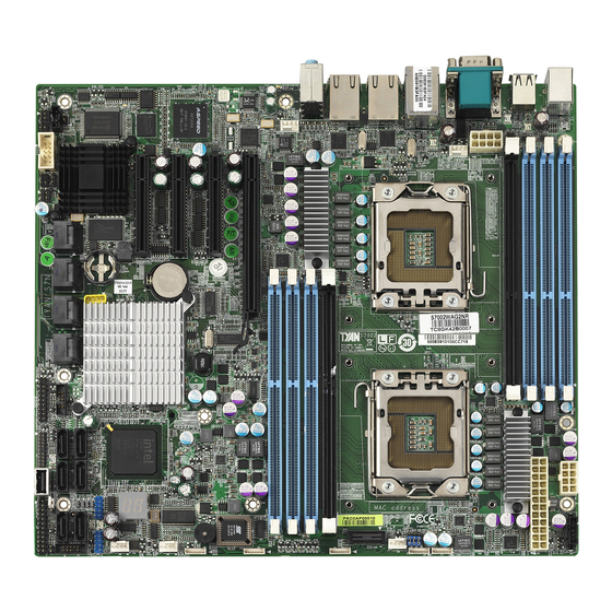
Page 18: Board Image
2.1 - Board Image This diagram is representative of the latest motherboard (S7002WAP2NR) revision available at the time of publishing. The board you receive may not look exactly like the above diagram. http://www.TYAN.com... -
Page 19: Block Diagram
2.2 - Block Diagram S7002 Block Diagram (Represents all SKUs) http://www.TYAN.com... -
Page 20: Board Parts, Jumpers And Connectors
2.3 - Board Parts, Jumpers and Connectors This diagram is representative of the latest board revision (S7002WAP2NR) available at the time of publishing. The board you receive may not look exactly like the above diagram. http://www.TYAN.com... - Page 21 Clear CMOS PSMI Connector IPMB Pin Header J21/J51 SAS SGPIO Header BMC RST Button Clear CMOS On Board SAS LSI1068E EN/DIS JP8/JP9 COM2 Select Jumper Legend OPEN - Jumper OFF Without jumper cover CLOSED - Jumper ON With jumper cover http://www.TYAN.com...
- Page 22 Jumper Placement J36/J37/J40/J41/J42: 4-Pin FAN Connector Signal +12V FAN_TACH FAN_PWM Pin_1 http://www.TYAN.com...
- Page 23 J47/J48/J49/J50/J56: 8-Pin FAN Connector Signal VDD_12_RUN TACHIN Pin_1 Signal TACHIN VDD_12_RUN http://www.TYAN.com...
- Page 24 J16: Com2 Header Signal Signal http://www.TYAN.com...
- Page 25 MIC2-R FP_Present LINE2-R MIC2-JD FP IO Sense LINE2-R LINE2-JD J35: Front Panel Header Signal Signal PW_LED+ FP_PWER(3.3V) ID_ LED+ PW_LED- ID_ LED- HD_ LED+ FAULT_ LED- HD_ LED- FAULT_ LED- PW_SW# LAN1_ACTLE+ LAN1_ACTLE- RST_SW# SYS_ID_SW# INTRUDER# LAN2_ACTLED+ NMI_SW# LAN2_ACTLED- http://www.TYAN.com...
- Page 26 J21/J51 SAS SGPIO Header Signal Signal SDATA IN SDATA OUT- SLOAD SCLOCK HD_ERROR_LED http://www.TYAN.com...
- Page 27 TACH8 TACH4 TACH9 TACH5 TACH10 KEY PIN PWM2 PWM1 TACH11 TACH13 TACH12 TACH14 PWM3 J44: PSMI Connector Signal SMB_CLK SMB_DAT PSU_SMBALERT_N Pin_1 V3.3 J46: IPMB Connector IPMB Signal IPMB CLK Pin_1 DATA J52 BMC RST Button Pin_1 Signal RST# http://www.TYAN.com...
- Page 28 Put jumper cap back to Pin_1 and Pin_2 (default setting) Use jumper cap to close Pin_2 and Pin_3 Pin_1 Pin_3 for several seconds to Clear Clear CMOS CMOS Reconnect power & power on system http://www.TYAN.com...
- Page 29 Onboard ID LED You can identify the specific system using this LED. Users from remote site could also activate ID LED by input a few commands in IPMI, detailed software support please visit http://www.tyan.com lastest AST2050 user guide. Signal P3V3_AUX...
-
Page 30: Installing The Processor
Your brand new S7002 supports the latest Tylersburg platform from Intel ® Only Intel “Nehalem-EP 2S” processors are certified and supported with this motherboard. Check our website for latest processor support. http://www.TYAN.com ® TYAN is not liable for damage as a result of operating an unsupp- -orted configuration. Step1:... - Page 31 Step3: Close the socket cover and press the CPU lever down to secure the CPU. http://www.TYAN.com...
-
Page 32: Heat Sink Installation
Please refer to Intel’ s website at www.Intel.com The following diagram illustrates how to install heat sink onto the CPU of S7002. Place the heat sink on top of the CPU and secure it to the motherboard using four screws clockwise. http://www.TYAN.com... -
Page 33: Thermal Interface Material
CPU lid (applying too much will actually reduce the cooling). Note: Always check with the manufacturer of the heat sink & processor to ensure the thermal Interface material is compatible with processor meets manufacturer’s warranty requirements. http://www.TYAN.com... -
Page 34: Finishing Installing The Heat Sink
(which should already be attached to the heat sink) to the motherboard. The following diagram illustrates how to connect fans onto the motherboard. Once you have finished installing all the fans you can connect your drives (hard drives, CD-ROM drives, etc.) to your motherboard. http://www.TYAN.com... -
Page 35: Tips On Installing Motherboard In Chassis
If you are unsure of stud placement, simply lay the motherboard inside the chassis and align the screw holes of the motherboard to the studs inside the case. If there are any studs missing, you will know right away since the motherboard will not be able to be securely installed. http://www.TYAN.com... - Page 36 Some chassis’ include plastic studs instead of metal. Although the plastic ® studs are usable, TYAN recommends using metal studs with screws that will fasten the motherboard more securely in place. Below is a chart detailing what the most common motherboard studs look like and how they should be installed.
-
Page 37: Installing The Memory
2). Refer to the memory population option table for recommended memory installation instruction. Memory Population Option Table ® To achieve the best performance, TYAN strongly recommended memory installation configuration as listed below: 1. Single CPU installed (CPU0 Only) Quantity of memory... - Page 38 1). “√”indicates a populated DIMM slot. 2). If installing only one processor, you can choose either CPU0 or CPU1. 3). For two slots per channel configuration, it requires population to start with the DIMM slots furthest away from the processor. http://www.TYAN.com...
-
Page 39: Memory Installation Procedure
Hold the DIMM by both of its ends . Insert the module vertically into the socket . Apply force to both ends of the DIMM simultaneously until the retaining clip pop up into place. And the DIMM cannot be pushed in any further to ensure proper sitting of the DIMM。 http://www.TYAN.com... -
Page 40: Attaching Drive Cables
If you are in need of SATA/SAS cables or power adapters please contact your place of purchase. The following pictures illustrate how to connect an SATA drive 1. SATA drive cable connection 2. SATA drive power connection 3. SATA cable motherboard connector 4. SATA drive power adapter http://www.TYAN.com... -
Page 41: Installing Add-In Cards
Doing so allows air to circulate within the chassis more easily, thus improving cooling for all installed devices. Note: YOU MUST ALWAYS unplug the power connector to the motherboard before performing system hardware changes to avoid damaging the board or expansion device. http://www.TYAN.com... -
Page 42: Installing I/O Shield
Use the pliers to grasp and twist the I/O port cap off the shield. Step 3 Repeat Step 1 and 2 as needed to remove the I/O caps to match your specific SKU’s rear I/O configuration and then attach the I/O shield to the rear panel. http://www.TYAN.com... -
Page 43: Connecting External Devices
The chart below illustrates the different LED states. 10/100/1000 Mbps LAN Link/Activity LED Scheme Left LED Right LED Link Green 10 Mbps Active Blinking Green Link Green Green 100 Mbps Active Blinking Green Green Link Green Yellow 1000 Mbps Active Blinking Green Yellow No Link http://www.TYAN.com... -
Page 44: Installing The Power Supply
2.14 - Installing the Power Supply There are three power connectors on your S7002.The S7002 supports EPS- 12V/SSI power supplies. PWR2/3: 8-Pin EPS 12V PWR Connector Signal Signal +12V2 +12V2 +12V3b +12V3b http://www.TYAN.com... -
Page 45: Finishing Up
We suggest using a 1000W or higher power supply. A 1000W is sufficient for most common system configurations, however a higher wattage solution may be needed if the system is fully loaded. Look to the www.TYAN.com website for further information. - Page 46 http://www.TYAN.com...
-
Page 47: Chapter 3: Bios Setup
To configure the advanced chipset features PCI/PnP To configure legacy Plug & Play or PCI settings Boot To configure system boot order Security To configure user and supervisor passwords Chipset To configure chipset management features Exit To exit setup utility http://www.TYAN.com... -
Page 48: Setup Basics
Please be noticed that the BIOS menu are continually changing due to the BIOS updating. The BIOS menu provided are the most updated when this manual is ® written. Please visit TYAN ’s website at http://www.TYAN.com for the information of BIOS updating. 3.6 - BIOS Main Menu http://www.TYAN.com... - Page 49 General Help System Time [HH:MM:SS] F10 Save and Exit System Date [MM:DD:YYYY] ESC Exit Feature Option Description Main System Time HH : MM : SS Set the system time System Date MM : DD : YYYY Set the system date http://www.TYAN.com...
-
Page 50: Bios Advanced Menu
Menu Item Configuration Hardware Health IPMI configuration including IPMI 2.0 Configuration Menu Item server monitoring and event Configure Intel® Virtualization Intel VT-d Configuration Menu Item Technology for Directed I/O (VT-d) support PCI Express Configuration Menu Item Configure PCI Express Support http://www.TYAN.com... -
Page 51: Cpu Configuration
Tech [Enabled] ↑↓ Select Item ® Intel TurboMode Tech [Enabled] Change Option ® Intel C-STATE Tech [Enabled] General Help C State package limit setting [Auto] F10 Save and Exit C1 Auto Demotion [Enabled] ESC Exit C3 Auto Demotion [Enabled] http://www.TYAN.com... - Page 52 Enable (GV3) Tech Disable (GV3) Disabled Enabled Turbo mode allows processor cores ® Intel TurboMode to run faster than marked frequency Tech Disabled in specific condition. Enabled C-State: CPU idle is set to ® Intel C-STATE Tech C2/C3/C4 Disabled http://www.TYAN.com...
- Page 53 Secondary IDE Slave [Not Detected] Third IDE Master [Not Detected] Fourth IDE Master ← → Select Screen ↑↓ Select Item Change Option [Disabled] Hard Disk Write Protect General Help [35] IDE Detect Time Out (Sec) F10 Save and Exit ESC Exit http://www.TYAN.com...
- Page 54 Allows BIOS to Select Serial Port1 Base Addresses. ← → Select Screen ↑↓ Select Item Serial Port1 Address [3F8/IRQ4] Change Option Serial Port2 Address [2F8/IRQ3] General Help Watchdog Mode [Disabled] F10 Save and Exit Chassis intrusion detection [Disabled] ESC Exit http://www.TYAN.com...
- Page 55 BIOS will record the Enabled event and issue a warning Beep. POST: BIOS POST Watchdog timer Disabled counting, start at PowerOn stop at OS POST boot. Watchdog Mode OS boot watchdog, start at OS boot. Power ON PowerOn: Start at PowerOn http://www.TYAN.com...
- Page 56 Enable or disable hotplug USB Disabled floppy support. A dummy FDD device is created that will be Hotplug USB FDD Support Enabled associated with the hotplugged FDD later. AUTO option creates this dummy device only if there AUTO is no USB FDD present. http://www.TYAN.com...
- Page 57 If Auto, USB devices less than 530 Floppy MB will be emulated as Floppy and remaining as hard drive. Forced Emulation Type Forced FDD FDD option can be used to force a HDD formatted drive to boot as FDD Hard Disk (Ex. ZIP drive). CDROM http://www.TYAN.com...
- Page 58 64-bit Fixed System ACPI APIC Support [Enabled] Description Tables. Di AMI OEMB table [Enabled] ACPI version has Headless mode [Disabled] some. ← → Select Screen ↑↓ Select Item Change Option General Help F10 Save and Exit ESC Exit http://www.TYAN.com...
- Page 59 Resume feature, which is generally useless). Disabled Enable/Disable APIC ACPI APIC ACPI SCI IRQ SCI IRQ. Enabled USB Device Wakeup from Disabled Enable/Disable USB Device S3/S4 Wakeup From S3/S4. Enabled High Performance Event Disabled Enable/Disable High Timer Enabled Performance Event Timer http://www.TYAN.com...
- Page 60 F10 Save and Exit AHCI Port5 [Not Detected] ESC Exit Feature Option Description AHCI Configuration Disabled Enable for supporting AHCI. AHCI BIOS Support Enabled Some SATA CD/DVD in AHCI CD/DVD Boot Time AHCI mode need to wait ready longer. http://www.TYAN.com...
- Page 61 F10 Save and Exit ESC Exit Feature Option Description AHCI Port X AUTO Select the type of device SATA Port X connected to the system. Not Installed S.M.A.R.T. stands for Self- Disabled S.M.A.R.T. Monitoring, Analysis and Enabled Reporting Technology. http://www.TYAN.com...
- Page 62 Auto FAN Control Disabled: Fan Power On Enabled: Fan Power Duty Cycle is controlled by Enabled Tcontrol. 50% Duty Cycle Duty Cycle control range: 40% Duty 50%-100% PWM Minimal Duty Cycle Cycle 40%-100% 30%-100% 30% Duty 0%-100% Cycle 0% Duty Cycle http://www.TYAN.com...
- Page 63 Tab Select Field FAN6 : xxxx RPM General Help FAN7 : xxxx RPM F10 Save and Exit FAN8 : xxxx RPM ESC Exit FAN9 : xxxx RPM FAN10 : xxxx RPM Read only. It can not be modified in user mode. http://www.TYAN.com...
- Page 64 BMC Watch Allows the BMC to reset or power down the Reset System Dog Timer system if the operating system crashes or Power Down Action hangs. Power Cycle BMC Alert LED BMC Alert LED and Beep On/Off and Beep http://www.TYAN.com...
- Page 65 PEF Support [Disabled] ← → Select Screen ↑↓ Select Item Change Option Tab Select Field General Help F10 Save and Exit ESC Exit Feature Option Description Set PEF Configuration Parameters Command Disabled PEF Support Enable or Disable PEF Support Enabled http://www.TYAN.com...
- Page 66 Current IP Address in Read only Current MAC Address Read only in BMC Enter Subnet Mask in decimal in the Subnet Mask [xxx.xxx.xxx.xxx] form of xxx.xxx.xxx.xxx. (xxx less than 256 and in decimal only) Current Subnet Mask in Read only http://www.TYAN.com...
- Page 67 Intel VT-d Configuration ® Enable or disable Intel Virtualization Enabled Technology for Directed I/O (VT-d) support. VT-d support on Intel platforms provides the Intel VT-d capability to ensure improved isolation of Disabled I/O resources for greater reliability, security, and availability. http://www.TYAN.com...
- Page 68 [3F8h, 4] General Help Serial Port Mode [38400 8, n, 1] F10 Save and Exit Flow Control [None] ESC Exit Redirection After BIOS POST [Always] Terminal Type [ANSI] VT-UTF8 Combo Key Support [Enabled] Sredir Memory Display Delay [No Delay] http://www.TYAN.com...
- Page 69 VT-UTF8 Enabled VT-UTF8 Combo Key Enable VT-UTF8 Combination key Support Support for ANSI/VT100 terminals. Disabled No Delay Delay 1 Sec Sredir Memory Display Gives the delay in seconds to display Delay memory information Delay 2 Sec Delay 4 Sec http://www.TYAN.com...
- Page 70 (Deactivate) command to TPM Enabled [Press Enter] Select [OK] to clear the TPM or Clearing the TPM See dialog box [Cancel] to exit. below Report TPM Enable/Disable TPM Enable/Disable Status read only status TPM Owner Status read only Report TPM Owner status http://www.TYAN.com...
- Page 71 Onboard Device and PCI Slots Configuration type. Boots Graphic Adapter Priority [Auto] Lan1 [Auto] ← → Select Screen Lan1 OP-ROM [Disabled] ↑↓ Select Item Lan2 [Auto] Change Option Lan2 OP-ROM [Disabled] General Help F10 Save and Exit ESC Exit http://www.TYAN.com...
- Page 72 Onboard Priority device. Auto Lan1 Enable/disable Lan controller Enabled Disabled Enabled Lan1 OP-ROM Executed Lan OPROM or Not Disabled Auto Enabled Lan2 Enable/disable Lan controller Disabled Enabled Lan2 OP-ROM Executed Lan OPROM or Not Disabled http://www.TYAN.com...
-
Page 73: Pci Pnp Menu
When set to higher values, every PCI device PCI Latency Timer can conduct transactions for a longer time and thus improve the effective PCI bandwidth. Values in units of PCI clocks for PCI device latency timer register. http://www.TYAN.com... - Page 74 Enabled: informs the PCI devices that an ISA graphics device is Enabled installed in the system so the card will function correctly. Disabled Enabled: BIOS uses PCI bus PCI IDE BusMaster mastering for reading / writing to Enabled IDE drives. Reserved http://www.TYAN.com...
-
Page 75: Boot Menu
PS/2 Mouse Support [Auto] system. Wait for ‘F1’ if Error [Enabled] Hit ‘DEL’ Message Display [Enabled] Interrupt 19 Capture [Enabled] ← → Select Screen ↑↓ Select Item Endless Boot [Disabled] Change Option General Help F10 Save and Exit ESC Exit http://www.TYAN.com... - Page 76 Displays “Press DEL to run Setup” Display in POST. Disabled Enabled PXE feature Enable/Disable PXE Oprm Scan Disabled Enabled Enabled: allows option ROMs to Interrupt 19 Capture trap interrupt 19. Disabled Disabled Enable/Disable endless loop boot Endless Boot Enabled from BBS table. http://www.TYAN.com...
-
Page 77: Boot Device Priority
↑↓ Select Item Change Option General Help F10 Save and Exit ESC Exit Feature Option Description Boot Device Priority Settings for boot priority. xx,xxx-xxxxx:xxx 1st Boot Device These 2nd Boot Device customized depending xx,xxx-xxxxx:xxx 3rd Boot Device on your preference. Disabled http://www.TYAN.com... -
Page 78: Hard Disk Drives
1st Drive [xxxxxxxx] ← → Select Screen ↑↓ Select Item Change Option General Help F10 Save and Exit ESC Exit Feature Option Description Hard Disk Drives Specifies the boot xx,xxx-xxxxx:xxx 1st Drive sequence from the available Disabled devices. http://www.TYAN.com... -
Page 79: Security Menu
User Password. When it is set to [Enabled], Disabled BIOS will issue a virus warning Boot Sector Virus message and beep if a write to Protection the boot sector or the partition Enabled table of the HDD is attempted. http://www.TYAN.com... -
Page 80: Chipset Menu
WARNING: Setting wrong values in below sections may cause system to malfunction. CPU Bridge Configuration Northbridge Configuration ← → Select Screen Southbridge Configuration ↑↓ Select Item Enter Go to Sub Screen General Help F10 Save and Exit ESC Exit http://www.TYAN.com... - Page 81 [Enabled] ↑↓ Select Item Inlet temp [070] Enter Go to Sub Screen Temp Rise [020] General Help Air Flow [1500] F10 Save and Exit Altitude [Sea level or below] ESC Exit DIMM Pitch [400] Serial DEBUG Message [None] Level http://www.TYAN.com...
- Page 82 DIMM temp sensor Threshold. (in 0.5°C units) Inlet temp Temperature at the chassis inlet. (in 0.5°C units) Temp Rise Temperature rise to the DIMM thermal zone. (in 0.5°C units) Air speed to the DIMMs. (in Air Flow units of mm/sec) http://www.TYAN.com...
- Page 83 The system altitude above sea Altitude level(in meters) 1201~1500 1501~1800 1801~2100 2101~2400 2401~2700 2701~3000 The pitch between DIMMs.(in DIMM Pitch [400] units of 1/1000 inch) NONE Serial Debug message Specifies what level of debug level messages to display. TEST http://www.TYAN.com...
- Page 84 NB Revision [B0] Current CSI Frequency X.XXXGT ← → Select Screen Crystal Beach/DMA [Disabled] ↑↓ Select Item Change Option General Help F10 Save and Exit ESC Exit Feature Option Description NorthBridge Chipset Configuration Enabled Crystal Beach/DMA Crystal Beach/DMA configuration. Disabled http://www.TYAN.com...
- Page 85 SLP_S4# Min. Assertion Set SLP_S4# Min. Assertion 3 to 4 seconds Width Width. 2 to 3 seconds 1 to 2 seconds Power Off Restore on AC Power System state after Restore on Loss Power On AC Power Loss. Last State http://www.TYAN.com...
-
Page 86: Exit Menu
Use this option to load default performance setup values. Use this option when system CMOS values have been corrupted or modified incorrectly. Load Failsafe Defaults Use this option to load all default failsafe setup values. Use this option when troubleshooting. http://www.TYAN.com... -
Page 87: Chapter 4: Diagnostics
BIOS. There are no ® exceptions. TYAN does not have a policy for replacing ® BIOS chips directly with end users. In no event will TYAN be held responsible for damages done by the end user. http://www.TYAN.com... -
Page 88: Amibios Post Code
ADM module for initialization. Initialize language and font modules for ADM. Activate ADM module. Initializes the silent boot module. Set the window for displaying text information. Displaying sign-on message, CPU information, setup key message, and any OEM specific information. http://www.TYAN.com... - Page 89 Wait for user input at config display if needed. Uninstall POST INT1Ch vector and INT09h vector. Deinitializes the ADM module. Prepare BBS for Int 19 boot. End of POST initialization of chipset registers. Save system context for ACPI. Passes control to OS Loader (typically INT19h). http://www.TYAN.com...
- Page 90 http://www.TYAN.com...
-
Page 91: Appendix: How To Make A Driver Diskette
Appendix: How to Make a Driver Diskette ® Follow the steps below to make a driver diskette from the TYAN driver CD provided. ® Start the system and insert the TYAN CD into the CD-ROM drive to boot from CD. You will see the following menu. Then press [1] and [Enter] to ®... - Page 92 Follow the instruction on menu to insert a diskette and press [ENTER]. Please insert a formatted diskette into A:/ and press [ENTER] Writing image to drive A: Track: 36 Hoad: 8 Sector: 1 ® Using "ESC" key to quit the TYAN diskette maker. The system will automatically restart. http://www.TYAN.com...
-
Page 93: Glossary
The CPU can manipulate data in a buffer before copying it to a disk drive. While this improves system performance (reading to or writing from a disk drive a single time is much faster than doing so repeatedly) there is the possibility of http://www.TYAN.com... - Page 94 CPU. This frees up CPU resources for other tasks. As with IRQs, it is vital that you do not double up devices on a single line. Plug-n-Play devices will take care of this for you. http://www.TYAN.com...
- Page 95 BIOS, it is a ROM chip which can, unlike normal ROM, be updated. This allows you to keep up with changes in the BIOS programs without having to buy a new ® chip. TYAN ’s BIOS updates can be found at http://www.TYAN.com ESCD (Extended System Configuration Data): a format for storing information about Plug-n-Play devices in the system BIOS.
- Page 96 Plug-n-Play require you to reconfigure your system each time you add or change any part of your hardware. PXE (Preboot Execution Environment): one of four components that together make up the Wired for Management 2.0 baseline specification. PXE was http://www.TYAN.com...
- Page 97 SDRAM (Static RAM): unlike DRAM, this type of RAM does not need to be refreshed in order to prevent data loss. Thus, it is faster and more expensive. SLI (Scalable Link Interface): NVIDIA SLI technology links two graphics cards together to provide scalability and increased performance. NVIDIA SLI takes http://www.TYAN.com...
- Page 98 CPUs without damaging the sensitive CPU pins. The CPU is lightly placed in an open ZIF socket, and a lever is pulled down. This shifts the processor over and down, guiding it into the board and locking it into place. http://www.TYAN.com...
-
Page 99: Technical Support
TYAN serves multiple market segments with the industry's most competitive services to support them. "TYAN's tech support is some of the most impressive we've seen, with great response time and exceptional organization in general" ----Anandtech.com Help Resources: 1. - Page 100 Authorization (RMA) number.The RMA number Should be prominently displayed on the outside of the shipping carton and the package should be ® mailed prepaid. TYAN will pay to have the board shipped back to you. Notice for the USA Compliance Information Statement (Declaration of...