
Related Manuals for Paradox Magellan MG5050 EN


Summary of Contents for Paradox Magellan MG5050 EN
- Page 1 MG5000 V4.7 MG5050 V4.7 MG5050 EN V4.96 SP4000 V5.1 SP5500 V4.9 SP6000 V4.9 SP7000 V4.9 Reference & Installation...
-
Page 2: Table Of Contents
Sleep Arming switches to Sleep Force Arming ........ 40 Configuring the Keypad Zone Number ..........17 Restrict Arming on Battery Failure ........... 40 Programming Using A Paradox Memory Key*........17 Restrict Arming on Tamper Failure ..........40 Restrict Arming on Wireless Supervision Trouble ......41 LCD Keypad Labels ............ - Page 3 Closing Delinquency Delay ............... 51 Limitations of Alarm Systems It must be understood that while your Paradox alarm system is highly advanced and Power Failure Report Delay.............. 52 secure, it does not offer any guaranteed protection against burglary, fire or other Report System Disarming..............
-
Page 4: Introduction
Part 1: Introduction Features • 32 zones (any of which can be wireless or keypad zones). • 32 users and 32 remote controls (one per user). • In-field upgrades: Update the panel’s firmware by connecting it to a PC via a 307USB Interface and then using the Winload software (V2.80 or higher). -
Page 5: Specifications
Specifications MG5000 / MG5050 Power rating 16.5 VAC (50 or 60Hz) minimum 20 VA (40 VA recommended) Power consumption MG5000: 1.2A(Max.), 85mA (Idle) MG5050: 1.2A(Max.), 95mA (Idle) Aux. power * 600 mA typical, 700 mA maximum, fuseless shutdown at 1.1A Battery 12 VDC, 4Ah/7Ah Battery charging current... -
Page 6: Installation
Part 2: Installation Location and Mounting Before mounting the cabinet, push the five white nylon mounting studs into the back of the cabinet. Pull all cables into the cabinet and prepare them for connection before mounting the circuit board into the back of the cabinet. Select a centralized installation site on the main floor that isn't easily accessible to intruders and leave at least 5cm (2in) around the panel box to permit adequate ventilation and heat dissipation. -
Page 7: Mg5000 Pcb Layout
Four pin connector lock enabled can be used for quick installation of a "RX" & “TX” LED: MG5000 keypad. Flashes quickly when Paradox Memory receiving or transmitting RF signals Key (PMC-4, from wireless devices. PMC5) Disconnect telephone line before servicing. -
Page 8: Mg5050 / Mg5050 En Pcb Layout
= Installer lock enabled Press and hold the RESET button for five "RX" & “TX” LED: Paradox Memory Key seconds. The STATUS Flashes quickly when (PMC-4, PMC5) LED will start flashing. receiving or transmitting RF... -
Page 9: Sp4000 Pcb Layout
SP4000 PCB Layout Paradox Memory Key (PMC-4, PMC5) EBUS and Dialer used for VDMP3 plug-in voice module for voice reporting. Four pin connector can be used for quick installation of a SP4000 keypad. Used for In-Field Firmware upgrade through a 307USB Direct Connect Interface. -
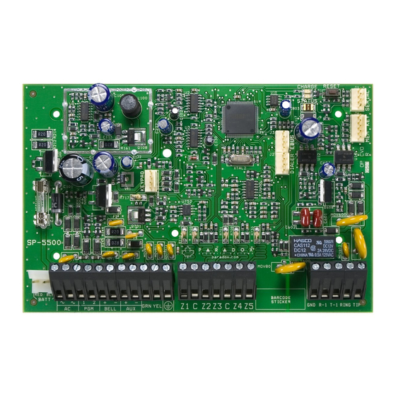
Page 10: Sp5500 Pcb Layout
PGM +/- trigger not VDMP3 plug-in voice module supported by the for voice reporting. SP5500 Paradox Memory Key (PMC-4, PMC5) Press and hold the RESET button for five seconds. The STATUS LED will start flashing. Within 2 seconds of this flashing, press the reset switch again. -
Page 11: Sp6000 Pcb Layout
VDMP3 plug-in voice module state relay PGMs are for voice reporting. grounded (-), or give out 12V (+). Paradox Memory Key (PMC-4, PMC5) Press and hold the RESET button for five seconds. The STATUS LED will start flashing. -
Page 12: Sp7000 Pcb Layout
EBUS and Dialer used for VDMP3 plug-in voice module for voice reporting. Paradox Memory Key PGM Trigger: This jumper allows you (PMC-4, PMC5) to choose whether the solid state relay PGMs are grounded (-), or give out 12V (+). -
Page 13: Metal Box Installation
2.12 Metal Box Installation The crosses and dotted line represent the mounting location. If you need specific dimensions, contact Paradox Distributor Support. For UL recommended installation for the MG5000 only, place the PCB one notch lower than the mounting location. - Page 14 SP5500 (8x10”) SP6000 (11x11”) SP7000 (11x11”) Reference & Installation Manual...
-
Page 15: Auxiliary Power Terminals
2.13 Auxiliary Power Terminals The auxiliary power supply terminals can be used to power motion detectors, keypads and other modules or accessories in the security system. A fuseless circuit protects the power supply against current overload and automatically shuts down if the current exceeds 1.1A. -
Page 16: Single Zone Inputs
2.17 Single Zone Inputs Detection devices such as motion detectors and door contacts are connected to the control panel's zone input terminals. Figure 3 demonstrates single zone input terminal connections recognized by the panel. Once connected, the associated zone's parameters must be defined. Figure 3: Single Zone Input Connections Reference &... -
Page 17: Advanced Technology Zone (Atz) Connections
2.18 Advanced Technology Zone (ATZ) Connections The ATZ feature is a software oriented feature that enables two detection devices to be installed per hardwired input terminal. Each detection device has its own zone, displays its zone status on the keypad and sends its own alarm codes. Fire zones cannot be doubled. -
Page 18: Fire Circuits
2.19 Fire Circuits When a zone is programmed as a fire zone, the zone becomes normally open and requires an EOL resistor. If a line short occurs or if the smoke detector becomes active, whether the system is armed or disarmed, the control panel will generate an alarm. If a trouble occurs on a fire zone, the Fire Loop Trouble will appear in the keypad’s trouble display (see Trouble Display on page 60) and the control panel can transmit the Fire Loop Trouble report, if programmed, in section [866]. -
Page 19: Programming Methods
Program the control panels remotely or on-site using the WinLoad Software (V2.80 or higher) for Windows®. For more information, contact your local Paradox Distributor or visit our web site at paradox.com. If you are using the WinLoad software, you must program the features (see Settings for WinLoad Software on page 58). Update the panel’s firmware by connecting it to a PC via a 307 Direct Connect Interface and then using the Winload software. -
Page 20: Configuring The Keypad Zone Number
Programming Using A Paradox Memory Key* Copy the sections of one control panel into the Paradox Memory Key (PMC-4/PMC5). Then copy the contents of the Memory Key into as many control panels as needed. Each panel is programmed in less than 3 seconds. - Page 21 Figure 7: Paradox Memory Key Blue LED flashes only during transfer between Prevents overwriting the key and the PC. content of key. Connection to USB Com Port. Connection to module or panel. Copy and download content of the key. Lock Switch...
-
Page 22: Lcd Keypad Labels
Part 4: LCD Keypad Labels Input Keys Special Function Keys Alphanumeric Key Input Function A / B / C Insert space D / E / F STAY Delete G / H / I SLEEP Delete whole entry J / K / L Toggle numeric/alphanumeric keys M / N / O Toggle lower case/upper case... - Page 23 Hebrew Keypad Letter Assignment Hebrew Special Characters Catalogue Greek Keypad Letter Assignment Greek Special Characters Catalogue Press key Press key Press key once twice three times A069 Magellan / Spectra SP...
- Page 24 Russian Keypad Letter Assignment Russian Special Characters Catalogue Reference & Installation Manual...
-
Page 25: Access Codes
Part 5: Access Codes The control panel supports the following access codes: Installer Code [397]: Used to program all control panel settings except user access codes. Maintenance Code [398]: The Maintenance code is similar to the Installer code. It can be used to enter programming mode, which allows you to program all the features, options and commands except for the panel’s communication settings. -
Page 26: Lock Master Code
If the system is partitioned (see Partitioning on page 55), user codes with this option enabled can arm and disarm partition 1. If the system is not partitioned, you must assign partition 1 to the user access code. Otherwise, the user access code will be considered disabled. -
Page 27: Stayd Mode
Part 6: StayD Mode Overview • NOTE: StayD is automatically enabled when a path is programmed to a keypad. When deleting a wireless keypad (K32RF) from the system, the corresponding path zones will also be deleted. StayD simplifies your life and makes it safer by protecting you 24 hours a day, 7 days a week without ever having to disarm the system - even when entering an armed area. -
Page 28: Zone Programming
Part 7: Zone Programming When programming zones, the zone assignments are dependent on the designation of the wireless transmitters, assignment of keypad zones, and the detection devices that are connected to the panel. For wireless assignment, see Wireless Transmitter Programming on page 32 or the Installer Quick Menu of the programming guide. - Page 29 7.1.3 Entry Delay 1 (Full Arm) Zones Sections [001] to [032]: Zones 1 to 32, First Digits = 03 Upon regular arming, the zone is Entry Delay 1 (see Entry Delay 1 Zones on page 24). Upon Stay/Sleep arming, the zone is bypassed by the system.
- Page 30 7.1.11 Instant Fire Zones Sections [001] to [032]: Zones 1 to 32, First Digits = 11 when a Instant Fire zone opens, whether it is armed or disarmed, the control panel will send the corresponding Alarm Report Code and the alarm is always audible regardless of other settings. Fire alarms generate an intermittent (pulsed) bell/siren output signal as shown in Figure 9 on page 26.
- Page 31 7.1.17 24 Hr. Hold-up Zones Sections [001] to [032]: Zones 1 to 32, First Digits = 17 When a 24Hr. Hold-up zone opens, whether it is armed or disarmed, the control panel will immediately generate an alarm. This alarm is defined by the alarm type, configured in Zone Programming under zone options [4] and [5]. See Alarm Types on page 29.
-
Page 32: Zone Definition Status
Zone Definition Status There are eight zone definitions that are affected by the Flex-Instant delay (section [720]). The following table shows how the zone definition changes depending on the arm status and if the Flex-Instant delay is enabled. see Zone Definition Status on page Zone Definitions Stay Arm Sleep Arm... - Page 33 7.4.3 RF Zone Supervision Sections [001] to [032]: Zones 1 to 32 Option [3] OFF = RF Zone Supervision Disabled Option [3] ON = RF Zone Supervision Enabled (default) The panel waits for each of its assigned wireless transmitters to send a status signal within a specified time period (section [706], option [1]) to confirm their presence and functionality.
-
Page 34: Eol Zones
EOL Zones Section [706]: Zone Options Option [2] OFF = Zones do not use EOL resistors (default) Option [2] ON = Zones require EOL resistors If all detection devices connected to the control panel have input terminals that require 1K end of line resistors, enable option [2] in section [706]. -
Page 35: Keyswitch Programming
Part 8: Keyswitch Programming Keyswitch Numbering On-board hardwire control panel zones only. Keyswitch Numbering allows you to assign any hardwired input in the system to any of the 32 keyswitch zones in the control panel. UL Note: Do not use keyswitches in UL Listed systems. Keyswitch Definitions Keyswitch Definitions determine how a keyswitch is used. -
Page 36: Wireless Features
Part 9: Wireless Features The control panel(s) allows for the addition of up to thirty-two fully supervised wireless transmitters, and up to thirty-two programmable remote controls. Wireless Transmitter Programming The programming of the wireless transmitters (detectors and door contacts) is accomplished in two steps: 1. -
Page 37: Rf Jamming Supervision
9.3.2 RF Module Supervision Timer Settings Section [706]: Supervision Options Option [1] OFF = Check-in supervision interval is every 24 hours (default) Option [1] ON = Check-in supervision interval is every 80 minutes Option [1] defines the time period that the control panel will expect a check-in status signal from its assigned wireless transmitters. -
Page 38: Wireless Keypad Assignment
Warning: When section [610] is accessed, the panel will copy the saved value of that section to all remotes. Table 4: Button Options [0] = Button Disabled* [8] = Generate a Panic 1 Alarm [1] = Regular/Regular Force arming [9] = Generate a Panic 2 Alarm [2] = Stay/Stay Force arming [0] or [0(10)] = Generate a Panic 3 Alarm [3] = N/A... -
Page 39: Wireless Keypad Live Display Mode
Option [7] OFF = Keypad 2 Supervision Disabled Option [7] ON = Keypad 2 Supervision Enabled (default) Option [8] OFF = Keypad 2 Supervision Disabled Option [8] ON = Keypad 2 Supervision Enabled (default) 9.10 Wireless Keypad Live Display Mode Section [587]: Wireless Keypad Options Option [8] OFF = Live Display Mode Disabled... -
Page 40: Wireless Options
9.14 Wireless Options Section [551] (Repeater 1) and Section [561] (Repeater 2): Wireless Repeater Options Enable or disable the repetition of wireless keypads in this section. Enabling these options for keypads means that the repeater will retransmit any signals relevant to them. Option [1] OFF = Repeat Wireless Keypad 1 Signals (default) Option [1] ON... - Page 41 Option [6] OFF = Repeat Wireless Zone 14 Signals (default) Option [6] ON = Repeat Wireless Zone 14 Signals Option [7] OFF = Repeat Wireless Zone 15 Signals (default) Option [7] ON = Repeat Wireless Zone 15 Signals Option [8] OFF = Repeat Wireless Zone 16 Signals (default) Option [8] ON = Repeat Wireless Zone 16 Signals...
- Page 42 Section [556] (Repeater 1) and Section [566] (Repeater 2): Wireless Repeater Options Enable or disable the repetition of 2WPGM signals in these sections. Enabling these options for 2WPGMs means that the repeater will retransmit any signals relevant to them. Option [1] OFF = Repeat Wireless 2-Way PGM 1 Signals (default) Option [1] ON = Repeat Wireless 2-Way PGM 1 Signals...
-
Page 43: Arming And Disarming Options
Part 10: Arming and Disarming Options 10.1 Switch to Stay Arming if no Entry Delay is opened Section [741]: Partition 1, Section [742] = Partition 2 Option [5] OFF = Switch to Stay Arming Disabled (default) Option [5] ON = Switch to Stay Arming Enabled If a user Regular arms a partition, but does not exit through (open and close) an entry delay zone during the exit delay, the control panel can be programmed to switch from Regular arming to Stay arming. -
Page 44: Restrict Arming On Wireless Supervision Trouble
10.8 Restrict Arming on Wireless Supervision Trouble Section [703]: Arming/Disarming Options Option [7] OFF = Permit arming on wireless supervision failure (default) Option [7] ON = Restrict arming on wireless supervision failure If this option is enabled, the control panel will not arm the system if the control panel detects a wireless supervision trouble on one or more zones. -
Page 45: Auto-Arming Options
10.12 Auto-Arming Options (Not to be used with UL installations) Section [741] = Partition 1, [742] = Partition 2 Regular Sleep Stay When using Timed Auto-arming or No Movement Auto-arming, the control panel can Regular, Sleep or Stay arm the selected partition. -
Page 46: No Exit Delay Beeps And No Bell Squawk When Stay/Sleep Arming
10.19 No Exit Delay Beeps and No Bell Squawk When Stay/Sleep Arming Section [704]: Arming/Disarming Options Option [7] OFF = No Exit Delay Beeps and No Bell Squawk When Stay/Sleep Arming Disabled Option [7] ON = No Exit Delay Beeps and No Bell Squawk When Stay/Sleep Arming Enabled (default) With this feature enabled, the control panel will prevent the bell or siren from squawking and the keypads from beeping during the exit delay, whenever a partition is Stay/Sleep armed. -
Page 47: Alarm Options
Part 11: Alarm Options 11.1 Bell Cut-Off Timer Section [747] = Partition 1, [748] = Partition 2 000 = Disabled, 001 to 255 minutes, Default = 4 minutes, 5 minutes minimum for ULC installations After an audible alarm, the bell or siren will stop upon disarming of the partition or when the Bell Cut-Off Timer has elapsed, whichever comes first. -
Page 48: Tamper Bypass Options
11.5 Tamper Bypass Options Section [705]: Zone Options Option [5] OFF = Tampers on bypassed zones will be ignored Option [5] ON = Will generate a tamper if detected on a bypassed zone (default) With option [5] off, the Tamper Recognition feature follows the zone bypass definition. This means the control panel will ignore any tampers detected on a bypassed zone. -
Page 49: Reporting And Dialer Settings
Part 12: Reporting and Dialer settings The following section explains all the features and options that must be programmed in order for your security system to properly report system events to a monitoring station. When an event (e.g. zone in alarm) occurs in the system, the control panel verifies if a report code was programmed in the section corresponding to the event (except Ademco Contact ID “All Codes”). -
Page 50: System Trouble Report Codes
12.6 System Trouble Report Codes Section [865] to [869] When the system generates one of the instances listed below, the control panel can send the appropriate report code to the monitoring station identifying the type of system trouble. Section [865] •... -
Page 51: Reset Reporting Codes
Option [3] ON = Clear arm/disarm/alarm reporting codes (default) Option [4] OFF = Clear trouble reporting codes Option [4] ON = Clear trouble reporting codes (default) Enable all options you want to clear. The respective sets of reporting codes will be cleared after exiting the section. 12.10 Reset Reporting Codes Section [967]: Reset Reporting Codes... - Page 52 Table 6: Reporting Formats Value Entered Reporting Format Ademco Slow (1400Hz, 1900Hz, 10BPS) Silent Knight Fast (1400Hz, 1900Hz, 10BPS) SESCOA (2300Hz, 1800Hz, 20BPS) Ademco Express (DTMF 4+2) Ademco Contact ID If Hexadecimals (0 to FF) are used to program the report codes, verify that the pager also supports Hexadecimals.
-
Page 53: Dialing Method
When a reportable event occurs in the system, the panel will begin dialing the numbers sequentially starting from MSTN 1 (if enabled), skipping any disabled numbers and stopping once all selected telephone numbers have been called. After a certain amount of failed attempts (section [831]) at trying to call the monitoring station, the control panel will then dial the selected backup telephone number (if enabled;... -
Page 54: Force Dial Option
12.21 Force Dial Option Section [800]: Dialer Options Option [5] OFF = Force Dial Disabled Option [5] ON = Force Dial Enabled (default) With option [5] is enabled, the panel will dial a telephone number even if no dial tone is present after 4 seconds. 12.22 Recent Closing Delay Section [838]... -
Page 55: Power Failure Report Delay
12.25 Power Failure Report Delay Section [839] 001 to 255 minutes, Default = 15 minutes The control panel will transmit the AC Failure report code programmed in section [865] after the Power Failure Report Delay period has elapsed. 12.26 Report System Disarming Section [801]: Arming /Disarming Options Option [1] OFF = Always Report Disarming Option [1] ON... -
Page 56: Personal Reporting Delay
12.31 Personal Reporting Delay Section [836]: Communication Timers 000 to 255 times, Max. 127, Default = 5 When using the Personal Reporting Format, the control panel will wait for the Personal Delay period before transmitting the report codes. This is to allow time for the system to provide a dial tone or to bypass the “welcome” message before sending data. This section applies to the Plug-in Voice Dialer when using a VDMP3. -
Page 57: Programmable Outputs
Part 13: Programmable Outputs A PGM is a programmable output that toggles to its opposite state (i.e. a normally open PGM will close) when a specific event has occurred in the system. For example, a PGM can be used to activate bells or strobe lights, open/close garage doors and much more. When a PGM activates, the control panel triggers any device or relay connected to it. -
Page 58: Pgm Programming
When armed, the PGM will pulse once every 30 seconds. Option [6] OFF = PGM Pulse on any alarm disabled (default) Option [6] ON = PGM Pulse on any alarm enabled This option sets the PGMs to pulse on any alarm. Option [7] OFF = PGM Pulse on any alarm Partition 1(default) Option [7] ON... -
Page 59: System Settings
Part 14: System Settings 14.1 Version Number Display Enter section [980] to view the version number of the panel. The first digit will appear. Press [ ] to scroll through each ENTER consecutive digit (the keypad will beep twice after every digit in the version number). Once the version number has been fully displayed, an acknowledgment beep (3 beeps) will sound and the first digit will be displayed again. -
Page 60: Installer Function Keys
Timer, all the keypad’s LEDs will be off until either a key is pressed or an access code is entered. When the system exits Confidential Mode, the keypads will display the system’s status. Confidential Mode is activated by enabling option [3]. Option [4] regulates whether the keypads will be activated at the touch of a key or only when an access code is entered. -
Page 61: Audible Trouble Warning Except Ac Failure
14.11 Audible Trouble Warning Except AC Failure Section [700]: General System Options Option [3] OFF = Audible trouble warning except AC failure (default) Option [3] ON = Audible trouble warning except AC failure When this option is enabled the panel will generate an audible trouble warning on all troubles except AC failure. 14.12 Audible Trouble Warning on AC Failure Section [700]: General System Options... -
Page 62: Settings For Winload Software
Part 15: Settings for WinLoad Software WinLoad has not been verified by UL. 15.1 Panel Answer Options The following two options define how the control panel answers an incoming call from a computer using the WinLoad Software for Windows®. 15.1.1 Answering Machine Override Delay Section [902] 000 = Disabled, 000 to 255 seconds, Default = 030... -
Page 63: Answer Winload Software
15.6 Answer WinLoad Software ] + [ ] + [ ENTER INSTALLER CODE SLEEP In order to perform on-site upload/download connect your computer directly to the control panel using an ADP-1 line adapter. In the WinLoad software set Dialing Method to Blind Dial. Program the panel telephone number in WinLoad software and follow the instructions on the ADP-1 adapter. -
Page 64: User Operation
Part 16: User Operation 16.1 Alarm Display If an alarm has occurred on a zone, the respective zone LED will flash, the [ ] key will light up, and the zones will be stored in memory. These respective LEDs will continue to flash until disarming even if the zones are restored. To exit this mode and switch to live display mode before disarming, press the [ ] key. -
Page 65: Index
INDEX Numerics Battery, Backup ..............3 Beep On Exit Delay ............41 101 ................... 48 Bell Cut-Off Timer ............43 24 Hr. Burglary Zones ............. 26 Bell Output 24 Hr. Buzzer ..............26 ..............11 Connection 24 Hr. Freeze Zones ............27 ........... - Page 66 ..............31 Entry/Exit with a Keypad ..........23 Maintained ..............31 Momentary Entry/Exit with a Remote Control ........23 ...............31 Options EOL Zones ...............30 ............31 Stay/Instant Disarm Event Buffer Transmission ..........59 Exit Delay .................41 Exit Delay on LCD keypad ..........57 Late to Close Report Code ..........45 Length of Access Codes ..........21 Location and Mounting ............3 Fail ...................51...
- Page 67 ..............46 Personal ................52 AC Failure ............46 Auxiliary Supply Personal Dialing Numbers ..........47 ............. 46 Battery Failure PGM ................53 ..........46 Bell Output Disconnected PGM (Control Panel) ............ 46 Bell Output Overload ............53 Activation Event ............
- Page 68 Transmission Options ............50 Trouble Display ..............60 Upload/Download Software ..........15 User Code Options ..............22 Arm Only ...........22 Bypass Programming ..........21 Partition 1 Assignment ..........22 Partition 2 Assignment ............22 PGM Activation ..............22 Stay Arming User Operation ..............60 Window ................23 Winload Software .............15 Wireless Features ............32 Wireless Keypad Assignment ..........34 Wireless Keypad Live Display Mode .......35...
- Page 69 The whole Paradox team wishes you a successful and easy installation. We hope this product performs to your complete satisfaction. Should you have any questions or comments, please contact us. For support, please contact your local distributor, or dial 1-800-791-1919 (in North America).