Table of Contents
Advertisement
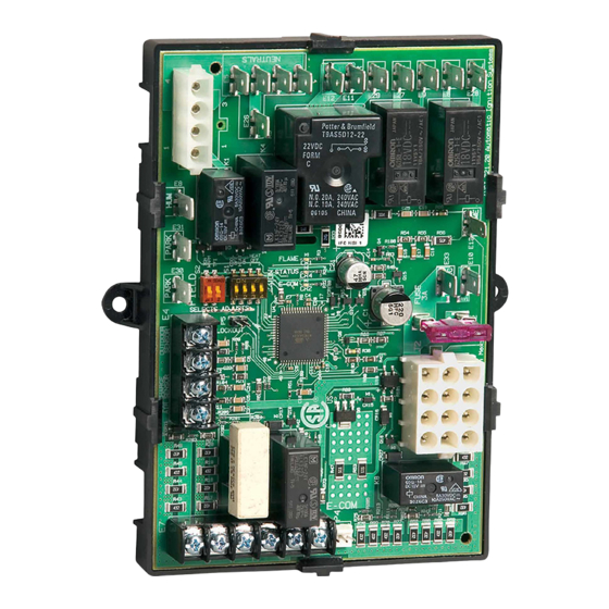
S9200U1000 Universal Hot Surface
Ignition Integrated Furnace Control
APPLICATION
The S9200U1000 Universal Integrated Furnace Control
is a combustion control used in single stage gas heating
and cooling appliances. Keyed wire harnesses allow the
S9200U1000 to replace most furnace controls and to be
applied to most heating and cooling single stage
appliances.
The S9200U1000 can be used with conventional
thermostats as well as the EnviraCOM™ enabled
VisionPRO IAQ and FocusPRO. The S9200U1000
Universal Integrated Furnace Control is intended for
residential natural or liquid propane fueled furnaces only.
The S9200U1000 EnvriaCOM™ communications
capability allows its use in twinning applications and
enables communication with local and remote diagnostic
devices such as the QuickLook hand held device
(QuickLook™ 72), EnviraLNK® web-based application
and the W8735D Telephone Access Module (TAM).
The S9200U1000 provides:
• Main burner ignition using a 120V hot surface
igniter.
• Flame rectification circuit to monitor flame
presence.
• Monitoring of system pressure switch, high
temperature limit, and rollout functions.
• Appliance operation/safety requirements
controlled via microprocessor.
• Control of a standard induction-type circulating
fan motor (based on appliance requirements), in
response to a conventional low voltage or
EnviraCOM™ thermostat.
• LED system status, performance and diagnostic
indication.
• Wire harnesses provided for simple replacement
of most IFCs and integration with most heating
and cooling appliances.
• Twinning capability
• EnviraCOM™ communication capability to enable
local and/or remote system status, diagnostics,
troubleshooting, and HVAC system control.
INSTALLATION INSTRUCTIONS
SPECIFICATIONS
Line Voltage: Line 120V (97-132 Vac), 60 Hz
Low Voltage: Line 24V (19-30 Vac), 60 Hz
Current Draw: 0.5A Input Current @24 Vac, plus valve
load @ 24 Vac plus cooling contactor
Igniter Current: 5.0A resistive @ 132 Vac output
Thermostat Anticipator Setting: (Stage 1 only) 100mA
Prepurge: 30 seconds
HSI Warmup: 17/27 or 30/30 seconds (1st/next trial)
depending on DIP switch S2 setting
Trial for Ignition: 4, 6, or 8 seconds depending on DIP
switch S2 setting
Postpurge: 15 seconds
Inter-trial Purge: 60 seconds
Auto Restart Delay: 60 minutes (after Soft Lockout)
Ignition Trials: Three; two retries if flame is not sensed
on the first trial
Flame Failure Response Time: 2 seconds maximum @
1μA
LEDs: Three LEDs provide the following:
• A red LED provides system status and faults
• An amber LED provides flame status information
• A green LED provides information about the
EnviraCOM™ traffic
Wire harnesses:
• 12 pin, 3 x 4 connector, 7 inches; main harness
• 4-pin (4 x 1) connector, 7 inches; igniter/inducer
harness
Fan Delays:
Heat Fan ON Delay: 30 or 60 seconds depending on
DIP switch S1 setting
Heat Fan OFF Delay: 60, 90, 120, or 180 seconds
depending on Dip Switch S1 setting
Cool Fan ON Delay: 5 seconds
Cool Fan OFF Delay: 0 or 60 seconds (depending on
DIP Switch S1 setting)
Gas Control: Any 24 Vac redundant, direct ignition gas
control rated at 1.5A or less; Honeywell
VR88345M4320 recommended
Cooling Contactor:
Any 24 Vac contactor rated at 1.0A or less
Induced Draft Blower:
2.2FLA/3.5LRA maximum @ 120 Vac
Circulator Load: 14.5FLA/25LRA maximum @ 120 Vac
Line Voltage Humidifier:
1A resistive load maximum @ 120 Vac
Electronic Air Cleaner:
1A resistive load maximum @ 120 Vac
Replaceable Fuse: 3.0 Amp, Automotive type
Operating Temperature: -40°F to 175°F (-40°C to 79°C)
Relative humidity: 0% to 95% non-condensing
Dimensions: See Fig. 1 on page 7
69-2075-01
Advertisement
Table of Contents

Related Manuals for Honeywell S9200U1000


Summary of Contents for Honeywell S9200U1000
- Page 1 Keyed wire harnesses allow the Current Draw: 0.5A Input Current @24 Vac, plus valve S9200U1000 to replace most furnace controls and to be load @ 24 Vac plus cooling contactor applied to most heating and cooling single stage Igniter Current: 5.0A resistive @ 132 Vac output...
-
Page 2: Cross Reference
S9200U1000 UNIVERSAL HOT SURFACE IGNITION INTEGRATED FURNACE CONTROL INSTALLATION AND 3. Mount the S9200U100 Integrated Furnace Control. See “Replacement” on page 6. CONFIGURATION STEPS - 4. Connect the wiring harnesses and make the wiring connections. See “Wiring” on page 7. - Page 3 S9200U1000 UNIVERSAL HOT SURFACE IGNITION INTEGRATED FURNACE CONTROL Table 1. S9200U1000 Replaces These Integrated Furnace Controls. (Continued) Field Settings Recommendation - Safety Timing Settings - Harness DIP Switch S1 (See Table 8) DIP Switch S2 (See Table 9) Texas Instruments...
- Page 4 S9200U1000 UNIVERSAL HOT SURFACE IGNITION INTEGRATED FURNACE CONTROL Table 1. S9200U1000 Replaces These Integrated Furnace Controls. (Continued) Field Settings Recommendation - Safety Timing Settings - Harness DIP Switch S1 (See Table 8) DIP Switch S2 (See Table 9) Lennox 50024561...
- Page 5 S9200U1000 UNIVERSAL HOT SURFACE IGNITION INTEGRATED FURNACE CONTROL Table 1. S9200U1000 Replaces These Integrated Furnace Controls. (Continued) Field Settings Recommendation - Safety Timing Settings - Harness DIP Switch S1 (See Table 8) DIP Switch S2 (See Table 9) Carrier 50026393...
-
Page 6: Installation
1. The integrated furnace control can malfunction or the plugs. We recommend mounting the if it gets wet, leading to accumulation of S9200U1000 in the same location as the old fur- explosive gas. nace control, if possible. Ambient temperature at —... - Page 7 2) and review the appliance wiring 24 Vac Common schematic. High Limit In + Pressure Switch Out The S9200U1000 is intended to connect to the appliance Chassis Ground with the aid of wiring harnesses. Carefully review the wiring harness selection table for the correct wiring Main Valve Common harnesses.
-
Page 8: Wiring Connections
S9200U1000 UNIVERSAL HOT SURFACE IGNITION INTEGRATED FURNACE CONTROL IGNITER/INDUCER HARNESS PLUG CONNECTIONS Table 5. Wiring Connections (Class 1, Line Voltage). The following describes the harness plug connectors for the igniter/inducer. See Table 3 and Fig. 3. Connection Terminal Type (see Fig. 4) - Page 9 S9200U1000 UNIVERSAL HOT SURFACE IGNITION INTEGRATED FURNACE CONTROL MOUNTING HOLE (X2) BOARD CLIPS (X6) PARK PARK E-COM XFMR CONT HEAT FUSE 24 VAC FLAME COOL PLASTIC MOUNTING TRAY M24908 Fig. 4. Typical mounting orientation showing wiring connections to S9200U1000 Universal Integrated Furnace Control. 69-2075—01...
- Page 10 MAIN VALVE SEE TABLE 3 AND FIGURE 3 FOR MAIN HARNESS PLUG CONNECTIONS. 24 VAC HOT SEE TABLE 4 AND FIGURE 4 FOR IGNITER/INDUCER HARNESS CONNECTIONS. 24 VAC COMMON M24916 Fig. 5. Typical wiring connections for S9200U1000 Universal Integrated Furnace Control.
-
Page 11: Safety Timings, Field Settings, And Fixed Parameters
S9200U1000 UNIVERSAL HOT SURFACE IGNITION INTEGRATED FURNACE CONTROL SAFETY TIMINGS, FIELD SETTINGS, Table 7. Fixed Parameters. AND FIXED PARAMETERS Fixed Parameter Setting Pre-Purge 30 seconds WARNING Inter-trial Purge 60 seconds Postpurge 15 seconds Fire or Explosion Hazard. Cool Fan ON Delay... -
Page 12: Thermostat Type
EnviraCOM™ Bus, each S9200U1000 control proceeds SW4 on DIP switch S1 according to Table 8 on page 11. into Twinning Mode. If one of two S9200U1000 controls is removed from a Twinning application, the remaining DIP Switch S2 - Safety Timings control reverts back to standard operation only after power to the control is cycled. -
Page 13: Check Conventional 24 Vac Thermostat
S9200U1000 is in run mode continuously for one Upon a call for heat: hour. — The S9200U1000 conducts a safe start check that consists of an internal hardware/software self- Rollout Circuit Operation (during Heat cycle) check and verification there is no main burner flame present. -
Page 14: Normal Cooling Mode
Normal Cooling Mode recycle). A call for cooling is signaled by: The S9200U1000 remains in this state until the limit circuit — The shorting of R/2 to Y. closes. Once the limit circuit closes: — The shorting of R/2 to Y and G simultaneously. -
Page 15: Error Conditions
— All outputs are turned off except for the inducer, which is kept energized. If the S9200U1000 is servicing a call for heat and flame is — The circulator energizes at the heat speed. sensed when it is not expected to be present, the ignition —... - Page 16 — If either the secondary to chassis connection, or page 22. the chassis to earth ground connection are miss- The S9200U1000 is reset from Soft Lockout by any one of ing or providing poor electrical contact, the the following three ways: S9200U1000 proceeds to Self Check Lockout —...
-
Page 17: Operating Sequences
HEAT FAN OFF DELAY DE-ENERGIZED POST PURGE PERIOD (HEAT SPEED) SOFT LOCKOUT AUTOMATICALLY RESETS AFTER ONE (1) HOUR. 2 HARD LOCKOUT REQUIRES CYCLING OF POWER TO RESET THE LOCKOUT. M24911 Fig. 9. S9200U1000 sequence - Call for Heat cycle. 69-2075—01... - Page 18 S9200U1000 UNIVERSAL HOT SURFACE IGNITION INTEGRATED FURNACE CONTROL 2. CALL FOR COOLING 3. CALL FOR FAN COOLING REQUEST CALL FOR FAN RECEIVED WAIT FOR COMPRESSOR SHORT CYCLE CIRCULATOR ON DELAY TO EXPIRE (HEAT SPEED) ENERGIZE COOLING CONTACTOR (COMPRESSOR) REQUEST MAINTAIN...
-
Page 19: Troubleshooting
S9200U1000 UNIVERSAL HOT SURFACE IGNITION INTEGRATED FURNACE CONTROL TROUBLESHOOTING LED Indicators The S9200U1000 has three LEDs. The three LEDs from left to right as shown in Fig. 4 on page 9 are: WARNING • Flame – Amber LED Fire, Explosion, or Electrical Shock Hazard. - Page 20 S9200U1000 UNIVERSAL HOT SURFACE IGNITION INTEGRATED FURNACE CONTROL Table 11. Control Status Codes (Red LED). Flash Red LED Status Code and Error Code Description Check / Repair Pulse Control powered (Standby; No Call for Not Applicable Heat) Heartbeat Call for Heat - Normal operation...
- Page 21 - Pulse: A 0.25 second flash followed by 3.75 seconds of off time. - Heartbeat: Constant 0.5 second bright, 0.5 second dim cycles. - During start-up the STATUS LED blinks fast for approximately 2 seconds. If the S9200U1000 continues blinking fast (8 pulses/second), the control has failed and must be replaced.
-
Page 22: Status Codes History
Status Codes History Clearing the Status Code History This procedure erases the entire history of fault (error) The S9200U1000 stores the ten (10) most recent error codes. codes. These codes can be recalled for viewing during troubleshooting and cleared if necessary... -
Page 23: Test Mode
Flame current caution level while running Display/Diagnostics Test Mode The S9200U1000 is equipped with a Test Mode feature Test Mode can be accessed several ways: which allows the control to test and verify several critical — Thermostat inputs: parameters. - Page 24 S9200U1000 UNIVERSAL HOT SURFACE IGNITION INTEGRATED FURNACE CONTROL QuickLook™ 72 is a trademark of OnWatch Electronics Inc. EnviraCom™ is a trademark of Honeywell. EnviraLNK® is a registered trademark of Honeywell. Automation and Control Solutions Honeywell International Inc. Honeywell Limited-Honeywell Limitée...