Table of Contents
Advertisement
Quick Links
FX
SERIES PROGRAMMABLE CONTROLLERS
3U
USER'S MANUAL
Hardware Edition
Main Unit
AC Power Type
FX
- MR/ES
3U
FX
- MT/ES
3U
FX
- MT/ESS
3U
FX
- MS/ES
3U
FX
- MR/UA1
3U
DC Power Type
FX
- MR/DS
3U
FX
- MT/DS
3U
FX
- MT/DSS
3U
Input/Output Powered
Extension Unit
FX
- E -
2N
Input/Output Extension Block
FX
-8E -
2N
FX
-16E -
2N
Special Adapter
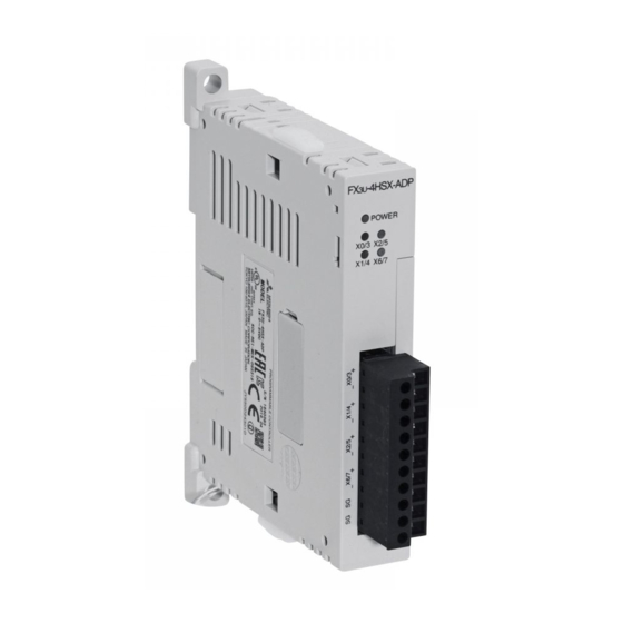
FX
-4HSX-ADP
3U
Display Module
FX
-7DM
3U
Memory Cassette
FX
-FLROM-
3U
Advertisement
Table of Contents
Troubleshooting

Related Manuals for Mitsubishi FX3U-?*MR/ES


Summary of Contents for Mitsubishi FX3U-?*MR/ES
- Page 1 SERIES PROGRAMMABLE CONTROLLERS USER'S MANUAL Hardware Edition Main Unit AC Power Type - MR/ES - MT/ES - MT/ESS - MS/ES - MR/UA1 DC Power Type - MR/DS - MT/DS - MT/DSS Input/Output Powered Extension Unit - E - Input/Output Extension Block -8E - -16E - Special Adapter...
- Page 3 Safety Precautions (Read these precautions before use.) Before installation, operation, maintenance or inspection of this product, thoroughly read through and understand this manual and all of the associated manuals. Also, take care to handle the module properly and safely. This manual classifies the safety precautions into two categories: Indicates that incorrect handling may cause hazardous conditions, resulting in death or severe injury.
- Page 4 Safety Precautions (Read these precautions before use.) 2. INSTALLATION PRECAUTIONS Reference • Make sure to cut off all phases of the power supply externally before attempting installation or wiring work. Failure to do so may cause electric shock or damage to the product. Reference •...
- Page 5 Safety Precautions (Read these precautions before use.) 3. WIRING PRECAUTIONS Reference • Make sure to cut off all phases of the power supply externally before attempting installation or wiring work. Failure to do so may cause electric shock or damage to the product. •...
- Page 6 • Do not disassemble or modify the PLC. Doing so may cause fire, equipment failures, or malfunctions. For repair, contact your local Mitsubishi Electric representative. • Turn off the power to the PLC before connecting or disconnecting any extension cable.
- Page 7 Safety Precautions (Read these precautions before use.) 6. TRANSPORTATION AND STORAGE PRECAUTIONS Reference • Before transporting the PLC, turn on the power to the PLC to check that the BATT LED is off. If the PLC is transported with the BATT LED on or the battery exhausted, the battery-backed data may be unstable during transportation.
- Page 8 Safety Precautions (Read these precautions before use.) MEMO...
-
Page 9: Safety Precautions
This manual confers no industrial property rights or any rights of any other kind, nor does it confer any patent licenses. Mitsubishi Electric Corporation cannot be held responsible for any problems involving industrial property rights which may occur as a result of using the contents noted in this manual. - Page 10 • Since the examples indicated by this manual, technical bulletin, catalog, etc. are used as a reference, please use it after confirming the function and safety of the equipment and system. Mitsubishi Electric will accept no responsibility for actual use of the product based on these illustrative examples.
-
Page 11: Table Of Contents
Series Programmable Controllers User's Manual - Hardware Edition Table of Contents Table of Contents SAFETY PRECAUTIONS ....................(1) Standards Certification of UL, cUL standards ..................... 15 Compliance with EC directive (CE Marking) ..................16 Requirement for Compliance with EMC directive .................. 16 Requirement for Compliance with LVD directive ................... - Page 12 Series Programmable Controllers User's Manual - Hardware Edition Table of Contents 4.3 Input Specifications ........................56 4.3.1 24V DC input (sink/source) type....................56 4.3.2 100V AC input type........................57 4.4 Output Specifications ........................58 4.4.1 Relay output type........................... 58 4.4.2 Product life of relay contacts ......................59 4.4.3 Transistor output (sink) type ......................
- Page 13 Series Programmable Controllers User's Manual - Hardware Edition Table of Contents 6.5 Expansion of Main Unit (Calculation of Current Consumption)............. 98 6.5.1 Quick reference matrix - when only input/output devices are added (AC Power Supply/DC Input Type) ................... 98 6.5.2 When special extension devices are also added [calculation of current consumption] (AC Power Supply/DC Input Type) ..................
- Page 14 Series Programmable Controllers User's Manual - Hardware Edition Table of Contents 8.6 Procedures for Installing Directly (with M4 Screws)..............155 8.6.1 Hole pitches for direct mounting ....................155 8.6.2 Example of mounting hole pitches....................158 8.6.3 Installation of main unit........................ 159 8.6.4 Installation of input/output powered extension unit/block and special function unit/block ...
- Page 15 Series Programmable Controllers User's Manual - Hardware Edition Table of Contents 10.5 Pulse Catch (M8170 to M8177) ....................204 10.5.1 Allocation of special memories to input numbers (ON duration of input signals) ...... 204 10.5.2 Cautions for pulse catch ......................204 10.5.3 Examples of external wiring.......................
- Page 16 Series Programmable Controllers User's Manual - Hardware Edition Table of Contents 13. Examples of Wiring for Various Uses 13.1 Notes about Examples of Wiring....................250 13.2 Digital Switch [DSW Instruction (FNC 72)/BIN Instruction (FNC 19)] ........251 13.2.1 When DSW instructions are used....................251 13.2.2 When BIN instructions are used ....................
- Page 17 Series Programmable Controllers User's Manual - Hardware Edition Table of Contents 15.5 FX -32ER, FX -48ER, FX -48ER-D................. 303 15.5.1 Product specifications........................ 303 15.5.2 External dimensions ........................304 15.5.3 Terminal layout .......................... 305 15.6 FX -32ET, FX -48ET, FX -48ET-D................... 306 15.6.1 Product specifications........................
- Page 18 Series Programmable Controllers User's Manual - Hardware Edition Table of Contents 16.11 FX -8EYT, FX -16EYT and FX -16EYT-C (Transistor Output) ........346 16.11.1 Product specifications......................346 16.11.2 Parts identification and terminal arrangement ................. 347 16.11.3 External dimensions ........................ 348 16.12 FX -8EYT-H (Transistor Output) ..................
- Page 19 Series Programmable Controllers User's Manual - Hardware Edition Table of Contents 18.3 Special Adapters ........................371 18.3.1 FX -4AD-ADP ......................... 371 18.3.2 FX -4DA-ADP ......................... 372 18.3.3 FX -3A-ADP..........................372 18.3.4 FX -4AD-PT(W)-ADP ......................372 18.3.5 FX -4AD-PNK-ADP ........................ 373 18.3.6 FX -4AD-TC-ADP ........................
- Page 20 Series Programmable Controllers User's Manual - Hardware Edition Table of Contents 19.13 Keyword (Entry code)......................404 19.13.1 Keyword (Entry code) types & levels..................404 19.13.2 Level-specific restrictions screen list ..................405 19.13.3 Keyword (Entry code) storage ....................406 19.13.4 Screens requiring keywords (entry codes) for access............. 406 19.13.5 Canceling an keyword (entry code) ..................
- Page 21 Series Programmable Controllers User's Manual - Hardware Edition Table of Contents 20.4 Installation Work........................446 20.4.1 Mounting............................ 446 20.4.2 Removal ............................ 446 20.4.3 Input/output cable connection....................446 20.4.4 Connection to terminal block ..................... 447 20.5 FX-16E-TB, FX-32E-TB ......................448 20.5.1 Internal circuit ..........................448 20.5.2 Example of input external wiring....................
- Page 22 Series Programmable Controllers User's Manual - Hardware Edition Table of Contents 22.4 Battery-Free Operation ......................471 22.5 Battery Replacement......................... 472 22.6 Battery Related Precautions ..................... 472 Appendix A: Operation of Special Devices (M8000 -, D8000 -) Appendix A-1 Special Auxiliary Relay (M8000 to M8511) ............473 Appendix A-2 Special Data Register (D8000 to D8511) ............
-
Page 23: Standards
Series Programmable Controllers Standards User's Manual - Hardware Edition Standards Certification of UL, cUL standards series main units, FX series special adapters and FX input/output extension units/blocks supporting UL, cUL standards are as follows: UL, cUL file number :E95239 Models : MELSEC FX series manufactured MR/ES... -
Page 24: Compliance With Ec Directive (Ce Marking)
Compliance to EMC directive and LVD directive of the entire mechanical module should be checked by the user / manufacturer. For more details please contact to the local Mitsubishi Electric sales site. Requirement for Compliance with EMC directive... - Page 25 Series Programmable Controllers Standards User's Manual - Hardware Edition Type : Programmable Controller (Open Type Equipment) Models : MELSEC FX series manufactured from May 1st, 2005 MR/ES Where indicates:16,32,48,64,80 -4HSX-ADP -2HSY-ADP -FLROM-16 -FLROM-64L -7DM from June 1st, 2005 -232ADP -485ADP -4AD-ADP -4DA-ADP -4AD-PT-ADP FX...
- Page 26 Series Programmable Controllers Standards User's Manual - Hardware Edition Models : MELSEC FX series manufactured from July 1st, 1997 ER-ES/UL ET-ESS/UL Where indicates:32,48 -16EX-ES/UL -16EYR-ES/UL -16EYT-ESS/UL from April 1st, 1998 -48ER-DS -48ET-DSS from August 1st, 1998 -48ER-UA1/UL from August 1st, 2005 -8ER-ES/UL -8EX-ES/UL -8EYR-ES/UL...
-
Page 27: Requirement For Compliance With Lvd Directive
Series Programmable Controllers Standards User's Manual - Hardware Edition Requirement for Compliance with LVD directive The following products have shown compliance through direct testing (of the identified standards below) and design analysis (through the creation of a technical construction file) to the European Directive for Low Voltage (2006/95/EC) when used as directed by the appropriate documentation. -
Page 28: Caution For Compliance With Ec Directive
(integral with sensors or actuators), these users should follow those manufacturers' installation requirements. Mitsubishi Electric recommends that shielded cables be used. If NO other EMC protection is provided, users may experience temporary induced errors not exceeding +10%/-10% in very heavy industrial areas. -
Page 29: Introduction
Series Programmable Controllers 1 Introduction User's Manual - Hardware Edition 1.1 Introduction of Manuals Introduction This manual explains the procedures for selecting the system components, main unit specifications and procedures for installing the main unit, specifications for the input/output powered extension units/blocks, and procedures for adding input/output devices, and procedures for operating the display module etc. - Page 30 Series Programmable Controllers 1 Introduction User's Manual - Hardware Edition 1.1 Introduction of Manuals 2. Extension devices (Chapter 15 to 18) Division Outline Reference Input/output powered extension This chapter contains explanations for the input/output Chapter 15 units specifications, external dimensions and terminal layout for each product.
-
Page 31: Manual Organization And Position Of This Manual
Series Programmable Controllers 1 Introduction User's Manual - Hardware Edition 1.1 Introduction of Manuals 1.1.2 Manual organization and position of this manual This manual describes detail on the hardware, including the system configuration, selection, installation and wiring. The instructions, communication control, analog control and positioning control are explained in separate manuals. -
Page 32: List Of Manuals
Series Programmable Controllers 1 Introduction User's Manual - Hardware Edition 1.1 Introduction of Manuals 1.1.3 List of manuals Series PLC main units supplied only with the hardware manual. For details on the hardware of FX Series, refer to this manual. For instructions for programming and hardware information on special function devices, refer to the relevant manuals. - Page 33 Series Programmable Controllers 1 Introduction User's Manual - Hardware Edition 1.1 Introduction of Manuals : Indispensable manuals : Manuals necessary for some purposes : Manuals with separate volumes for details Manual Model Manual title Contents number name code RS-232C/RS-422/RS-485/USB communication When using each product, also refer to the User's Manual - Hardware Edition for the PLC main unit to be installed.
- Page 34 Series Programmable Controllers 1 Introduction User's Manual - Hardware Edition 1.1 Introduction of Manuals : Indispensable manuals : Manuals necessary for some purposes : Manuals with separate volumes for details Manual Model Manual title Contents number name code CC-Link, CC-Link/LT, MELSEC I/O LINK, and AS-i system When using each product, also refer to the User's Manual - Hardware Edition for the PLC main unit to be installed.
- Page 35 Series Programmable Controllers 1 Introduction User's Manual - Hardware Edition 1.1 Introduction of Manuals : Indispensable manuals : Manuals necessary for some purposes : Manuals with separate volumes for details Manual Model Manual title Contents number name code Handling procedures for the 4-ch analog Supplied input special function block -4AD...
- Page 36 Series Programmable Controllers 1 Introduction User's Manual - Hardware Edition 1.1 Introduction of Manuals : Indispensable manuals : Manuals necessary for some purposes : Manuals with separate volumes for details Manual Model Manual title Contents number name code Analog output When using each product, also refer to the User's Manual - Hardware Edition for the PLC main unit to be installed.
- Page 37 Series Programmable Controllers 1 Introduction User's Manual - Hardware Edition 1.1 Introduction of Manuals : Indispensable manuals : Manuals necessary for some purposes : Manuals with separate volumes for details Manual Model Manual title Contents number name code Pulse output and positioning When using each product, also refer to the User's Manual - Hardware Edition for the PLC main unit to be installed.
- Page 38 Series Programmable Controllers 1 Introduction User's Manual - Hardware Edition 1.1 Introduction of Manuals : Indispensable manuals : Manuals necessary for some purposes : Manuals with separate volumes for details Manual Model Manual title Contents number name code Manuals for FX Describes FX-30P specification extracted Supplied from the FX-30P Operation manual.
-
Page 39: Generic Names And Abbreviations Used In Manuals
Series Programmable Controllers 1 Introduction User's Manual - Hardware Edition 1.2 Generic Names and Abbreviations Used in Manuals Generic Names and Abbreviations Used in Manuals Abbreviation/ Description generic name PLCs Series Generic name for FX Series PLCs Series Generic name for FX Series PLCs Series Generic name for FX... - Page 40 Series Programmable Controllers 1 Introduction User's Manual - Hardware Edition 1.2 Generic Names and Abbreviations Used in Manuals Abbreviation/ Description generic name Series special Generic name for the following models function units -10GM, FX -20GM, FX -1RM(-E)-SET Generic name for the following models -232IF, FX -16CCL-M, FX -32CCL, FX...
- Page 41 Series Programmable Controllers 1 Introduction User's Manual - Hardware Edition 1.2 Generic Names and Abbreviations Used in Manuals Abbreviation/ Description generic name Manuals Hardware Edition Abbreviation of FX Series User's Manual - Hardware Edition Abbreviation of FX Series Programming Manual - Basic & Applied Programming manual Instruction Edition Data Communication...
-
Page 42: Features And Part Names
Series Programmable Controllers 2 Features and Part Names User's Manual - Hardware Edition 2.1 Major Features Features and Part Names Major Features 1. Basic functions sequence. In this case, use instructions and devices within the ranges common to FX [Up to 384 input/output points] Series and the selected model of PLC. - Page 43 Series Programmable Controllers 2 Features and Part Names User’s Manual - Hardware Edition 2.1 Major Features [Input interruption function (with delay function)] [Other functions] Interruption routines processed On the display module, you can set the time, adjust the contrast and display the PLC version preferentially by external signals with the minimum ON or OFF width of 5 µs (X000 to X005).
-
Page 44: Names And Functions Of Parts
Series Programmable Controllers 2 Features and Part Names User's Manual - Hardware Edition 2.2 Names and Functions of Parts Names and Functions of Parts 2.2.1 Front Panel Factory default configuration (standard) [1] Top cover [9] Input display LEDs [2] Battery cover [10] Terminal block covers [3] Special adapter connecting hooks... - Page 45 Series Programmable Controllers 2 Features and Part Names User’s Manual - Hardware Edition 2.2 Names and Functions of Parts [12] Operation status display LEDs The operation status of the PLC can be checked with the LEDs. The LEDs turn off, light and flash according to the following table. →...
-
Page 46: Sides
Series Programmable Controllers 2 Features and Part Names User's Manual - Hardware Edition 2.2 Names and Functions of Parts 2.2.2 Sides [1] Cover of special adapter Right side Left side connector [2] Cover of high-speed input/output special adapter connector [3] Expansion board securing screw holes [4] Nameplate [5] DIN rail mounting groove... -
Page 47: Introduction Of Products (Compliant With Overseas Standards)
Series Programmable Controllers 3 Introduction of Products (Compliant with Overseas Standards) User’s Manual - Hardware Edition 3.1 List of Products (to be Connected) and Interpretation of Model Names Introduction of Products (Compliant with Overseas Standards) List of Products (to be Connected) and Interpretation of Model Names The following system configuration is classified into product groups A to O in the product introduction sections given below. -
Page 48: A] Main Units
Relay -80MT/DS Transistor (sink) -80MT/DSS Transistor (source) * Please consult with Mitsubishi Electric for information on marine standard practices and the corresponding types of equipment. → For more information on CE, UL and cUL, refer to Page 15 or later. -
Page 49: B] Input/Output Powered Extension Units
-32MR/UA1 Relay -64MR/UA1 Relay Please consult with Mitsubishi Electric for information on marine standard practices and the corresponding types of equipment. → For more information on CE, UL and cUL, refer to Page 15 or later. 3.1.2 [B] Input/output powered extension units The input/output powered extension unit incorporates a power supply circuit and input and output terminals. -
Page 50: C] Input/Output Extension Blocks
Terminal block Four inputs and four outputs are occupied as unused numbers. Please consult with Mitsubishi Electric for information on marine standard practices and the corresponding types of equipment. → For more information on CE, UL and cUL, refer to Page 15 or later. -
Page 51: D] [E] Special Function Units/Blocks
2 loops thermometer sensor/ thermocouple) * Please consult with Mitsubishi Electric for information on marine standard practices and the corresponding types of equipment. → For more information on CE, UL and cUL, refer to Page 15 or later. 2. High-speed counter : Not targeted −... - Page 52 − − -32ASI-M Master for AS-i system * Please consult with Mitsubishi Electric for information on marine standard practices and the corresponding types of equipment. → For more information on CE, UL and cUL, refer to Page 15 or later.
-
Page 53: F] Display Modules And Holder
(manual in English supplied) Products manufactured in and after May, 2005 will comply with the overseas standard. Please consult with Mitsubishi Electric for information on marine standard practices and the corresponding types of equipment. → For more information on CE, UL and cUL, refer to Page 15 or later. -
Page 54: H] Special Adapters
4-ch thermocouple (K, J type) temperature sensor input Products manufactured in and after June, 2005 will comply with the overseas standard. Please consult with Mitsubishi Electric for information on marine standard practices and the corresponding types of equipment. → For more information on CE, UL and cUL, refer to Page 15 or later. -
Page 55: I] Extension Power Supply Unit
-2HSY-ADP For differential line driver output (for positioning output) * Please consult with Mitsubishi Electric for information on marine standard practices and the corresponding types of equipment. → For more information on CE, UL and cUL, refer to Page 15 or later. -
Page 56: M] Fx Series Terminal Blocks (Cables And Connectors)
Series Programmable Controllers 3 Introduction of Products (Compliant with Overseas Standards) User’s Manual - Hardware Edition 3.1 List of Products (to be Connected) and Interpretation of Model Names 3.1.10 [M] FX Series terminal blocks (cables and connectors) 1. FX Series terminal blocks : Not targeted −... -
Page 57: Connector Types And Cables For Program Communication
Series Programmable Controllers 3 Introduction of Products (Compliant with Overseas Standards) User’s Manual - Hardware Edition 3.2 Connector Types and Cables for Program Communication Connector Types and Cables for Program Communication Peripheral device connector FX-232AWC-H RS-232C RS-422 FX-USB-AW FX-30P FX-20P-CAB0 Special adapter -232ADP(-MB) FX -2 32A D P... -
Page 58: Programming Tool
Series Programmable Controllers 3 Introduction of Products (Compliant with Overseas Standards) User’s Manual - Hardware Edition 3.2 Connector Types and Cables for Program Communication 3.2.1 Programming tool The following programming tool supports FX Series PLCs. Model name Description Version 1.07H or later of SW DNC-GXW2-J supports the FX GX Works2 Version 1.08J or later of SW DNC-GXW2-E supports the FX Version 8.23Z or later of SW D5C-GPPW-J supports the FX... -
Page 59: Converters And Interface
Series Programmable Controllers 3 Introduction of Products (Compliant with Overseas Standards) User’s Manual - Hardware Edition 3.2 Connector Types and Cables for Program Communication 3.2.3 Converters and interface : Not targeted − : Not applicable : Compliance with standard or self-declaration Model name Description Marine... -
Page 60: Specifications, External Dimensions And Terminal Layout (Main Units)
Series Programmable Controllers 4 Specifications, External Dimensions and Terminal Layout (Main Units) User’s Manual - Hardware Edition 4.1 Generic Specifications Specifications, External Dimensions and Terminal Layout (Main Units) This Chapter explains the specifications, external dimensions and terminal layout of the main units. →... -
Page 61: Dielectric Withstand Voltage Test And Insulation Resistance Test
Series Programmable Controllers 4 Specifications, External Dimensions and Terminal Layout (Main Units) User’s Manual - Hardware Edition 4.1 Generic Specifications 4.1.1 Dielectric withstand voltage test and insulation resistance test Perform dielectric withstand voltage test and insulation resistance test at the following voltage between each terminals and the main unit ground terminal. -
Page 62: Power Supply Specifications
Series Programmable Controllers 4 Specifications, External Dimensions and Terminal Layout (Main Units) User’s Manual - Hardware Edition 4.2 Power Supply Specifications Power Supply Specifications The specifications for the main unit power supply are explained below. For the power (current) consumed by the special function units/blocks, refer to this manual or the special function units/blocks manual. -
Page 63: Dc Power Supply/Dc Input Type
Series Programmable Controllers 4 Specifications, External Dimensions and Terminal Layout (Main Units) User’s Manual - Hardware Edition 4.2 Power Supply Specifications 4.2.2 DC Power Supply/DC Input Type Specifications Item -16M /D -32M /D -48M /D -64M /D -80M /D 24V DC Supply voltage Allowable supply 16.8 to 28.8V DC... -
Page 64: Input Specifications
Series Programmable Controllers 4 Specifications, External Dimensions and Terminal Layout (Main Units) User’s Manual - Hardware Edition 4.3 Input Specifications Input Specifications The main unit input specifications are explained below. 4.3.1 24V DC input (sink/source) type The input numbers in the table indicate the main unit terminal numbers. "X010 or more" means the numbers from X010 to the largest number that the main unit has. -
Page 65: Ac Input Type
Series Programmable Controllers 4 Specifications, External Dimensions and Terminal Layout (Main Units) User’s Manual - Hardware Edition 4.3 Input Specifications 4.3.2 100V AC input type → For handling of 100V AC input, refer to Subsection 10.3.2. Specifications Item -32MR/UA1 -64MR/UA1 Input points 16 points 32 points... -
Page 66: Output Specifications
Series Programmable Controllers 4 Specifications, External Dimensions and Terminal Layout (Main Units) User’s Manual - Hardware Edition 4.4 Output Specifications Output Specifications The main unit output specifications are explained below. 4.4.1 Relay output type The output numbers in the table indicate the main unit terminal numbers. "Y010 or more" means the numbers from Y010 to the largest number that the main unit has. -
Page 67: Product Life Of Relay Contacts
Series Programmable Controllers 4 Specifications, External Dimensions and Terminal Layout (Main Units) User’s Manual - Hardware Edition 4.4 Output Specifications 4.4.2 Product life of relay contacts The product life of relay contacts varies considerably depending on the load type used. Take care that loads generating reverse electromotive force or rush current may cause poor contact or deposition of contacts which may lead to considerable reduction of the contact product life. -
Page 68: Transistor Output (Sink) Type
Series Programmable Controllers 4 Specifications, External Dimensions and Terminal Layout (Main Units) User’s Manual - Hardware Edition 4.4 Output Specifications 4.4.3 Transistor output (sink) type The output numbers in the table indicate the main unit terminal numbers. "Y010 or more" means the numbers from Y010 to the largest number that the main unit has. -
Page 69: Transistor Output (Source) Type
Series Programmable Controllers 4 Specifications, External Dimensions and Terminal Layout (Main Units) User’s Manual - Hardware Edition 4.4 Output Specifications 4.4.4 Transistor output (source) type The output numbers in the table indicate the main unit terminal numbers. "Y010 or more" means the numbers from Y010 to the largest number that the main unit has. -
Page 70: Triac Output Type
Series Programmable Controllers 4 Specifications, External Dimensions and Terminal Layout (Main Units) User’s Manual - Hardware Edition 4.4 Output Specifications 4.4.5 Triac output type Triac output specifications Item -32MS/ES -64MS/ES 16 points 32 points Number of output points Connecting type Removable terminal block (M3 screw) Output type Triac output (SSR) -
Page 71: Performance Specifications
Series Programmable Controllers 4 Specifications, External Dimensions and Terminal Layout (Main Units) User’s Manual - Hardware Edition 4.5 Performance Specifications Performance Specifications The performance specifications are common to FX Series PLCs. Item Performance Stored program repetitive operation system (dedicated LSI) with Operation control system interruption function Batch processing system (when END instruction is executed) - Page 72 Series Programmable Controllers 4 Specifications, External Dimensions and Terminal Layout (Main Units) User’s Manual - Hardware Edition 4.5 Performance Specifications Item Performance (1)Extension- 248 points combined number (1) + (2) ≤ (3) total number of points is of input points (3) total points 256 or less.
- Page 73 Series Programmable Controllers 4 Specifications, External Dimensions and Terminal Layout (Main Units) User’s Manual - Hardware Edition 4.5 Performance Specifications Item Performance 1-phase 1-count input Counting from -2,147,483,648 to C235 to C245 in both directions (32 Up to 8 +2.147,483,647 [For keeping] bits) [changeable] points can The retentive status can be changed by...
-
Page 74: External Dimensions (Weight And Installation)
Series Programmable Controllers 4 Specifications, External Dimensions and Terminal Layout (Main Units) User’s Manual - Hardware Edition 4.6 External Dimensions (Weight and Installation) External Dimensions (Weight and Installation) The external dimensions of the main unit are explained. 4.6.1 -16M , FX -32M Unit: mm (inches) 2-φ... -
Page 75: Fx 3U -48M , Fx 3U -64M , Fx 3U -80M , Fx 3U -128M
Series Programmable Controllers 4 Specifications, External Dimensions and Terminal Layout (Main Units) User’s Manual - Hardware Edition 4.6 External Dimensions (Weight and Installation) 4.6.2 -48M , FX -64M , FX -80M , FX -128M 4-φ 4.5 mounting holes Unit: mm (inches) 22 (0.87") W1 (mounting hole pitch) 9 (0.36") -
Page 76: Terminal Layout
Series Programmable Controllers 4 Specifications, External Dimensions and Terminal Layout (Main Units) User’s Manual - Hardware Edition 4.7 Terminal Layout Terminal Layout The terminal layout in the main unit is shown below. 4.7.1 Interpretation Interpretation of terminal block layout Power supply 24V DC service [ •... -
Page 77: Fx 3U -16M
Series Programmable Controllers 4 Specifications, External Dimensions and Terminal Layout (Main Units) User’s Manual - Hardware Edition 4.7 Terminal Layout 4.7.2 -16M • AC power supply/DC input type S/S 0V -16MR/ES -16MT/ES -16MT/ESS COM0 COM1 COM2 COM3 COM4 COM5 COM6 COM7 •... -
Page 78: Fx 3U -32M
Series Programmable Controllers 4 Specifications, External Dimensions and Terminal Layout (Main Units) User’s Manual - Hardware Edition 4.7 Terminal Layout 4.7.3 -32M • AC power supply/DC input type S/S 0V -32MR/ES,FX -32MT/ES,FX -32MS/ES COM1 COM2 COM3 COM4 -32MT/ESS • DC power supply/DC input type (0V) (24V) -32MR/DS, FX... -
Page 79: Fx 3U -48M
Series Programmable Controllers 4 Specifications, External Dimensions and Terminal Layout (Main Units) User’s Manual - Hardware Edition 4.7 Terminal Layout 4.7.4 -48M • AC power supply/DC input type S/S 0V -48MR/ES, FX -48MT/ES COM5 COM1 COM2 COM3 COM4 -48MT/ESS • DC power supply/DC input type (0V) (24V) -48MR/DS, FX... -
Page 80: Fx 3U -64M
Series Programmable Controllers 4 Specifications, External Dimensions and Terminal Layout (Main Units) User’s Manual - Hardware Edition 4.7 Terminal Layout 4.7.5 -64M • AC power supply/DC input type S/S 0V -64MR/ES, FX -64MT/ES, FX -64MS/ES COM6 COM1 COM2 COM3 COM4 COM5 -64MT/ESS •... -
Page 81: Fx 3U -80M
Series Programmable Controllers 4 Specifications, External Dimensions and Terminal Layout (Main Units) User’s Manual - Hardware Edition 4.7 Terminal Layout 4.7.6 -80M • AC power supply/DC input type Terminal block 1 Terminal block 2 S/S 0V -80MR/ES, FX3U-80MT/ES COM6 COM7 COM1 COM2 COM3... -
Page 82: Fx 3U -128M
Series Programmable Controllers 4 Specifications, External Dimensions and Terminal Layout (Main Units) User’s Manual - Hardware Edition 4.7 Terminal Layout 4.7.7 -128M • AC power supply/DC input type Terminal block 1 Terminal block 2 S/S 0V -128MR/ES,FX -128MT/ES COM8 COM10 COM9 COM2 COM4... -
Page 83: Version Information And Peripheral Equipment Connectability
Series Programmable Controllers 5 Version Information and Peripheral Equipment Connectability User's Manual - Hardware Edition 5.1 Version Upgrade History Version Information and Peripheral Equipment Connectability Version Upgrade History 5.1.1 How to look at manufacturer’s serial number The year and month of production of the product can be checked on the nameplate, and "LOT" indicated on the front of the product. -
Page 84: Version Check Method
Series Programmable Controllers 5 Version Information and Peripheral Equipment Connectability User's Manual - Hardware Edition 5.1 Version Upgrade History 5.1.2 Version check method In FX PLCs, users can obtain the PLC version information by monitoring special data register D8001 (decimal number), or the PLC version can be checked in "PLC Status" in the display module. →... -
Page 85: Programming Tool Applicability
Series Programmable Controllers 5 Version Information and Peripheral Equipment Connectability User's Manual - Hardware Edition 5.2 Programming Tool Applicability Programming Tool Applicability 5.2.1 Applicable versions of programming tool 1. GX Works2 • GX Works2 Japanese version (SW DNC-GXW2-J) is applicable to FX PLCs from the following versions. -
Page 86: In Case Of Programming Tool (Version) Not Applicable
Series Programmable Controllers 5 Version Information and Peripheral Equipment Connectability User's Manual - Hardware Edition 5.2 Programming Tool Applicability 3. FX-30P FX-30P is applicable to FX PLCs from the following version. Applicable PLC version Model name Remarks FX-30P version Before Ver. 2.41 Ver. -
Page 87: Cautions On Connecting Peripheral Equipment By Way Of Expansion Board Or Special Adapter
Series Programmable Controllers 5 Version Information and Peripheral Equipment Connectability User's Manual - Hardware Edition 5.2 Programming Tool Applicability 5.2.4 Cautions on connecting peripheral equipment by way of expansion board or special adapter When connecting peripheral equipment (programming tool or GOT [CPU direct connection]) by way of the -232-BD, FX -422-BD, FX -USB-BD or FX... -
Page 88: Cautions On Write During Run
Series Programmable Controllers 5 Version Information and Peripheral Equipment Connectability User's Manual - Hardware Edition 5.2 Programming Tool Applicability 5.2.5 Cautions on write during RUN In FX PLCs, write during RUN (program changes in the RUN mode) is enabled using the following programming tools. - Page 89 Series Programmable Controllers 5 Version Information and Peripheral Equipment Connectability User's Manual - Hardware Edition 5.2 Programming Tool Applicability Cautions on write during RUN Item Caution Program memories which can be written in Built-in RAM and optional memory cassette (whose write protect switch is set RUN mode to OFF) •...
- Page 90 Series Programmable Controllers 5 Version Information and Peripheral Equipment Connectability User's Manual - Hardware Edition 5.2 Programming Tool Applicability Item Caution Avoid write during RUN to a circuit block including the following instructions during execution. If write during RUN is executed to such a circuit block, the PLC decelerates and stops pulse output.
- Page 91 Series Programmable Controllers 5 Version Information and Peripheral Equipment Connectability User's Manual - Hardware Edition 5.2 Programming Tool Applicability Item Caution When writing to a circuit block during RUN, which includes the following instructions, the following results. • MEP instruction (Conversion of operation result to leading edge pulse instruction) When completing Write during RUN to a circuit including the MEP instruction, the execution result of the MEP instruction turns ON (conducting...
-
Page 92: Cautions On Using Transparent Function By Way Of Usb In Got1000 Series
Series Programmable Controllers 5 Version Information and Peripheral Equipment Connectability User's Manual - Hardware Edition 5.3 Cautions on using transparent function by way of USB in GOT1000 Series Cautions on using transparent function by way of USB in GOT1000 Series When monitoring circuits, device registration, etc. -
Page 93: Cautions On Using Transparent Port (2-Port) Function Of Got-F900 Series
Series Programmable Controllers 5 Version Information and Peripheral Equipment Connectability User's Manual - Hardware Edition 5.4 Cautions on using transparent port (2-port) function of GOT-F900 Series Cautions on using transparent port (2-port) function of GOT-F900 Series When monitoring circuits, device registration, etc. in an FX PLC from GX Developer Ver. -
Page 94: Other Peripheral Equipment Applicability
Series Programmable Controllers 5 Version Information and Peripheral Equipment Connectability User's Manual - Hardware Edition 5.5 Other Peripheral Equipment Applicability Other Peripheral Equipment Applicability Other Peripheral Equipment Applicability 5.5.1 Model name Applicability Remarks Applicable The GOT1000 Series is applicable to the device ranges in the GOT1000 Series (From first PLCs. -
Page 95: Examination Of System Configuration
Series Programmable Controllers 6 Examination of System Configuration User’s Manual - Hardware Edition 6.1 Configuration of a Whole System Examination of System Configuration Configuration of a Whole System The configuration of a whole system is shown below as an example. Configuration of whole system Expansion board and special adapters Determination of number of extension devices to be connected to main unit... -
Page 96: List Of System Components
Series Programmable Controllers 6 Examination of System Configuration User’s Manual - Hardware Edition 6.1 Configuration of a Whole System 6.1.1 List of system components Other items to be considered Max. Number of Types (extracted) number of Max. number 5V DC 24V DC Classification Reference... - Page 97 Series Programmable Controllers 6 Examination of System Configuration User’s Manual - Hardware Edition 6.1 Configuration of a Whole System For some products, there are restrictions on combination and number of connected units. → For details on the special adapters, refer to Subsection 6.4.1. →...
-
Page 98: System Configuration With Special Adapters
Series Programmable Controllers 6 Examination of System Configuration User’s Manual - Hardware Edition 6.1 Configuration of a Whole System 6.1.2 System configuration with special adapters 1. When high-speed input/output special adapters are used When only high-speed input/output special adapters are connected, the adapters can be used without an expansion board. -
Page 99: Rules Of System Configuration
Series Programmable Controllers 6 Examination of System Configuration User’s Manual - Hardware Edition 6.2 Rules of System Configuration Rules of System Configuration The system configuration must meet the following three requirements. Number of input/output points The total number of input/output points and remote I/O points on CC-Link or AS-i system must be 384 points or less on the whole system. - Page 100 Series Programmable Controllers 6 Examination of System Configuration User’s Manual - Hardware Edition 6.2 Rules of System Configuration Calculation of current consumption The power is supplied to each connected device from the built-in power supply of the main unit, the input/ output powered extension unit or the extension power supply unit.
-
Page 101: Number Of Input/Output Points And Maximum Number Of Input/Output Points
Series Programmable Controllers 6 Examination of System Configuration User’s Manual - Hardware Edition 6.3 Number of Input/Output Points and Maximum Number of Input/Output Points Number of Input/Output Points and Maximum Number of Input/Output Points 6.3.1 Calculation of number of input/output points To obtain the total number of input/output points, count the input/output points of input/output powered extension units/blocks and the input/output occupied points of special function units/blocks. - Page 102 Series Programmable Controllers 6 Examination of System Configuration User’s Manual - Hardware Edition 6.3 Number of Input/Output Points and Maximum Number of Input/Output Points • FX -32ASI-M (AS-i master) Only one FX -32ASI-M unit can be connected to a single PLC main unit. This master cannot be used together with FX -16CCL-M and/or FX -16CCL-M.
-
Page 103: Maximum Number Of Input/Output Points When Cc-Link Master Is Used
Series Programmable Controllers 6 Examination of System Configuration User’s Manual - Hardware Edition 6.3 Number of Input/Output Points and Maximum Number of Input/Output Points 6.3.2 Maximum number of input/output points when CC-Link master is used 1. Calculation of maximum number of input/output points When CC-Link master block is used, the following maximum number of input/output points can be connected. -
Page 104: Maximum Number Of Input/Output Points When As-I Master Is Used
Series Programmable Controllers 6 Examination of System Configuration User’s Manual - Hardware Edition 6.3 Number of Input/Output Points and Maximum Number of Input/Output Points 6.3.3 Maximum number of input/output points when AS-i master is used 1. Calculation of maximum number of input/output points When AS-i system master block is used, the following maximum number of input/output points can be connected. -
Page 105: Number Of Connected Special Extension Devices (Including Extension Cable)
Series Programmable Controllers 6 Examination of System Configuration User’s Manual - Hardware Edition 6.4 Number of Connected Special Extension Devices (Including Extension Cable) Number of Connected Special Extension Devices (Including Extension Cable) 6.4.1 Expansion board and special adapter The number of connected special adapters is restricted depending on the type of special adapters attached as explained below. -
Page 106: Expansion Of Main Unit (Calculation Of Current Consumption)
Series Programmable Controllers 6 Examination of System Configuration User’s Manual - Hardware Edition 6.5 Expansion of Main Unit (Calculation of Current Consumption) Expansion of Main Unit (Calculation of Current Consumption) The amount of connectable extension equipment to the main unit varies, depending on the main unit type. Please select equipment compatible with the main unit used. - Page 107 Series Programmable Controllers 6 Examination of System Configuration User’s Manual - Hardware Edition 6.5 Expansion of Main Unit (Calculation of Current Consumption) Select the input/output extension block (number of points) to be connected to the main unit. Check that the number of input/output points can be added. When connecting the FX -1PSU-5V extension power supply unit to a system where the nearest upstream unit to the FX...
-
Page 108: When Special Extension Devices Are Also Added [Calculation Of Current Consumption] (Ac Power Supply/Dc Input Type)
Series Programmable Controllers 6 Examination of System Configuration User’s Manual - Hardware Edition 6.5 Expansion of Main Unit (Calculation of Current Consumption) 6.5.2 When special extension devices are also added [calculation of current consumption] (AC Power Supply/DC Input Type) Select a main unit. Select a main unit. - Page 109 Series Programmable Controllers 6 Examination of System Configuration User’s Manual - Hardware Edition 6.5 Expansion of Main Unit (Calculation of Current Consumption) Enter the specifications for the products to be added. Enter the data on the input/output extension blocks and special function units/blocks to be connected to the main unit in the following table, and calculate the current.
- Page 110 Series Programmable Controllers 6 Examination of System Configuration User’s Manual - Hardware Edition 6.5 Expansion of Main Unit (Calculation of Current Consumption) Determine whether the devices can be connected to the main unit. Calculate the current to confirm whether the selected extension devices can be connected. 1.
-
Page 111: Quick Reference Matrix [When Only Input/Output Devices Are Added] (Dc Power Type)
Series Programmable Controllers 6 Examination of System Configuration User’s Manual - Hardware Edition 6.5 Expansion of Main Unit (Calculation of Current Consumption) 6.5.3 Quick reference matrix [when only input/output devices are added] (DC Power Type) The following matrix shows the expandable units up to the mark, where the desired inputs (horizontal axis) and outputs (vertical axis) intersect. -
Page 112: When Special Extension Devices Are Also Added [Calculation Of Current Consumption] (Dc Power Type)
Series Programmable Controllers 6 Examination of System Configuration User’s Manual - Hardware Edition 6.5 Expansion of Main Unit (Calculation of Current Consumption) 6.5.4 When special extension devices are also added [calculation of current consumption] (DC Power Type) Select a main unit. Select a main unit. - Page 113 Series Programmable Controllers 6 Examination of System Configuration User’s Manual - Hardware Edition 6.5 Expansion of Main Unit (Calculation of Current Consumption) Enter the specifications for the products to be added. Enter the data on the special function units/blocks to be connected to the main unit in the following table, and calculate the current.
- Page 114 Series Programmable Controllers 6 Examination of System Configuration User’s Manual - Hardware Edition 6.5 Expansion of Main Unit (Calculation of Current Consumption) Determine whether the devices can be connected to the main unit. Calculate the current to confirm whether the selected extension devices can be connected. 1.
-
Page 115: Quick Reference Matrix [When Only Input/Output Devices Are Added] (Ac Power Supply/Ac Input Type)
Series Programmable Controllers 6 Examination of System Configuration User’s Manual - Hardware Edition 6.5 Expansion of Main Unit (Calculation of Current Consumption) 6.5.5 Quick reference matrix [when only input/output devices are added] (AC Power Supply/AC Input Type) The following matrix shows the expandable units up to the mark, where the desired inputs (horizontal axis) and outputs (vertical axis) intersect. -
Page 116: (Ac Power Supply/Ac Input Type)
Series Programmable Controllers 6 Examination of System Configuration User’s Manual - Hardware Edition 6.5 Expansion of Main Unit (Calculation of Current Consumption) 6.5.6 When special extension devices are also added [calculation of current consumption] (AC Power Supply/AC Input Type) Select a main unit. Select a main unit. - Page 117 Series Programmable Controllers 6 Examination of System Configuration User’s Manual - Hardware Edition 6.5 Expansion of Main Unit (Calculation of Current Consumption) Enter the specifications for the products to be added. Enter the data on the special function units/blocks to be connected to the main unit in the following table, and calculate the current.
- Page 118 Series Programmable Controllers 6 Examination of System Configuration User’s Manual - Hardware Edition 6.5 Expansion of Main Unit (Calculation of Current Consumption) Determine whether the devices can be connected to the main unit. Calculate the current to confirm whether the selected extension devices can be connected. 1.
-
Page 119: Expansion Of Fx 2N Series I/O Powered Extension Unit (Calculation Of Current Consumption)
Series Programmable Controllers 6 Examination of System Configuration User’s Manual - Hardware Edition 6.6 Expansion of FX2N Series I/O Powered Extension Unit (Calculation of Current Consumption) Expansion of FX Series I/O Powered Extension Unit (Calculation of Current Consumption) If the selected devices in the previous section cannot be connected due to a shortage of current from the main unit’s built-in 24V DC sercive power supply, add an input/output powered extension unit. - Page 120 Series Programmable Controllers 6 Examination of System Configuration User’s Manual - Hardware Edition 6.6 Expansion of FX2N Series I/O Powered Extension Unit (Calculation of Current Consumption) 2) FX -48ER, FX -48ET -48ER-ES/UL, FX -48ET-ESS/UL Output AC power supply DC input type (Example) 160 110 235 185 135...
- Page 121 Series Programmable Controllers 6 Examination of System Configuration User’s Manual - Hardware Edition 6.6 Expansion of FX2N Series I/O Powered Extension Unit (Calculation of Current Consumption) Check the current capacity of the 24V DC service power supply based on the value shown in the quick reference matrix.
-
Page 122: When Special Extension Devices Are Also Added (Calculation Of Current Consumption)
Series Programmable Controllers 6 Examination of System Configuration User’s Manual - Hardware Edition 6.6 Expansion of FX2N Series I/O Powered Extension Unit (Calculation of Current Consumption) 6.6.2 When special extension devices are also added (calculation of current consumption) Select an input/output powered extension unit. →... - Page 123 Series Programmable Controllers 6 Examination of System Configuration User’s Manual - Hardware Edition 6.6 Expansion of FX2N Series I/O Powered Extension Unit (Calculation of Current Consumption) Determine whether FX -3A, FX -2AD and FX -2DA can be added. Determine the number of analog special function blocks (FX -3A, FX -2AD and FX -2DA) to be...
-
Page 124: Expansion Of Extension Power Supply Unit (Fx 3U -1Psu-5V)
Series Programmable Controllers 6 Examination of System Configuration User’s Manual - Hardware Edition 6.7 Expansion of Extension Power Supply Unit (FX3U-1PSU-5V) Expansion of Extension Power Supply Unit (FX -1PSU-5V) If the selected devices in section 6.5 are not connectable due to the built-in 5V DC power shortage, add an extension power supply unit. - Page 125 Series Programmable Controllers 6 Examination of System Configuration User’s Manual - Hardware Edition 6.7 Expansion of Extension Power Supply Unit (FX3U-1PSU-5V) Enter the specifications for the products to be added. Enter the data on the input/output extension blocks and special function units/blocks to be connected to the input/output powered extension unit, and calculate the current.
- Page 126 Series Programmable Controllers 6 Examination of System Configuration User’s Manual - Hardware Edition 6.7 Expansion of Extension Power Supply Unit (FX3U-1PSU-5V) Determine whether the devices can be added to the extension power supply unit. Calculate the current to confirm whether the selected extension devices can be connected. 1.
-
Page 127: Number Of Input/Output (Occupied) Points And Current Consumption
Series Programmable Controllers 6 Examination of System Configuration User’s Manual - Hardware Edition 6.8 Number of Input/Output (Occupied) Points and Current Consumption Number of Input/Output (Occupied) Points and Current Consumption The following tables show the number of input/output points or the number of input/output occupied points for each type of device, along with the power supply type and current consumption values needed for selecting a product. -
Page 128: A] Main Units
Series Programmable Controllers 6 Examination of System Configuration User’s Manual - Hardware Edition 6.8 Number of Input/Output (Occupied) Points and Current Consumption 6.8.1 [A] Main units Input/output Output current (mA) Number of input/ Type Input/output 5V DC power 24V DC service power output points [points] supply... - Page 129 Series Programmable Controllers 6 Examination of System Configuration User’s Manual - Hardware Edition 6.8 Number of Input/Output (Occupied) Points and Current Consumption Input/output Output current (mA) Current Power supply supply at Number of input/ Type Input/output 5V DC power capacity for startup output points [points]...
-
Page 130: B] Expansion Boards
Series Programmable Controllers 6 Examination of System Configuration User’s Manual - Hardware Edition 6.8 Number of Input/Output (Occupied) Points and Current Consumption 6.8.2 [B] Expansion boards − : No need to calculate Number of input/ Current consumed (mA) Type output occupied 5V DC Internal 24V DC points... -
Page 131: D] Input/Output Powered Extension Units/Blocks
Series Programmable Controllers 6 Examination of System Configuration User’s Manual - Hardware Edition 6.8 Number of Input/Output (Occupied) Points and Current Consumption 6.8.4 [D] Input/output powered extension units/blocks 1. Input/output powered extension units Input/output Output current (mA) Number of input/ Type Input/output 5V DC power... -
Page 132: E] Special Extension Devices
Series Programmable Controllers 6 Examination of System Configuration User’s Manual - Hardware Edition 6.8 Number of Input/Output (Occupied) Points and Current Consumption 6.8.5 [E] Special extension devices 1. Special function blocks Current consumed (mA) Current Number of supply at Type input/occupied 5V DC Internal 24V DC External 24V DC... -
Page 133: G] Display Module
Series Programmable Controllers 6 Examination of System Configuration User’s Manual - Hardware Edition 6.8 Number of Input/Output (Occupied) Points and Current Consumption When analog special function blocks (FX -3A, FX -2AD and FX -2DA) are connected to an input/ output powered extension unit (FX -32E or FX -48E ), the following limitation must be taken into... -
Page 134: Example Of System Configuration And System Modification
Series Programmable Controllers 6 Examination of System Configuration User’s Manual - Hardware Edition 6.9 Example of System Configuration and System Modification Example of System Configuration and System Modification The procedures for evaluating the suitability of the system configuration are explained using an example system configuration consisting of an expansion board, special adapters, input/output powered extension units/blocks and special function blocks. -
Page 135: Expansion Of Main Unit
Series Programmable Controllers 6 Examination of System Configuration User’s Manual - Hardware Edition 6.9 Example of System Configuration and System Modification 6.9.2 Expansion of main unit The suitability of the above system configuration is evaluated as shown below. Enter the specifications for the main unit. Capacity of built-in power supply Number of... - Page 136 Series Programmable Controllers 6 Examination of System Configuration User’s Manual - Hardware Edition 6.9 Example of System Configuration and System Modification Calculate the number of input/output points. Calculate the number of input/output points on the whole system. 1. Calculate the number of input/output points of the main unit and extension devices. Number of input/output points Max.
- Page 137 Series Programmable Controllers 6 Examination of System Configuration User’s Manual - Hardware Edition 6.9 Example of System Configuration and System Modification Determine whether the devices can be added to the main unit. Calculate the current consumption to confirm whether the extension devices selected in the above step can be connected.
-
Page 138: Re-Examination Of Suitability For Configuration
Series Programmable Controllers 6 Examination of System Configuration User’s Manual - Hardware Edition 6.9 Example of System Configuration and System Modification 6.9.3 Re-examination of suitability for configuration When the main unit is short of 5V DC or 24V DC current, use an input/output powered extension unit. - Page 139 Series Programmable Controllers 6 Examination of System Configuration User’s Manual - Hardware Edition 6.9 Example of System Configuration and System Modification Enter the specifications for the main unit. Capacity of built-in power supply Number of Number of Classification connected Type input/output 5V DC 24V DC service...
- Page 140 Series Programmable Controllers 6 Examination of System Configuration User’s Manual - Hardware Edition 6.9 Example of System Configuration and System Modification Enter the specifications for the products to be added to the input/output pow- ered extension unit. Calculation of current consumption of built-in power Number of Number of...
- Page 141 Series Programmable Controllers 6 Examination of System Configuration User’s Manual - Hardware Edition 6.9 Example of System Configuration and System Modification 3. Calculate the total number of input/output occupied points (number of input/output points). Calculation Max. number of Total number of input/output points result input/output points Number of input/output...
- Page 142 Series Programmable Controllers 6 Examination of System Configuration User’s Manual - Hardware Edition 6.9 Example of System Configuration and System Modification Determine whether the devices can be connected to the input/output pow- ered extension unit. Calculate the current by the following formula to confirm whether the extension devices selected in Step 4 can be connected.
-
Page 143: Assignment Of Input/Output Numbers (X/Y) And Unit Numbers
Series Programmable Controllers 7 Assignment of Input/Output Numbers (X/Y) and Unit Numbers User’s Manual - Hardware Edition 7.1 Assignment of Input/Output Numbers (X/Y) Assignment of Input/Output Numbers (X/Y) and Unit Numbers Assignment of Input/Output Numbers (X/Y) If input/output powered extension units/blocks have been connected when the power is turned on, the main unit automatically assigns the input/output numbers (X/Y) (octal) to the units/blocks. -
Page 144: Example Of Assigning
Series Programmable Controllers 7 Assignment of Input/Output Numbers (X/Y) and Unit Numbers User’s Manual - Hardware Edition 7.1 Assignment of Input/Output Numbers (X/Y) 7.1.2 Example of assigning An example of assignment of input/output numbers (X/Y) is shown below. 1. Example of configuration Special Input extension Input/output... -
Page 145: Application Of I/O Number Label
Series Programmable Controllers 7 Assignment of Input/Output Numbers (X/Y) and Unit Numbers User’s Manual - Hardware Edition 7.1 Assignment of Input/Output Numbers (X/Y) 7.1.3 Application of I/O number label The input/output powered extension units/blocks come with an I/O number label. Apply the I/O number label to spaces on the enclosure (see the following figure) so that the input/output numbers can be identified. -
Page 146: Unit Numbers Of Special Function Units/Blocks
Series Programmable Controllers 7 Assignment of Input/Output Numbers (X/Y) and Unit Numbers User’s Manual - Hardware Edition 7.2 Unit Numbers of Special Function Units/Blocks Unit Numbers of Special Function Units/Blocks 7.2.1 Concept of assigning When power is turned on, the main unit (CPU) automatically assigns the numbers 0 to 7 to special function units/blocks starting from the one closest to the main unit. -
Page 147: Example Of Assigning
Series Programmable Controllers 7 Assignment of Input/Output Numbers (X/Y) and Unit Numbers User’s Manual - Hardware Edition 7.2 Unit Numbers of Special Function Units/Blocks 7.2.2 Example of assigning Unit numbers are assigned to the special function units/blocks in the following configuration. →... -
Page 148: Application Of Unit Number Labels
Series Programmable Controllers 7 Assignment of Input/Output Numbers (X/Y) and Unit Numbers User’s Manual - Hardware Edition 7.3 Application of the trimmer layout label 7.2.3 Application of unit number labels The special function units/blocks come with unit number labels. Apply the unit number labels to spaces on the enclosure (see the following figure) so that the unit numbers can be identified. -
Page 149: Installation In Enclosure
Series Programmable Controllers 8 Installation In Enclosure User’s Manual - Hardware Edition Installation In Enclosure DESIGN PRECAUTIONS • Make sure to have the following safety circuits outside of the PLC to ensure safe system operation even during external power supply problems or PLC failure. Otherwise, malfunctions may cause serious accidents. - Page 150 Series Programmable Controllers 8 Installation In Enclosure User’s Manual - Hardware Edition INSTALLATION PRECAUTIONS • Use the product within the generic environment specifications described in section 4.1 of this manual. Never use the product in areas with excessive dust, oily smoke, conductive dusts, corrosive gas (salt air, Cl or NO ), flammable gas, vibration or impacts, or expose it to high temperature, condensation, or rain and wind.
- Page 151 Series Programmable Controllers 8 Installation In Enclosure User’s Manual - Hardware Edition WIRING PRECAUTIONS • Do not supply power to the [24+] and [24V] terminals (24V DC service power supply) on the main unit or extension units. Doing so may cause damage to the product. •...
-
Page 152: Generic Specifications
Series Programmable Controllers 8 Installation In Enclosure User’s Manual - Hardware Edition 8.1 Generic Specifications Generic Specifications Item Specification Ambient 0 to 55°C (32 to 131°F) when operating and -25 to 75°C (-13 to 167°F) when stored temperature Ambient 5 to 95%RH (no condensation) when operating humidity Acceleration Frequency... -
Page 153: Installation Location
Series Programmable Controllers 8 Installation In Enclosure User’s Manual - Hardware Edition 8.2 Installation location Installation location Use the PLC under the environmental conditions complying with the generic specifications (Section 8.1). Notes • Keep a space of 50 mm (1.97") away between the unit main body and other devices and structure. Install the unit as far away as possible from high-voltage lines, high-voltage devices and power equipment. -
Page 154: Spaces In Enclosure
Series Programmable Controllers 8 Installation In Enclosure User’s Manual - Hardware Edition 8.2 Installation location 8.2.2 Spaces in enclosure Extension devices can be connected on the left and right sides of the main unit of the PLC. If you intend to add extension devices, keep necessary spaces on the left and right sides. 1. -
Page 155: Layout In Enclosure
Series Programmable Controllers 8 Installation In Enclosure User’s Manual - Hardware Edition 8.3 Layout in Enclosure Layout in Enclosure The PLC components can be laid out in one stage or in two stages, upper and lower. The connecting procedures in each case are explained below. 8.3.1 1-stage layout Input/output powered extension units/blocks... - Page 156 Series Programmable Controllers 8 Installation In Enclosure User’s Manual - Hardware Edition 8.3 Layout in Enclosure 2. When an input/output extension block or a special function block is connected at the top of the 2nd stage Input/output powered extension Special adapter units/blocks Special function units/blocks Series...
-
Page 157: Examination For Installing Method In Enclosure
Series Programmable Controllers 8 Installation In Enclosure User’s Manual - Hardware Edition 8.4 Examination for Installing Method in Enclosure Examination for Installing Method in Enclosure Examine the installation location of PLC in consideration of the environmental conditions (generic specifications). 8.4.1 Installing methods The PLC can be installed by the following two methods. - Page 158 Series Programmable Controllers 8 Installation In Enclosure User’s Manual - Hardware Edition 8.4 Examination for Installing Method in Enclosure 2. Example of direct installation 1 to 2mm (0.04" to 0.08") FX3U Series 16EX- 16EYT- main unit ES/UL ESS/UL 1 to 2mm (0.04"...
-
Page 159: Procedures For Installing On And Detaching From Din Rail
Series Programmable Controllers 8 Installation In Enclosure User’s Manual - Hardware Edition 8.5 Procedures for Installing on and Detaching from DIN Rail Procedures for Installing on and Detaching from DIN Rail The main unit can be installed on a 35 mm (1.38") wide DIN46277 rail. 8.5.1 Preparation for installation 1. -
Page 160: Installation Of Main Unit
Series Programmable Controllers 8 Installation In Enclosure User’s Manual - Hardware Edition 8.5 Procedures for Installing on and Detaching from DIN Rail 8.5.2 Installation of main unit The main unit must be installed before installing a expansion board or special adapter on the enclosure. →... -
Page 161: Installation Of Input/Output Powered Extension Unit/Block And Special Function Unit/Block
Series Programmable Controllers 8 Installation In Enclosure User’s Manual - Hardware Edition 8.5 Procedures for Installing on and Detaching from DIN Rail 8.5.3 Installation of input/output powered extension unit/block and special function unit/ block Rear panel Rear panel Push out the DIN rail mounting hook (A in the right fig- ure) of the input/output extension block. - Page 162 Series Programmable Controllers 8 Installation In Enclosure User’s Manual - Hardware Edition 8.5 Procedures for Installing on and Detaching from DIN Rail Insert the tip of a flathead screwdriver into the hole of the DIN rail mounting hook (C in the right figure).
-
Page 163: Procedures For Installing Directly (With M4 Screws)
Series Programmable Controllers 8 Installation In Enclosure User’s Manual - Hardware Edition 8.6 Procedures for Installing Directly (with M4 Screws) Procedures for Installing Directly (with M4 Screws) The product can be installed directly in the enclosure (with screws). Point Position the holes so that there is a gap of 1 to 2 mm (0.04" to 0.08") between the products. 8.6.1 Hole pitches for direct mounting The product mounting hole pitches are shown below. - Page 164 Series Programmable Controllers 8 Installation In Enclosure User’s Manual - Hardware Edition 8.6 Procedures for Installing Directly (with M4 Screws) 2. Special adapter (C) Unit: mm (inches) (0.1") Mounting hole Model name pitch(W) -4AD-ADP -4DA-ADP -3A-ADP -4AD-PT-ADP -4AD-PTW-ADP -4AD-PNK-ADP 15.1 (0.6") -4AD-TC-ADP -232ADP(-MB) -485ADP(-MB)
- Page 165 Series Programmable Controllers 8 Installation In Enclosure User’s Manual - Hardware Edition 8.6 Procedures for Installing Directly (with M4 Screws) 4. Input/output extension block (F or G) Unit: mm (inches) (0.16") W Mounting hole Model name pitch (W) -8ER-ES/UL -8ER -8EX-ES/UL -8EX -8EX-UA1/UL...
-
Page 166: Example Of Mounting Hole Pitches
Series Programmable Controllers 8 Installation In Enclosure User’s Manual - Hardware Edition 8.6 Procedures for Installing Directly (with M4 Screws) 8.6.2 Example of mounting hole pitches 37.1 Unit:mm (inches) (1.47") (1.07") (1.03") (1.78") (2.64") (0.44") 140 (5.52") 155 (6.11") (0.08") (0.08") (0.08") -48MR/ES... -
Page 167: Installation Of Main Unit
Series Programmable Controllers 8 Installation In Enclosure User’s Manual - Hardware Edition 8.6 Procedures for Installing Directly (with M4 Screws) 8.6.3 Installation of main unit Mount the expansion board and special adapters on the main unit before installing the unit in the enclosure. →... -
Page 168: Connecting Methods For Main Unit And Extension Devices
Series Programmable Controllers 8 Installation In Enclosure User’s Manual - Hardware Edition 8.7 Connecting Methods for Main Unit and Extension Devices Connecting Methods for Main Unit and Extension Devices This section explains the connecting methods for extension devices. 8.7.1 Connection of extension devices The connecting method varies depending on the combination of the products, i.e. -
Page 169: Connecting Method A - Connection Of Expansion Board
Series Programmable Controllers 8 Installation In Enclosure User’s Manual - Hardware Edition 8.7 Connecting Methods for Main Unit and Extension Devices 8.7.2 Connecting method A - connection of expansion board To connect an expansion board to the main unit in the enclosure, it is necessary to remove the main unit from the enclosure. -
Page 170: Connecting Method B - Connection Of Special Adapter
Series Programmable Controllers 8 Installation In Enclosure User’s Manual - Hardware Edition 8.7 Connecting Methods for Main Unit and Extension Devices 8.7.3 Connecting method B - connection of special adapter When an expansion board is used, connect the board as stated in the previous subsection before connecting the special adapter. -
Page 171: Connecting Method D - Connection Of Powered Extension Units/Blocks
Series Programmable Controllers 8 Installation In Enclosure User’s Manual - Hardware Edition 8.7 Connecting Methods for Main Unit and Extension Devices 8.7.5 Connecting method D - connection of powered extension units/blocks This subsection explains the procedures for connecting FX Series input/output powered extension units/ blocks or FX Series special function units/blocks. -
Page 172: Connecting Method E - Connection Of Extension Cable And Fx 2N -Cnv-Bc
Series Programmable Controllers 8 Installation In Enclosure User’s Manual - Hardware Edition 8.7 Connecting Methods for Main Unit and Extension Devices 8.7.6 Connecting method E - connection of extension cable and FX -CNV-BC This subsection explains the procedures for connecting an extension cable and FX -CNV-BC to the extension cable of the powered extension unit/block. -
Page 173: Connecting Method G - Connection Of Extension Block To Input/Output Powered Extension Unit
Series Programmable Controllers 8 Installation In Enclosure User’s Manual - Hardware Edition 8.7 Connecting Methods for Main Unit and Extension Devices 8.7.8 Connecting method G - connection of extension block to input/output powered extension unit This subsection explains the procedures for connecting an input/output extension block to an input/output powered extension unit. -
Page 174: Preparation For Wiring And Power Supply Wiring Procedures
Series Programmable Controllers 9 Preparation for Wiring and Power Supply Wiring Procedures User’s Manual - Hardware Edition Preparation for Wiring and Power Supply Wiring Procedures DESIGN PRECAUTIONS • Make sure to have the following safety circuits outside of the PLC to ensure safe system operation even during external power supply problems or PLC failure. - Page 175 Series Programmable Controllers 9 Preparation for Wiring and Power Supply Wiring Procedures User’s Manual - Hardware Edition WIRING PRECAUTIONS • Do not supply power to the [24+] and [24V] terminals (24V DC service power supply) on the main unit or extension units.
-
Page 176: Preparation For Wiring
Series Programmable Controllers 9 Preparation for Wiring and Power Supply Wiring Procedures User’s Manual - Hardware Edition 9.1 Preparation for Wiring Preparation for Wiring 9.1.1 Wiring procedures Before starting wiring work, make sure that the main power is off. Prepare the parts for wiring. Prepare the solderless terminals and cables necessary for wiring. -
Page 177: Cable Connecting Procedures
Series Programmable Controllers 9 Preparation for Wiring and Power Supply Wiring Procedures User’s Manual - Hardware Edition 9.2 Cable Connecting Procedures Cable Connecting Procedures For cable connection, a terminal block or a connector is used. The cable connecting procedures are explained below. - Page 178 Series Programmable Controllers 9 Preparation for Wiring and Power Supply Wiring Procedures User’s Manual - Hardware Edition 9.2 Cable Connecting Procedures 3. Wire end treatment The solderless terminal size depends on the terminal screw size and wiring method. - Use solderless terminals of the following size. - Tighten the terminals to a torque of 0.5 to 0.8 N •...
- Page 179 Series Programmable Controllers 9 Preparation for Wiring and Power Supply Wiring Procedures User’s Manual - Hardware Edition 9.2 Cable Connecting Procedures In case of M3.5 terminal screw • When one wire is connected to one terminal Terminal Crimp 3.7(0.15") screw terminal 6.8mm(0.27") or less...
-
Page 180: Input/Output Connectors
Series Programmable Controllers 9 Preparation for Wiring and Power Supply Wiring Procedures User’s Manual - Hardware Edition 9.2 Cable Connecting Procedures 9.2.2 Input/output connectors The input/output connectors of FX Series input/output extension blocks (connector type) and special function units/blocks (connector type) conform to MIL-C-83503. Prepare the input/output cables, referring to the following tables. -
Page 181: Terminal Block (For Europe) [Expansion Board And Special Adapters]
Series Programmable Controllers 9 Preparation for Wiring and Power Supply Wiring Procedures User’s Manual - Hardware Edition 9.2 Cable Connecting Procedures 9.2.3 Terminal block (for europe) [expansion board and special adapters] WIRING PRECAUTIONS • Make sure to cut off all phases of the power supply externally before attempting installation or wiring work. Failure to do so may cause electric shock or damage to the product. - Page 182 Series Programmable Controllers 9 Preparation for Wiring and Power Supply Wiring Procedures User’s Manual - Hardware Edition 9.2 Cable Connecting Procedures 3. Treatment of electric wire ends Treat the ends of stranded wires and solid wires without coating or using bar terminals with insulating sleeve. Tighten the terminals to a torque of 0.22 to 0.25 N •...
-
Page 183: Power Supply Specifications
Series Programmable Controllers 9 Preparation for Wiring and Power Supply Wiring Procedures User’s Manual - Hardware Edition 9.3 Power Supply Specifications Power Supply Specifications The specifications for power supply input to the main unit are explained below. For the power consumption by the special function units/blocks, refer to this manual or the manual of each product. -
Page 184: Dc Power Supply Type
Series Programmable Controllers 9 Preparation for Wiring and Power Supply Wiring Procedures User’s Manual - Hardware Edition 9.3 Power Supply Specifications 9.3.2 DC Power Supply Type Specifications Item -16M /D -32M /D -48M /D -64M /D -80M /D Supply voltage 24V DC Allowable supply voltage 16.8 to 28.8V DC... -
Page 185: Grounding
Series Programmable Controllers 9 Preparation for Wiring and Power Supply Wiring Procedures User’s Manual - Hardware Edition 9.4 Grounding Grounding Ground the PLC as stated below. • Perform class D grounding. (Grounding resistance: 100Ω or less) • Ground the PLC independently if possible. If it cannot be grounded independently, ground it jointly as shown below. -
Page 186: Examples Of External Wiring [Ac Power Supply/Dc Input Type]
Series Programmable Controllers 9 Preparation for Wiring and Power Supply Wiring Procedures User’s Manual - Hardware Edition 9.5 Examples of External Wiring [AC Power Supply/DC Input Type] Examples of External Wiring [AC Power Supply/DC Input Type] 9.5.1 Example of input/output wiring with 24V DC service power supply 24V DC service power supply of the main unit can be used as a power supply for loads. -
Page 187: Example Of Sink Input [-Common] Wiring
Series Programmable Controllers 9 Preparation for Wiring and Power Supply Wiring Procedures User’s Manual - Hardware Edition 9.5 Examples of External Wiring [AC Power Supply/DC Input Type] 9.5.2 Example of sink input [-common] wiring An example of sink input [-common] wiring is given below. When connecting input/output powered extension units/blocks, carefully check the signal names on the terminal block because the sink and source input type units/blocks and the sink input type units/blocks vary in signal names on the terminal block. -
Page 188: Example Of Source Input [+Common] Wiring
Series Programmable Controllers 9 Preparation for Wiring and Power Supply Wiring Procedures User’s Manual - Hardware Edition 9.5 Examples of External Wiring [AC Power Supply/DC Input Type] 9.5.3 Example of source input [+common] wiring An example of source input [+common] wiring is shown below. Sink and source input type AC power supply of 100 to 240V... -
Page 189: An External Wiring Example For The Extension Power Supply Unit (Sink Input [-Common])
Series Programmable Controllers 9 Preparation for Wiring and Power Supply Wiring Procedures User’s Manual - Hardware Edition 9.5 Examples of External Wiring [AC Power Supply/DC Input Type] 9.5.4 An external wiring example for the extension power supply unit (sink input [-common]) This example shows a sink input wiring (-common),including the extension power supply unit.When adding an input extension block,check the signal name on the terminal block since the sink/source type and sink type differ from each ther. -
Page 190: An External Wiring Example For The Extension Power Supply Unit (Source Input [+Common])
Series Programmable Controllers 9 Preparation for Wiring and Power Supply Wiring Procedures User’s Manual - Hardware Edition 9.5 Examples of External Wiring [AC Power Supply/DC Input Type] 9.5.5 An external wiring example for the extension power supply unit (source input [+common]) This example shows a source input wiring (+common), including the extension power supply unit. -
Page 191: Examples Of External Wiring [Dc Power Supply/Dc Input Type]
Series Programmable Controllers 9 Preparation for Wiring and Power Supply Wiring Procedures User’s Manual - Hardware Edition 9.6 Examples of External Wiring [DC Power Supply/DC Input Type] Examples of External Wiring [DC Power Supply/DC Input Type] 9.6.1 Example of sink input [-common] wiring An example of sink input [-common] wiring is given below. -
Page 192: Example Of Source Input [+Common] Wiring
Series Programmable Controllers 9 Preparation for Wiring and Power Supply Wiring Procedures User’s Manual - Hardware Edition 9.6 Examples of External Wiring [DC Power Supply/DC Input Type] 9.6.2 Example of source input [+common] wiring An example of source input [+common] wiring is shown below. Sink and source input type 24V DC Special adapter... -
Page 193: Examples Of External Wiring [Ac Power Supply/Ac Input Type]
Series Programmable Controllers 9 Preparation for Wiring and Power Supply Wiring Procedures User’s Manual - Hardware Edition 9.7 Examples of External Wiring [AC Power Supply/AC Input Type] Examples of External Wiring [AC Power Supply/AC Input Type] 9.7.1 Example of AC input wiring AC power supply of 100 to 240V Breaker... -
Page 194: Input Wiring Procedures (Input Interruption And Pulse Catch)
Series Programmable Controllers 10 Input Wiring Procedures (Input Interruption and Pulse Catch) User’s Manual - Hardware Edition 10. Input Wiring Procedures (Input Interruption and Pulse Catch) DESIGN PRECAUTIONS • Make sure to have the following safety circuits outside of the PLC to ensure safe system operation even during external power supply problems or PLC failure. - Page 195 Series Programmable Controllers 10 Input Wiring Procedures (Input Interruption and Pulse Catch) User’s Manual - Hardware Edition WIRING PRECAUTIONS • Do not supply power to the [24+] and [24V] terminals (24V DC service power supply) on the main unit or extension units.
-
Page 196: Before Starting Input Wiring
Series Programmable Controllers 10 Input Wiring Procedures (Input Interruption and Pulse Catch) User’s Manual - Hardware Edition 10.1 Before Starting Input Wiring 10.1 Before Starting Input Wiring 10.1.1 Sink and source input (24V DC input type) The input terminals (X) of the main unit are common to sink/source input of 24V DC internal power. Series input/output powered extension units/blocks have input terminals common to sink/source input or only for sink input. -
Page 197: Dc Input Type (Common To Sink/Source Input)
Series Programmable Controllers 10 Input Wiring Procedures (Input Interruption and Pulse Catch) User’s Manual - Hardware Edition 10.2 24V DC Input Type (Common to Sink/Source Input) 10.2 24V DC Input Type (Common to Sink/Source Input) The input specifications for the main unit, cautions on wiring the unit and examples of wiring are given below. 10.2.1 Input specifications (main unit) The input numbers in the table indicate the main unit terminal numbers. -
Page 198: Handling Of 24V Dc Input
Series Programmable Controllers 10 Input Wiring Procedures (Input Interruption and Pulse Catch) User’s Manual - Hardware Edition 10.2 24V DC Input Type (Common to Sink/Source Input) 10.2.2 Handling of 24V DC input 1. Input terminals Fuse Sink input When a no-voltage contact or NPN open collector transistor 100 to 240V AC output is connected between an input (X) terminal and the 0V terminal and the circuit is closed, the input (X) turns on. -
Page 199: Instructions For Connecting Input Devices
Series Programmable Controllers 10 Input Wiring Procedures (Input Interruption and Pulse Catch) User’s Manual - Hardware Edition 10.2 24V DC Input Type (Common to Sink/Source Input) Cautions on wiring when changing filter time When setting the input filter to 5µs or capturing pulses of a response frequency of 50 to 100kHz with a high- speed counter, wire the terminals as stated below. - Page 200 Series Programmable Controllers 10 Input Wiring Procedures (Input Interruption and Pulse Catch) User’s Manual - Hardware Edition 10.2 24V DC Input Type (Common to Sink/Source Input) 3. In case of input device with built-in parallel resistance Use a device with a parallel resistance, Rp, of 15kΩ or more. If the resistance is less than 15kΩ, connect a bleeder resistance, Rb, obtained by the following formula as shown in the following figure.
-
Page 201: Examples Of External Wiring (Sink Input) [Ac Power Supply Type]
Series Programmable Controllers 10 Input Wiring Procedures (Input Interruption and Pulse Catch) User’s Manual - Hardware Edition 10.2 24V DC Input Type (Common to Sink/Source Input) 10.2.4 Examples of external wiring (sink input) [AC Power Supply Type] Sink and source input type Main unit Fuse Class D... - Page 202 Series Programmable Controllers 10 Input Wiring Procedures (Input Interruption and Pulse Catch) User’s Manual - Hardware Edition 10.2 24V DC Input Type (Common to Sink/Source Input) Use of input/output extension units/blocks of sink input type Main unit Fuse Class D grounding Sink and source input type...
-
Page 203: Example Of External Wiring (Source Input) [Ac Power Supply Type]
Series Programmable Controllers 10 Input Wiring Procedures (Input Interruption and Pulse Catch) User’s Manual - Hardware Edition 10.2 24V DC Input Type (Common to Sink/Source Input) 10.2.5 Example of external wiring (source input) [AC Power Supply Type] Sink and source input type Main unit Fuse Class D... -
Page 204: Examples Of External Wiring (Sink Input) [Dc Power Supply Type]
Series Programmable Controllers 10 Input Wiring Procedures (Input Interruption and Pulse Catch) User’s Manual - Hardware Edition 10.2 24V DC Input Type (Common to Sink/Source Input) 10.2.6 Examples of external wiring (sink input) [DC power supply type] Sink and source input type Main unit Fuse Class D... - Page 205 Series Programmable Controllers 10 Input Wiring Procedures (Input Interruption and Pulse Catch) User’s Manual - Hardware Edition 10.2 24V DC Input Type (Common to Sink/Source Input) Use of input/output extension units/blocks of sink input type Main unit Fuse Class D grounding Sink and source (0V)
-
Page 206: Example Of External Wiring (Source Input) [Dc Power Supply Type]
Series Programmable Controllers 10 Input Wiring Procedures (Input Interruption and Pulse Catch) User’s Manual - Hardware Edition 10.2 24V DC Input Type (Common to Sink/Source Input) 10.2.7 Example of external wiring (source input) [DC Power Supply Type] Sink and source input type Main unit Fuse Class D... -
Page 207: Ac Input Type
Series Programmable Controllers 10 Input Wiring Procedures (Input Interruption and Pulse Catch) User’s Manual - Hardware Edition 10.3 100V AC Input Type 10.3 100V AC Input Type The input specifications for the main unit, cautions on wiring the unit and examples of wiring are given below. 10.3.1 Input specifications (main unit) Specifications Item... -
Page 208: Handling Of 100V Ac Input
Series Programmable Controllers 10 Input Wiring Procedures (Input Interruption and Pulse Catch) User’s Manual - Hardware Edition 10.3 100V AC Input Type 10.3.2 Handling of 100V AC Input 1. Input terminal When voltage of 100 to 120V AC is applied between the input terminal and COM terminal, the input terminal is turned on. -
Page 209: Example Of External Wiring
Series Programmable Controllers 10 Input Wiring Procedures (Input Interruption and Pulse Catch) User’s Manual - Hardware Edition 10.3 100V AC Input Type 10.3.3 Example of external wiring Main unit Fuse Class D grounding Fuse X000 X001 Input Input impedance terminal 5V 0V 24V Input extension block Fuse... -
Page 210: Input Interruption
Series Programmable Controllers 10 Input Wiring Procedures (Input Interruption and Pulse Catch) User’s Manual - Hardware Edition 10.4 Input Interruption (I00 to I50 ) - With Delay Function 10.4 Input Interruption (I00 to I50 ) - With Delay Function The PLC (main unit/DC input type) is provided with an input interruption function (input delay interruption function) and has six interruption input points. -
Page 211: Examples Of External Wiring
Series Programmable Controllers 10 Input Wiring Procedures (Input Interruption and Pulse Catch) User’s Manual - Hardware Edition 10.4 Input Interruption (I00 to I50 ) - With Delay Function 10.4.4 Examples of external wiring Use shielded twisted-pair cables for connecting cables. Ground the shield of each shielded cable only on the PLC side. -
Page 212: Pulse Catch (M8170 To M8177)
Series Programmable Controllers 10 Input Wiring Procedures (Input Interruption and Pulse Catch) User’s Manual - Hardware Edition 10.5 Pulse Catch (M8170 to M8177) 10.5 Pulse Catch (M8170 to M8177) The PLC (main unit/DC input type) is provided with a pulse catch function and has 8 pulse catch input points. →... -
Page 213: Examples Of External Wiring
Series Programmable Controllers 10 Input Wiring Procedures (Input Interruption and Pulse Catch) User’s Manual - Hardware Edition 10.5 Pulse Catch (M8170 to M8177) 10.5.3 Examples of external wiring Use shielded twisted-pair cables for connecting cables. Ground the shield of each shielded cable only on the PLC side. 1. -
Page 214: Use Of High-Speed Counters (C235 To C255)
Series Programmable Controllers 11 Use of High-speed Counters (C235 to C255) User’s Manual - Hardware Edition 11.1 Outline 11. Use of High-speed Counters (C235 to C255) High-speed counters corresponds only to the DC input type main unit. 11.1 Outline The high-speed counters can count the signals to the general-purpose input terminals to the main unit or to the high-speed input special adapters (options). -
Page 215: Input Specifications
Series Programmable Controllers 11 Use of High-speed Counters (C235 to C255) User’s Manual - Hardware Edition 11.2 Input Specifications 11.2 Input Specifications For input to the high-speed counters, the input terminals X000 to X007 of the main unit or high-speed input special adapter are used. -
Page 216: Types Of Counting And Operations
Series Programmable Controllers 11 Use of High-speed Counters (C235 to C255) User’s Manual - Hardware Edition 11.3 Types of Counting and Operations 11.3 Types of Counting and Operations The main unit has built-in 32-bit high-speed bi-directional counters (1-phase 1-count input, 1-phase 2-count input and 2-phase 2-count input). -
Page 217: List Of Device Numbers And Functions
Series Programmable Controllers 11 Use of High-speed Counters (C235 to C255) User’s Manual - Hardware Edition 11.4 List of Device Numbers and Functions 11.4 List of Device Numbers and Functions → For details on the counter number (OP), refer to Subsection 11.3.3. Counter Device No. - Page 218 Series Programmable Controllers 11 Use of High-speed Counters (C235 to C255) User’s Manual - Hardware Edition 11.4 List of Device Numbers and Functions The external reset input terminals are reset when they are turned on. When they are used in combination with special auxiliary relays (M8388 and M8389), they can be reset when turned off.
-
Page 219: Allocation Of Device Numbers To Input Numbers
Series Programmable Controllers 11 Use of High-speed Counters (C235 to C255) User’s Manual - Hardware Edition 11.5 Allocation of Device Numbers to Input Numbers 11.5 Allocation of Device Numbers to Input Numbers The high-speed counter numbers are allocated to the input terminals X000 to X007 as shown in the following table. -
Page 220: Inhibition Of Redundant Use Of Input Numbers
Series Programmable Controllers 11 Use of High-speed Counters (C235 to C255) User’s Manual - Hardware Edition 11.5 Allocation of Device Numbers to Input Numbers When the comparison set/reset instructions (DHSCS, DHSCR, DHSZ and DHSCT) for high-speed counters are used, the hardware (H/W) counters are switched to software (S/W) counters. When the input signal logic is inverted by the reset input signal logic switching function (M8388 and M8389), C253 is switched from a hardware counter to a software counter. -
Page 221: Handling Of High-Speed Counters
Series Programmable Controllers 11 Use of High-speed Counters (C235 to C255) User’s Manual - Hardware Edition 11.6 Handling of High-speed Counters 11.6 Handling of High-speed Counters 11.6.1 1-phase 1-count input Examples of program 1) For C235 • C235 counts the number of times the input terminal X000 X010 Down-count/ M8235... -
Page 222: 1-Phase 2-Count Input
Series Programmable Controllers 11 Use of High-speed Counters (C235 to C255) User’s Manual - Hardware Edition 11.6 Handling of High-speed Counters • When the current value increases from -6 to -5, the output contact is set, and when the value decreases from -5 to -6, it is reset. -
Page 223: 2-Phase 2-Count Input
Series Programmable Controllers 11 Use of High-speed Counters (C235 to C255) User’s Manual - Hardware Edition 11.6 Handling of High-speed Counters 11.6.3 2-phase 2-count input These counters are 32-bit up-count/down-count binary counters. The operations of the output contact according to the current value are the same as those of the above- mentioned 1-phase 1-count input high-speed counters. -
Page 224: Timing Of Updating Of Current Value And Comparison Of Current Value
Series Programmable Controllers 11 Use of High-speed Counters (C235 to C255) User’s Manual - Hardware Edition 11.7 Timing of Updating of Current Value and Comparison of Current Value 11.7 Timing of Updating of Current Value and Comparison of Current Value 11.7.1 Timing of updating of current value When a pulse is input to a high-speed counter input terminal, the counter increments or decrements. -
Page 225: Conditions For Hardware Counter To Be Handled As Software Counter
Series Programmable Controllers 11 Use of High-speed Counters (C235 to C255) User’s Manual - Hardware Edition 11.8 Conditions for Hardware Counter to be Handled as Software Counter 11.8 Conditions for Hardware Counter to be Handled as Software Counter The high-speed counters are classified into hardware counters and software counters. Some hardware counters are handled as software counters depending on the operating conditions. -
Page 226: Calculation Of Response Frequency And Overall Frequency
Series Programmable Controllers 11 Use of High-speed Counters (C235 to C255) User’s Manual - Hardware Edition 11.9 Calculation of Response Frequency and Overall Frequency 11.9 Calculation of Response Frequency and Overall Frequency 11.9.1 Response frequencies of hardware counters The maximum response frequencies of the hardware counters are shown in the following table. Depending on the working conditions, the maximum response frequencies of hardware counters are the same as those of the software counters, and limitations on overall frequency are set up. - Page 227 Series Programmable Controllers 11 Use of High-speed Counters (C235 to C255) User’s Manual - Hardware Edition 11.9 Calculation of Response Frequency and Overall Frequency 1) Calculation of overall frequency The overall frequency is calculated by the high-speed comparison instruction used in the program based on the above table.
- Page 228 Series Programmable Controllers 11 Use of High-speed Counters (C235 to C255) User’s Manual - Hardware Edition 11.9 Calculation of Response Frequency and Overall Frequency 1) Calculation of overall frequency The overall frequency is calculated by the high-speed comparison instruction used in the program based on the above table.
-
Page 229: Examples Of External Wiring (Rotary Encoder)
Series Programmable Controllers 11 Use of High-speed Counters (C235 to C255) User’s Manual - Hardware Edition 11.10 Examples of External Wiring (Rotary Encoder) 11.10 Examples of External Wiring (Rotary Encoder) 11.10.1 1-phase 1-input [C235 to C245] The following examples of wiring apply to the cases where C235 is used. When another high-speed counter number is used, wire the counter referring to the following diagrams. -
Page 230: 2-Phase 2-Input [C251 To C255]
Series Programmable Controllers 11 Use of High-speed Counters (C235 to C255) User’s Manual - Hardware Edition 11.10 Examples of External Wiring (Rotary Encoder) 2. When high-speed input special adapter (FX -4HSX-ADP) is used 1) Differential line driver output rotary encoder In case of differential line driver wiring Rotary encoder Input No. -
Page 231: Cautions For The Other Side Device
Series Programmable Controllers 11 Use of High-speed Counters (C235 to C255) User’s Manual - Hardware Edition 11.10 Examples of External Wiring (Rotary Encoder) 2) PNP open collector transistor output rotary encoder In case of source wiring Rotary encoder Fuse 24V DC Class D grounding* Phase A... -
Page 232: Related Devices And Function Switching Procedures
Series Programmable Controllers 11 Use of High-speed Counters (C235 to C255) User’s Manual - Hardware Edition 11.11 Related Devices and Function Switching Procedures 11.11 Related Devices and Function Switching Procedures 11.11.1 Related devices 1. For switching 1-phase 1-count input counter mode to up-count or down-count Counter Counter Specifying... - Page 233 Series Programmable Controllers 11 Use of High-speed Counters (C235 to C255) User’s Manual - Hardware Edition 11.11 Related Devices and Function Switching Procedures 4. Operation status of hardware counter/software counter Device No. Name Description Operation status of C235, C241, C244, C246, M8380 C247, C249, C251, C252 and C254 Operation status of C236...
-
Page 234: Function Switching] Switching Of Logic Of External Reset Input Signal
Series Programmable Controllers 11 Use of High-speed Counters (C235 to C255) User’s Manual - Hardware Edition 11.11 Related Devices and Function Switching Procedures 11.11.2 [Function switching] switching of logic of external reset input signal The external reset input for the counters C241 to C245, C247 to C250 and C252 to C255 resets the counters when it is turned ON. -
Page 235: Function Switching] Procedures For Using 2-Phase 2-Count Input Counters C251 To C255 In 4 Edge Count Mode
Series Programmable Controllers 11 Use of High-speed Counters (C235 to C255) User’s Manual - Hardware Edition 11.11 Related Devices and Function Switching Procedures 11.11.4 [Function switching] procedures for using 2-phase 2-count input counters C251 to C255 in 4 edge count mode The 2-phase 2-count input counters C251 to C255 are in the 1 edge count mode. -
Page 236: Cautions On Use
Series Programmable Controllers 11 Use of High-speed Counters (C235 to C255) User’s Manual - Hardware Edition 11.12 Cautions on Use 11.12 Cautions on Use → For programming details, refer to the Programming Manual. • If the operation of a high-speed counter is triggered by a device such as a switch, the counter may malfunction due to extra noise from switch chattering or contact bounce. -
Page 237: Output Wiring Procedures
Series Programmable Controllers 12 Output Wiring Procedures User’s Manual - Hardware Edition 12. Output Wiring Procedures DESIGN PRECAUTIONS • Make sure to have the following safety circuits outside of the PLC to ensure safe system operation even during external power supply problems or PLC failure. Otherwise, malfunctions may cause serious accidents. - Page 238 Series Programmable Controllers 12 Output Wiring Procedures User’s Manual - Hardware Edition WIRING PRECAUTIONS • Do not supply power to the [24+] and [24V] terminals (24V DC service power supply) on the main unit or extension units. Doing so may cause damage to the product. •...
-
Page 239: Sink And Source Output (Transistor)
Series Programmable Controllers 12 Output Wiring Procedures User’s Manual - Hardware Edition 12.1 Sink and Source Output (Transistor) 12.1 Sink and Source Output (Transistor) Series main units and FX Series input/output extension units/blocks of transistor sink output type and of transistor source output type are available. 1. -
Page 240: External Wiring For Relay Output
Series Programmable Controllers 12 Output Wiring Procedures User’s Manual - Hardware Edition 12.2 External Wiring for Relay Output 12.2 External Wiring for Relay Output This section explains the relay output specifications (main unit) and external wiring. • For the main unit, refer to Subsection 12.2.1 "Output specifications (main unit) relay output", Subsection 12.2.3 "Handling of relay output", Subsection 12.2.4 "External wiring precautions"... -
Page 241: Product Life Of Relay Contacts
Series Programmable Controllers 12 Output Wiring Procedures User’s Manual - Hardware Edition 12.2 External Wiring for Relay Output 12.2.2 Product life of relay contacts → For product life of relay contacts, refer to Subsection 4.4.2. 12.2.3 Handling of relay output 1. -
Page 242: External Wiring Precautions
Series Programmable Controllers 12 Output Wiring Procedures User’s Manual - Hardware Edition 12.2 External Wiring for Relay Output 12.2.4 External wiring precautions 1. Protection circuit for load short-circuiting A short-circuit at a load connected to an output terminal could Load cause burnout at the PCB. -
Page 243: Example Of External Wiring
Series Programmable Controllers 12 Output Wiring Procedures User’s Manual - Hardware Edition 12.2 External Wiring for Relay Output 12.2.5 Example of external wiring AC power supply 100 to 240V Main unit Fuse* relay output COM1 Breaker Power ON Load (Vacant terminal) Fuse* COM2 Emergen... -
Page 244: External Wiring Of Transistor Output (Sink/Source) Type
Series Programmable Controllers 12 Output Wiring Procedures User’s Manual - Hardware Edition 12.3 External Wiring of Transistor Output (Sink/Source) Type 12.3 External Wiring of Transistor Output (Sink/Source) Type This section explains the transistor output specifications (main unit) and external wiring. •... -
Page 245: Output Specifications (Main Unit) Transistor Output (Sink) Type
Series Programmable Controllers 12 Output Wiring Procedures User’s Manual - Hardware Edition 12.3 External Wiring of Transistor Output (Sink/Source) Type 12.3.1 Output specifications (main unit) transistor output (sink) type Transistor output (sink) specifications Item -16MT/ -32MT/ -48MT/ -64MT/ -80MT/ -128MT/ Number of output 8 points 16 points... -
Page 246: Output Specifications (Main Unit) Transistor Output (Source) Type
Series Programmable Controllers 12 Output Wiring Procedures User’s Manual - Hardware Edition 12.3 External Wiring of Transistor Output (Sink/Source) Type 12.3.2 Output specifications (main unit) transistor output (source) type Transistor output (source) specifications Item -16MT/ -32MT/ -48MT/ -64MT/ -80MT/ -128MT/ Number of output 8 points 16 points... -
Page 247: Handling Of Transistor Output
Series Programmable Controllers 12 Output Wiring Procedures User’s Manual - Hardware Edition 12.3 External Wiring of Transistor Output (Sink/Source) Type 12.3.3 Handling of transistor output 1. Output terminals One, 4 or 8 transistor output points are covered by one common terminal. Sink output Sink output type Connect each COM... - Page 248 Series Programmable Controllers 12 Output Wiring Procedures User’s Manual - Hardware Edition 12.3 External Wiring of Transistor Output (Sink/Source) Type 5. Response time The time from when the PLC drives (or shuts down) the photocoupler until the transistor is turned on (or off) is shown in the following table.
-
Page 249: External Wiring Precautions
Series Programmable Controllers 12 Output Wiring Procedures User’s Manual - Hardware Edition 12.3 External Wiring of Transistor Output (Sink/Source) Type 12.3.4 External wiring precautions 1. Protection circuit for load short-circuits A short-circuit at a load connected to an output terminal could cause burnout at the output element or the PCB. - Page 250 Series Programmable Controllers 12 Output Wiring Procedures User’s Manual - Hardware Edition 12.3 External Wiring of Transistor Output (Sink/Source) Type 3. Contact protection circuit for inductive loads When an inductive load is connected, connect a diode (for commutation) in parallel with the load as necessary.
-
Page 251: Example Of External Wiring
Series Programmable Controllers 12 Output Wiring Procedures User’s Manual - Hardware Edition 12.3 External Wiring of Transistor Output (Sink/Source) Type 12.3.5 Example of external wiring 1. Transistor output (sink) AC power supply Main unit 100 to 240V transistor output (sink) Fuse* COM1 Breaker... - Page 252 Series Programmable Controllers 12 Output Wiring Procedures User’s Manual - Hardware Edition 12.3 External Wiring of Transistor Output (Sink/Source) Type 2. Transistor output (source) AC power supply Main unit Fuse* 100 to 240V transistor output (source) Breaker Load Power ON Fuse* Emergency Load...
-
Page 253: External Wiring For Triac (Ssr) Output Type
Series Programmable Controllers 12 Output Wiring Procedures User’s Manual - Hardware Edition 12.4 External Wiring for Triac (SSR) Output Type 12.4 External Wiring for Triac (SSR) Output Type This section explains the triac output specifications (main unit) and external wiring. •... -
Page 254: Handling Of Triac Output
Series Programmable Controllers 12 Output Wiring Procedures User’s Manual - Hardware Edition 12.4 External Wiring for Triac (SSR) Output Type 12.4.2 Handling of triac output 1. Output terminals On the triac output type units/blocks, one common terminal is Load used for 4 or 8 points. Therefore, the common terminal blocks can drive loads of Fuse different circuit voltage systems (for example, 100V AC and... -
Page 255: External Wiring Precautions
Series Programmable Controllers 12 Output Wiring Procedures User’s Manual - Hardware Edition 12.4 External Wiring for Triac (SSR) Output Type 12.4.3 External wiring precautions 1. Protection circuit for load short-circuits A short-circuit at a load connected to an output terminal could Load cause burnout at the output element or the PCB. -
Page 256: Example Of External Wiring
Series Programmable Controllers 12 Output Wiring Procedures User’s Manual - Hardware Edition 12.4 External Wiring for Triac (SSR) Output Type 12.4.4 Example of external wiring Fuse* Main unit COM1 triac output AC power supply 100 to 240V Load Breaker Fuse* COM2 Power ON Emergency... -
Page 257: Examples Of Wiring For Various Uses
Series Programmable Controllers 13 Examples of Wiring for Various Uses User’s Manual - Hardware Edition 13. Examples of Wiring for Various Uses DESIGN PRECAUTIONS • Make sure to have the following safety circuits outside of the PLC to ensure safe system operation even during external power supply problems or PLC failure. -
Page 258: Notes About Examples Of Wiring
Series Programmable Controllers 13 Examples of Wiring for Various Uses User’s Manual - Hardware Edition 13.1 Notes about Examples of Wiring WIRING PRECAUTIONS • Do not supply power to the [24+] and [24V] terminals (24V DC service power supply) on the main unit or extension units. -
Page 259: Digital Switch [Dsw Instruction (Fnc 72)/Bin Instruction (Fnc 19)]
Series Programmable Controllers 13 Examples of Wiring for Various Uses User’s Manual - Hardware Edition 13.2 Digital Switch [DSW Instruction (FNC 72)/BIN Instruction (FNC 19)] 13.2 Digital Switch [DSW Instruction (FNC 72)/BIN Instruction (FNC 19)] 13.2.1 When DSW instructions are used Examples of wiring for capturing values from a 4-digit digital switch to the data register D100 are given below. - Page 260 Series Programmable Controllers 13 Examples of Wiring for Various Uses User’s Manual - Hardware Edition 13.2 Digital Switch [DSW Instruction (FNC 72)/BIN Instruction (FNC 19)] 2. Main unit + input/output powered extension unit/block Example of program M8000 X010 Y050 D100 Examples of wiring In case of sink wiring When the main unit and a transistor output (sink) type input/output powered extension unit/block are used...
- Page 261 Series Programmable Controllers 13 Examples of Wiring for Various Uses User’s Manual - Hardware Edition 13.2 Digital Switch [DSW Instruction (FNC 72)/BIN Instruction (FNC 19)] 3. Input/output powered extension unit Example of program M8000 X060 Y050 D100 Examples of wiring In case of sink wiring When inputs are used for sink only and outputs are the transistor sink type in the used input/output powered extension unit...
-
Page 262: When Bin Instructions Are Used
Series Programmable Controllers 13 Examples of Wiring for Various Uses User’s Manual - Hardware Edition 13.2 Digital Switch [DSW Instruction (FNC 72)/BIN Instruction (FNC 19)] 13.2.2 When BIN instructions are used Examples of wiring for capturing values from a 2-digit digital switch to the data register D102 are given below. Example of program M8000 K2X010... -
Page 263: Ten Key Input [Tky Instruction (Fnc 70)]
Series Programmable Controllers 13 Examples of Wiring for Various Uses User’s Manual - Hardware Edition 13.3 Ten Key Input [TKY Instruction (FNC 70)] 13.3 Ten Key Input [TKY Instruction (FNC 70)] This section gives examples of wiring for capturing values from ten-key pad to D100 using TKY instructions. Example of program M8000 X000... -
Page 264: Hexadecimal Input [Hky Instruction (Fnc 71)]
Series Programmable Controllers 13 Examples of Wiring for Various Uses User’s Manual - Hardware Edition 13.4 Hexadecimal Input [HKY Instruction (FNC 71)] 13.4 Hexadecimal Input [HKY Instruction (FNC 71)] This section gives examples of wiring for capturing values (0 to 9) and function keys (A to F) from 16 switches (16 keys) to D100 and M0 to M5 using HKY instructions. - Page 265 Series Programmable Controllers 13 Examples of Wiring for Various Uses User’s Manual - Hardware Edition 13.4 Hexadecimal Input [HKY Instruction (FNC 71)] 2. Main unit + input/output powered extension unit/block Example of program M8000 X010 Y050 D100 Examples of wiring In case of sink wiring When the main unit and a transistor output (sink) type input/output powered extension unit/block are used External wiring...
- Page 266 Series Programmable Controllers 13 Examples of Wiring for Various Uses User’s Manual - Hardware Edition 13.4 Hexadecimal Input [HKY Instruction (FNC 71)] 3. Input/output powered extension unit Example of program M8000 X060 Y050 D100 Examples of wiring In case of sink wiring When inputs are used for sink only and outputs are the transistor sink type in the used input/output powered extension unit External wiring...
-
Page 267: Input Matrix [Mtr Instruction (Fnc 52)]
Series Programmable Controllers 13 Examples of Wiring for Various Uses User’s Manual - Hardware Edition 13.5 Input Matrix [MTR Instruction (FNC 52)] 13.5 Input Matrix [MTR Instruction (FNC 52)] This section gives examples of wiring for capturing the ON/OFF status of 24 switches to M30 to M37, M40 to M47 and M50 to M57 using MTR instructions. - Page 268 Series Programmable Controllers 13 Examples of Wiring for Various Uses User’s Manual - Hardware Edition 13.5 Input Matrix [MTR Instruction (FNC 52)] 2. Main unit + input/output powered extension unit/block Example of program M8000 X020 Y050 Examples of wiring In case of sink wiring When the main unit and a transistor output (sink) type input/output powered extension unit/block are used 0.1A 50V diode is...
- Page 269 Series Programmable Controllers 13 Examples of Wiring for Various Uses User’s Manual - Hardware Edition 13.5 Input Matrix [MTR Instruction (FNC 52)] 3. Input/output powered extension unit Example of program M8000 X060 Y050 Examples of wiring In case of sink wiring When inputs are used for sink only and outputs are the transistor sink type in the used input/output powered extension unit 0.1A 50V...
-
Page 270: Seven Segment With Latch [Segl Instruction (Fnc 74)/Bcd Instruction (Fnc 18)]
Series Programmable Controllers 13 Examples of Wiring for Various Uses User’s Manual - Hardware Edition 13.6 Seven Segment with Latch [SEGL Instruction (FNC 74)/BCD Instruction (FNC 18)] 13.6 Seven Segment with Latch [SEGL Instruction (FNC 74)/BCD Instruction (FNC 18)] 13.6.1 When SEGL instructions are used This subsection gives examples of wiring for displaying the current value of D100 on the 4-digit 7-segment display. - Page 271 Series Programmable Controllers 13 Examples of Wiring for Various Uses User’s Manual - Hardware Edition 13.6 Seven Segment with Latch [SEGL Instruction (FNC 74)/BCD Instruction (FNC 18)] 2. Input/output powered extension unit Example of program M8000 SEGL D100 Y020 Examples of wiring In case of sink wiring 7-segment display to be used for sink wiring (in case of transistor output)
-
Page 272: When Bcd Instructions Are Used
Series Programmable Controllers 13 Examples of Wiring for Various Uses User’s Manual - Hardware Edition 13.6 Seven Segment with Latch [SEGL Instruction (FNC 74)/BCD Instruction (FNC 18)] 13.6.2 When BCD instructions are used This subsection gives examples of wiring for displaying the current value of D100 on the 2-digit 7-segment display. - Page 273 Series Programmable Controllers 13 Examples of Wiring for Various Uses User’s Manual - Hardware Edition 13.6 Seven Segment with Latch [SEGL Instruction (FNC 74)/BCD Instruction (FNC 18)] 2. Input/output powered extension units Example of program M8000 D100 K2Y020 Examples of wiring In case of sink wiring 7-segment display to be used for sink wiring (in case of transistor output)
-
Page 274: Test Operation, Adjustment, Maintenance And Troubleshooting
• Do not disassemble or modify the PLC. Doing so may cause fire, equipment failures, or malfunctions. For repair, contact your local Mitsubishi Electric representative. • Turn off the power to the PLC before connecting or disconnecting any extension cable. -
Page 275: Preparation For Test Operation
Series Programmable Controllers 14 Test Operation, Adjustment, Maintenance and Troubleshooting User’s Manual - Hardware Edition 14.1 Preparation for Test Operation TRANSPORTATION AND STORAGE PRECAUTIONS • Before transporting the PLC, turn on the power to the PLC to check that the BATT LED is off. If the PLC is transported with the BATT LED on or the battery exhausted, the battery-backed data may be unstable during transportation. -
Page 276: Writing Of Program And Program Check [Power On And Plc Stopped]
Series Programmable Controllers 14 Test Operation, Adjustment, Maintenance and Troubleshooting User’s Manual - Hardware Edition 14.1 Preparation for Test Operation 14.1.3 Writing of program and program check [power ON and PLC stopped] Turn on the PLC power. Make sure that the RUN/STOP switch of the PLC is set to STOP, and turn the power on. Check the program. -
Page 277: Running And Stopping Procedures [Power On]
Series Programmable Controllers 14 Test Operation, Adjustment, Maintenance and Troubleshooting User’s Manual - Hardware Edition 14.2 Running and Stopping Procedures [Power ON] 14.2 Running and Stopping Procedures [Power ON] 14.2.1 Methods of running and stopping PLCs can be started or stopped by any of the following three methods. Two of the methods can be combined. -
Page 278: Use Of Several Running/Stopping Methods
Series Programmable Controllers 14 Test Operation, Adjustment, Maintenance and Troubleshooting User’s Manual - Hardware Edition 14.2 Running and Stopping Procedures [Power ON] 14.2.2 Use of several running/stopping methods 1. When the built-in RUN/STOP switch and the general-purpose RUN terminal are used (without remote running/stopping operation from the programming software) The RUN/STOP status of the PLC is determined by the conditions shown in the following table. -
Page 279: Operation And Test [Power On And Plc Running]
Series Programmable Controllers 14 Test Operation, Adjustment, Maintenance and Troubleshooting User’s Manual - Hardware Edition 14.3 Operation and Test [Power ON and PLC Running] 14.3 Operation and Test [Power ON and PLC Running] 14.3.1 Self-diagnostic function When the PLC's power is turned on, its self-diagnostic function starts automatically. If there are no problems with the hardware, parameters or program, the PLC will start and the RUN command (refer to Section 14.2) is given (RUN LED is lit). -
Page 280: Program Modification Function
Series Programmable Controllers 14 Test Operation, Adjustment, Maintenance and Troubleshooting User’s Manual - Hardware Edition 14.3 Operation and Test [Power ON and PLC Running] 14.3.3 Program modification function The sequence program can be transferred while the PLC is running or in the stopped state as shown below. −... -
Page 281: Maintenance And Periodic Inspection
Series Programmable Controllers 14 Test Operation, Adjustment, Maintenance and Troubleshooting User’s Manual - Hardware Edition 14.4 Maintenance and Periodic Inspection 14.4 Maintenance and Periodic Inspection This PLC does not incorporate consumable parts that are factors in the reduction of service life. However, the batteries and output relays (points of contact) have a limited life expectancy. -
Page 282: Maintenance - Product Life Of Relay Contacts
Series Programmable Controllers 14 Test Operation, Adjustment, Maintenance and Troubleshooting User’s Manual - Hardware Edition 14.4 Maintenance and Periodic Inspection 14.4.3 Maintenance - product life of relay contacts The product life of relay contacts varies considerably depending on the load type used. Take care that loads generating reverse electromotive force or rush current may cause poor contact or deposition of contacts which may lead to considerable reduction of the contact product life. -
Page 283: Procedures For Replacing Battery
Series Programmable Controllers 14 Test Operation, Adjustment, Maintenance and Troubleshooting User’s Manual - Hardware Edition 14.4 Maintenance and Periodic Inspection 3. Capacitive load Capacitive loads can generate rush current 20 to 40 times the stationary current. Make sure that the rush current does not exceed the current corresponding to the maximum specified resistance load. -
Page 284: Troubleshooting With Leds
PLC, and check for changes in the state. If power supply terminal. the problem persists, consult your local Mitsubishi Electric • External wiring is incorrect. representative. • Internal error of PLC One of the following problems may •... -
Page 285: Error Led [On/Flashing/Off]
- Fit a noise filter onto the power supply line. 3) If the ERROR LED does not go off even after the measures stated in (1) and (2) are taken, consult your local Mitsubishi Electric representative. One of the following errors has... -
Page 286: Judgment By Error Codes And Representation Of Error Codes
Series Programmable Controllers 14 Test Operation, Adjustment, Maintenance and Troubleshooting User’s Manual - Hardware Edition 14.6 Judgment by Error Codes and Representation of Error Codes 14.6 Judgment by Error Codes and Representation of Error Codes Error codes can be checked with the programming tool or on the display module (FX -7DM). -
Page 287: Operation And Check By Gx Developer
Series Programmable Controllers 14 Test Operation, Adjustment, Maintenance and Troubleshooting User’s Manual - Hardware Edition 14.6 Judgment by Error Codes and Representation of Error Codes 14.6.2 Operation and check by GX developer Connect the personal computer and the PLC. Execute the PLC diagnosis. Click [Diagnostics] →... -
Page 288: Representation Of Errors
Series Programmable Controllers 14 Test Operation, Adjustment, Maintenance and Troubleshooting User’s Manual - Hardware Edition 14.6 Judgment by Error Codes and Representation of Error Codes 14.6.3 Representation of errors Errors are represented in this manual, GX Works2, GX Developer, and the display module as shown in the following table. -
Page 289: Error Code List And Action
If the problem persists or if the memory cassette is 6101 Memory access error not used, something may be malfunctioning inside the PLC. Consult your local Mitsubishi Electric representative. Isolate the PLC and supply power to it using a different power supply. - Page 290 When the memory cassette is used, check whether it is mounted correctly. 6230 Memory cassette write error If the problem persists, something may be malfunctioning inside the PLC. Consult your local Mitsubishi Electric representative. Serial communication error 1 [M8063 (D8063)] ⎯ 0000 No error 6301 Parity, overrun or framing error •...
- Page 291 Series Programmable Controllers 14 Test Operation, Adjustment, Maintenance and Troubleshooting User’s Manual - Hardware Edition 14.6 Judgment by Error Codes and Representation of Error Codes Error PLC operation at Contents of error Action code error occurrence Parameter error [M8064(D8064)] ⎯ 0000 No error 6401...
- Page 292 Series Programmable Controllers 14 Test Operation, Adjustment, Maintenance and Troubleshooting User’s Manual - Hardware Edition 14.6 Judgment by Error Codes and Representation of Error Codes Error PLC operation at Contents of error Action code error occurrence Circuit error [M8066(D8066)] Invalid instruction is used in FOR-NEXT loop: 6619 STL, RET, MC, MCR, I (interrupt pointer) or IRET.
- Page 293 Series Programmable Controllers 14 Test Operation, Adjustment, Maintenance and Troubleshooting User’s Manual - Hardware Edition 14.6 Judgment by Error Codes and Representation of Error Codes Error PLC operation at Contents of error Action code error occurrence Operation error [M8067(D8067)] This error occurs when the same device is used 6710 Mismatch among parameters within the source and destination in a shift...
- Page 294 When the memory cassette is used, check whether it is mounted correctly. 6770 Memory cassette write error If the problem persists, something may be malfunctioning inside the PLC. Consult your local Mitsubishi Electric representative.
- Page 295 General data writing error to memory cassette If the problem persists, something may be malfunctioning inside the PLC. Consult your local Mitsubishi Electric representative. Continues This error occurs in the execution of operation. operation • Review the program and check the contents of the operands used in applied instructions.
- Page 296 Series Programmable Controllers 14 Test Operation, Adjustment, Maintenance and Troubleshooting User’s Manual - Hardware Edition 14.6 Judgment by Error Codes and Representation of Error Codes Error PLC operation at Contents of error Action error occurrence Special block error condition [D8166] Unit 0 access error This error occurs when an operation is executed Unit 1 access error...
-
Page 297: Troubleshooting
Check that there are no duplicate coils in the program. • When the output does not turn off The output circuit may be damaged. Consult your local Mitsubishi Electric representative. 14.7.2 24V DC input does not operate (main unit and input/output extension blocks) 1. -
Page 298: Cautions On Registering A Keyword
Series Programmable Controllers 14 Test Operation, Adjustment, Maintenance and Troubleshooting User’s Manual - Hardware Edition 14.7 Troubleshooting 14.7.3 Cautions on registering a keyword 1. Cautions on registering a keyword The keyword limits access to the program prepared by the user from peripheral devices. Retain the keyword carefully. -
Page 299: Fx 2N -32/48E*-* (Input/Output Powered Extension Units)
Series Programmable Controllers 15 FX2N-32/48E*-* (Input/Output Powered Extension Units) User’s Manual - Hardware Edition 15. FX -32/48E*-* (Input/Output Powered Extension Units) DESIGN PRECAUTIONS • Make sure to have the following safety circuits outside of the PLC to ensure safe system operation even during external power supply problems or PLC failure. - Page 300 Series Programmable Controllers 15 FX2N-32/48E*-* (Input/Output Powered Extension Units) User’s Manual - Hardware Edition WIRING PRECAUTIONS • Do not supply power to the [24+] and [24V] terminals (24V DC service power supply) on the main unit or extension units. Doing so may cause damage to the product. •...
-
Page 301: Outline
Series Programmable Controllers 15 FX2N-32/48E*-* (Input/Output Powered Extension Units) User’s Manual - Hardware Edition 15.1 Outline 15.1 Outline An input/output powered extension unit is used to expand inputs/outputs. Power can be supplied to subsequent extension blocks from an input/output powered extension unit with a built-in 24V DC power supply. -
Page 302: Power Supply Specifications (Power Supply Input/24V Dc Service Power Supply)
Series Programmable Controllers 15 FX2N-32/48E*-* (Input/Output Powered Extension Units) User’s Manual - Hardware Edition 15.2 Power Supply Specifications (Power Supply Input/24V DC Service Power Supply) 15.2 Power Supply Specifications (Power Supply Input/24V DC Service Power Supply) -32ER -32ER-ES/UL -48ER-ES/UL -48ER Item -32ES -32ET-ESS/UL... -
Page 303: Part Names
Series Programmable Controllers 15 FX2N-32/48E*-* (Input/Output Powered Extension Units) User’s Manual - Hardware Edition 15.2 Power Supply Specifications (Power Supply Input/24V DC Service Power Supply) 15.2.2 Part names 1. Front [4] Input display LEDs [5] Terminal block covers [1] Top cover [6] Extension device connecting 4 5 6 4 5 6... - Page 304 Series Programmable Controllers 15 FX2N-32/48E*-* (Input/Output Powered Extension Units) User’s Manual - Hardware Edition 15.2 Power Supply Specifications (Power Supply Input/24V DC Service Power Supply) When the terminal block covers are open [10] Input (X) terminals [11] Terminal block fitting screws [9] Power supply terminal [12] Terminal names [13] Terminal block covers...
-
Page 305: Fx2N-32Er-Es/Ul, Fx2N-48Er-Es/Ul, Fx2N-48Er-Ds
Series Programmable Controllers 15 FX2N-32/48E*-* (Input/Output Powered Extension Units) User’s Manual - Hardware Edition 15.3 FX2N-32ER-ES/UL, FX2N-48ER-ES/UL, FX2N-48ER-DS 15.3 -32ER-ES/UL, FX -48ER-ES/UL, FX -48ER-DS 15.3.1 Product specifications The generic specifications are the same as those for the main unit. → For the generic specifications, refer to Section 4.1. For external wiring, refer to the following chapters. -
Page 306: External Dimensions
Series Programmable Controllers 15 FX2N-32/48E*-* (Input/Output Powered Extension Units) User’s Manual - Hardware Edition 15.3 FX2N-32ER-ES/UL, FX2N-48ER-ES/UL, FX2N-48ER-DS 3. Output specifications (relay output type) Item -32ER-ES/UL -48ER-ES/UL, FX -48ER-DS Number of output points 16 points 24 points Connection type Removable terminal block (M3 screw) Output unit Relay 30V DC or less... -
Page 307: Terminal Layout
Series Programmable Controllers 15 FX2N-32/48E*-* (Input/Output Powered Extension Units) User’s Manual - Hardware Edition 15.3 FX2N-32ER-ES/UL, FX2N-48ER-ES/UL, FX2N-48ER-DS -48ER-ES/UL, FX -48ER-DS 4.5 mounting holes φ Unit : mm (inches) 4 5 6 4 5 6 4 5 6 POWER 4 5 6 4 5 6 -48ER 4 5 6... -
Page 308: Fx2N-32Et-Ess/Ul, Fx2N-48Et-Ess/Ul, Fx2N-48Et-Dss
Series Programmable Controllers 15 FX2N-32/48E*-* (Input/Output Powered Extension Units) User’s Manual - Hardware Edition 15.4 FX2N-32ET-ESS/UL, FX2N-48ET-ESS/UL, FX2N-48ET-DSS 15.4 -32ET-ESS/UL, FX -48ET-ESS/UL, FX -48ET-DSS 15.4.1 Product specifications The generic specifications are the same as those for the main unit. → For the generic specifications, refer to Section 4.1. For external wiring, refer to the following chapters. -
Page 309: External Dimensions
Series Programmable Controllers 15 FX2N-32/48E*-* (Input/Output Powered Extension Units) User’s Manual - Hardware Edition 15.4 FX2N-32ET-ESS/UL, FX2N-48ET-ESS/UL, FX2N-48ET-DSS 3. Output specifications (transistor output type) Item -32ET-ESS/UL -48ET-ESS/UL, FX -48ET-DSS Number of output points 16 points 24 points Connection type Removable terminal block (M3 screw) Output unit/type Transistor/source output External power supply... -
Page 310: Terminal Layout
Series Programmable Controllers 15 FX2N-32/48E*-* (Input/Output Powered Extension Units) User’s Manual - Hardware Edition 15.4 FX2N-32ET-ESS/UL, FX2N-48ET-ESS/UL, FX2N-48ET-DSS -48ET-ESS/UL, FX -48ET-DSS 4-φ4.5 mounting holes Unit : mm (inches) 4 5 6 4 5 6 4 5 6 POWER 4 5 6 4 5 6 -48ET 4 5 6... -
Page 311: User's Manual - Hardware Edition
Series Programmable Controllers 15 FX2N-32/48E*-* (Input/Output Powered Extension Units) User’s Manual - Hardware Edition 15.5 FX2N-32ER, FX2N-48ER, FX2N-48ER-D 15.5 -32ER, FX -48ER, FX -48ER-D 15.5.1 Product specifications The generic specifications are the same as those for the main unit. → For the generic specifications, refer to Section 4.1. For external wiring, refer to the following chapters. -
Page 312: External Dimensions
Series Programmable Controllers 15 FX2N-32/48E*-* (Input/Output Powered Extension Units) User’s Manual - Hardware Edition 15.5 FX2N-32ER, FX2N-48ER, FX2N-48ER-D 3. Output specifications (relay output type) Item -32ER -48ER, FX -48ER-D Number of output points 16 points 24 points Connection type Removable terminal block (M3 screw) Output unit Relay External power supply... -
Page 313: Terminal Layout
Series Programmable Controllers 15 FX2N-32/48E*-* (Input/Output Powered Extension Units) User’s Manual - Hardware Edition 15.5 FX2N-32ER, FX2N-48ER, FX2N-48ER-D -48ER, FX -48ER-D 4-φ4.5 mounting holes Unit : mm (inches) 4 5 6 4 5 6 4 5 6 POWER 4 5 6 4 5 6 -48ER 4 5 6... -
Page 314: Fx 2N -32Et, Fx 2N -48Et, Fx 2N -48Et-D
Series Programmable Controllers 15 FX2N-32/48E*-* (Input/Output Powered Extension Units) User’s Manual - Hardware Edition 15.6 FX2N-32ET, FX2N-48ET, FX2N-48ET-D 15.6 -32ET, FX -48ET, FX -48ET-D 15.6.1 Product specifications The generic specifications are the same as those for the main unit. → For the generic specifications, refer to Section 4.1. For external wiring, refer to the following chapters. -
Page 315: External Dimensions
Series Programmable Controllers 15 FX2N-32/48E*-* (Input/Output Powered Extension Units) User’s Manual - Hardware Edition 15.6 FX2N-32ET, FX2N-48ET, FX2N-48ET-D 3. Output specifications (transistor output type) Item -32ET -48ET, FX -48ET-D Number of output points 16 points 24 points Connection type Removable terminal block (M3 screw) Output unit/type Transistor/sink output External power supply... -
Page 316: Terminal Layout
Series Programmable Controllers 15 FX2N-32/48E*-* (Input/Output Powered Extension Units) User’s Manual - Hardware Edition 15.6 FX2N-32ET, FX2N-48ET, FX2N-48ET-D -48ET, FX -48ET-D 2-φ4.5 mounting holes Unit : mm (inches) 4 5 6 4 5 6 4 5 6 POWER 4 5 6 4 5 6 -48ET 4 5 6... -
Page 317: Fx 2N -32Es
Series Programmable Controllers 15 FX2N-32/48E*-* (Input/Output Powered Extension Units) User’s Manual - Hardware Edition 15.7 FX2N-32ES 15.7 -32ES 15.7.1 Product specifications The generic specifications are the same as those for the main unit. → For the generic specifications, refer to Section 4.1. For external wiring, refer to the following chapters. -
Page 318: External Dimensions
Series Programmable Controllers 15 FX2N-32/48E*-* (Input/Output Powered Extension Units) User’s Manual - Hardware Edition 15.7 FX2N-32ES 3. Output specifications (triac output type) Item -32ES Number of output points 16 points Connection type Removable terminal block (M3 screw) Output unit Triac output (SSR) External power supply 85 to 242V AC Output circuit insulation... -
Page 319: Fx 2N -48Er-Ua1/Ul
Series Programmable Controllers 15 FX2N-32/48E*-* (Input/Output Powered Extension Units) User’s Manual - Hardware Edition 15.8 FX2N-48ER-UA1/UL 15.8 -48ER-UA1/UL 15.8.1 Product specifications The generic specifications are the same as those for the main unit. → For the generic specifications, refer to Section 4.1. For external wiring, refer to the following chapters. -
Page 320: External Dimensions
Series Programmable Controllers 15 FX2N-32/48E*-* (Input/Output Powered Extension Units) User’s Manual - Hardware Edition 15.8 FX2N-48ER-UA1/UL 3. Output specifications (relay output type) Item -48ER-UA1/UL Number of output points 24 points Connection type Removable terminal block (M3 screw) Output unit Relay 30V DC or less External power supply 240V AC or less (250V AC or less when the unit does not comply with CE, UL or... -
Page 321: Terminal Layout
Series Programmable Controllers 15 FX2N-32/48E*-* (Input/Output Powered Extension Units) User’s Manual - Hardware Edition 15.8 FX2N-48ER-UA1/UL 15.8.3 Terminal layout -48ER-UA1/UL -48ER-UA1/UL COM1 COM2 COM3 COM4 COM5... -
Page 322: Fx 2N -8/16E*-*(Input/Output Extension Blocks)
Series Programmable Controllers 16 FX2N-8/16E*-*(Input/Output Extension Blocks) User’s Manual - Hardware Edition 16. FX -8/16E*-*(Input/Output Extension Blocks) DESIGN PRECAUTIONS • Make sure to have the following safety circuits outside of the PLC to ensure safe system operation even during external power supply problems or PLC failure. Otherwise, malfunctions may cause serious accidents. -
Page 323: Outline
Series Programmable Controllers 16 FX2N-8/16E*-*(Input/Output Extension Blocks) User’s Manual - Hardware Edition 16.1 Outline 16.1 Outline Connect input/output extension blocks to the PLC to add more input/output points. 8 or 16 points can be added by an input/output extension block. Since the power is supplied from the main unit, it is not necessary to prepare another power supply unit for each input/output extension block. -
Page 324: List Of Products
Series Programmable Controllers 16 FX2N-8/16E*-*(Input/Output Extension Blocks) User’s Manual - Hardware Edition 16.1 Outline 16.1.2 List of products 1. For input/output extension Sink Source :Sink [-common], :Source [+common] Input Output Connection Model Number Common Number Common unit Type Type of points system of points system... - Page 325 Series Programmable Controllers 16 FX2N-8/16E*-*(Input/Output Extension Blocks) User’s Manual - Hardware Edition 16.1 Outline 3. For output extension Sink Source :Sink [-common], :Source [+common] Input Output Connection Model Number Common Number Common unit Type Type of points system of points system Relay output type Terminal...
-
Page 326: Fx 2N
Series Programmable Controllers 16 FX2N-8/16E*-*(Input/Output Extension Blocks) User’s Manual - Hardware Edition 16.2 FX2N-8ER-ES/UL (24V DC Sink/Source Input, Relay Output) 16.2 -8ER-ES/UL (24V DC Sink/Source Input, Relay Output) 16.2.1 Product specifications The generic specifications are identical to the main unit specifications. →... -
Page 327: Parts Identification And Terminal Arrangement
Series Programmable Controllers 16 FX2N-8/16E*-*(Input/Output Extension Blocks) User’s Manual - Hardware Edition 16.2 FX2N-8ER-ES/UL (24V DC Sink/Source Input, Relay Output) 4. Output specifications (Relay output type) Item -8ER-ES/UL Output points 4 points Connection unit Vertical terminal block (M3 screws) Output unit Relay 5 to 30V DC External power supply... -
Page 328: External Dimensions
Series Programmable Controllers 16 FX2N-8/16E*-*(Input/Output Extension Blocks) User’s Manual - Hardware Edition 16.2 FX2N-8ER-ES/UL (24V DC Sink/Source Input, Relay Output) 16.2.3 External dimensions 2-φ4.5 mounting holes Unit:mm(inches) -8ER-ES POWER 9(0.36") 43(1.7") 87(3.43") -
Page 329: Fx 2N -8Er (24V Dc Sink Input, Relay Output)
Series Programmable Controllers 16 FX2N-8/16E*-*(Input/Output Extension Blocks) User’s Manual - Hardware Edition 16.3 FX2N-8ER (24V DC Sink Input, Relay Output) 16.3 -8ER (24V DC Sink Input, Relay Output) 16.3.1 Product specifications The generic specifications are identical to the main unit specifications. →... -
Page 330: Parts Identification And Terminal Arrangement
Series Programmable Controllers 16 FX2N-8/16E*-*(Input/Output Extension Blocks) User’s Manual - Hardware Edition 16.3 FX2N-8ER (24V DC Sink Input, Relay Output) 4. Output specifications (Relay output type) Item -8ER Output points 4 points Connection unit Vertical terminal block (M3 screws) Output unit Relay External power supply 250V AC 30V DC or less... -
Page 331: External Dimensions
Series Programmable Controllers 16 FX2N-8/16E*-*(Input/Output Extension Blocks) User’s Manual - Hardware Edition 16.3 FX2N-8ER (24V DC Sink Input, Relay Output) 16.3.3 External dimensions 2-φ4.5 mounting holes Unit:mm(inches) -8ER POWER 9(0.36") 43(1.7") 87(3.43") -
Page 332: Fx 2N -8Ex-Es/Ul, Fx 2N
Series Programmable Controllers 16 FX2N-8/16E*-*(Input/Output Extension Blocks) User’s Manual - Hardware Edition 16.4 FX2N-8EX-ES/UL, FX2N-16EX-ES/UL (24V DC Sink/Source Input) 16.4 -8EX-ES/UL, FX -16EX-ES/UL (24V DC Sink/Source Input) 16.4.1 Product specifications The generic specifications are identical to the main unit specifications. →... -
Page 333: Parts Identification And Terminal Arrangement
Series Programmable Controllers 16 FX2N-8/16E*-*(Input/Output Extension Blocks) User’s Manual - Hardware Edition 16.4 FX2N-8EX-ES/UL, FX2N-16EX-ES/UL (24V DC Sink/Source Input) 16.4.2 Parts identification and terminal arrangement -8EX-ES/UL -8EX-ES/UL With cover Without cover -8EX-ES Rear line POWER extension Input indicator connector lamps (LED lamps) -16EX-ES/UL When an input (X) number is assigned, 8 points on the upper side will be used for the lower input numbers,... -
Page 334: External Dimensions
Series Programmable Controllers 16 FX2N-8/16E*-*(Input/Output Extension Blocks) User’s Manual - Hardware Edition 16.4 FX2N-8EX-ES/UL, FX2N-16EX-ES/UL (24V DC Sink/Source Input) 16.4.3 External dimensions -8EX-ES/UL 2-φ4.5 mounting holes Unit:mm (inches) -8EX-ES POWER 9(0.36") 87(3.43") 43(1.7") -16EX-ES/UL 2- 4.5 mounting holes Unit:mm (inches) 9(0.36") 40(1.58") 87(3.43") -
Page 335: Fx 2N -8Ex, Fx 2N -16Ex And Fx 2N -16Ex-C
Series Programmable Controllers 16 FX2N-8/16E*-*(Input/Output Extension Blocks) User’s Manual - Hardware Edition 16.5 FX2N-8EX, FX2N-16EX and FX2N-16EX-C 16.5 -8EX, FX -16EX and FX -16EX-C 16.5.1 Product specifications The generic specifications are identical to the main unit specifications. → Refer to Section 4.1 for generic specifications. For external wiring, refer to the following chapter. -
Page 336: Parts Identification And Terminal Arrangement
Series Programmable Controllers 16 FX2N-8/16E*-*(Input/Output Extension Blocks) User’s Manual - Hardware Edition 16.5 FX2N-8EX, FX2N-16EX and FX2N-16EX-C 16.5.2 Parts identification and terminal arrangement -8EX -8EX With cover Without cover -8EX Rear line Input POWER extension indicator connector lamps (LED lamps) -16EX When an input (X) number is assigned, 8 points on the upper side will be used for the lower input numbers, and 8 points on the lower side will be used for the higher input numbers. -
Page 337: External Dimensions
Series Programmable Controllers 16 FX2N-8/16E*-*(Input/Output Extension Blocks) User’s Manual - Hardware Edition 16.5 FX2N-8EX, FX2N-16EX and FX2N-16EX-C -16EX-C When an input (X) number is assigned, 8 points on side A will be used for the lower input numbers, and 8 points on side B will be used for the higher input numbers. - Page 338 Series Programmable Controllers 16 FX2N-8/16E*-*(Input/Output Extension Blocks) User’s Manual - Hardware Edition 16.5 FX2N-8EX, FX2N-16EX and FX2N-16EX-C -16EX-C 2-φ4.5 mounting holes Unit:mm (inches) 9(0.36") 40(1.58") 87(3.43") How to connect connector (FX -16EX-C) (Socket) Connection face of connector The terminal layout is shown in the following table FX-16E- CAB type cable Cross section of 20-core flat cable...
-
Page 339: Fx 2N -16Exl-C (5V Dc Input: 16 Points)
Series Programmable Controllers 16 FX2N-8/16E*-*(Input/Output Extension Blocks) User’s Manual - Hardware Edition 16.6 FX2N-16EXL-C (5V DC Input: 16 Points) 16.6 -16EXL-C (5V DC Input: 16 Points) 16.6.1 Product specifications The generic specifications are identical to the main unit specifications. → Refer to Section 4.1 for generic specifications. 1. -
Page 340: Parts Identification And Terminal Arrangement
Series Programmable Controllers 16 FX2N-8/16E*-*(Input/Output Extension Blocks) User’s Manual - Hardware Edition 16.6 FX2N-16EXL-C (5V DC Input: 16 Points) 16.6.2 Parts identification and terminal arrangement When an input (X) number is assigned, 8 points on side A will be used for the lower input numbers, and 8 points on side B will be used for the higher input numbers. - Page 341 Series Programmable Controllers 16 FX2N-8/16E*-*(Input/Output Extension Blocks) User’s Manual - Hardware Edition 16.6 FX2N-16EXL-C (5V DC Input: 16 Points) How to connect connector (Socket) Connection face of connector The terminal layout is shown in the following table FX-16E- CAB type cable Cross section of 20-core flat cable (Be sure to check the wire number) Side B is for the higher input numbers,...
-
Page 342: Fx 2N
Series Programmable Controllers 16 FX2N-8/16E*-*(Input/Output Extension Blocks) User’s Manual - Hardware Edition 16.7 FX2N-8EX-UA1/UL (100V AC Input) 16.7 -8EX-UA1/UL (100V AC Input) 16.7.1 Product specifications The generic specifications are identical to the main unit specifications. → Refer to Section 4.1 for generic specifications. For external wiring, refer to the following chapter. -
Page 343: Parts Identification And Terminal Arrangement
Series Programmable Controllers 16 FX2N-8/16E*-*(Input/Output Extension Blocks) User’s Manual - Hardware Edition 16.7 FX2N-8EX-UA1/UL (100V AC Input) 16.7.2 Parts identification and terminal arrangement -8EX-UA1/UL With cover Without cover -8EX-UA1 Rear line Input POWER extension indicator connector lamps (LED lamps) 16.7.3 External dimensions 2-φ4.5 mounting holes Unit:mm (inches) -8EX-UA1... -
Page 344: 8Eyr-Es/Ul, Fx
Series Programmable Controllers 16 FX2N-8/16E*-*(Input/Output Extension Blocks) User’s Manual - Hardware Edition 16.8 FX2N-8EYR-ES/UL, FX2N-8EYR-S-ES/UL, FX2N-16EYR-ES/UL (Relay Output) 16.8 -8EYR-ES/UL, FX -8EYR-S-ES/UL, FX -16EYR-ES/UL (Relay Output) 16.8.1 Product specifications The generic specifications are identical to the main unit specifications. → Refer to Section 4.1 for generic specifications. For external wiring, refer to the following chapter. -
Page 345: Parts Identification And Terminal Arrangement
Series Programmable Controllers 16 FX2N-8/16E*-*(Input/Output Extension Blocks) User’s Manual - Hardware Edition 16.8 FX2N-8EYR-ES/UL, FX2N-8EYR-S-ES/UL, FX2N-16EYR-ES/UL (Relay Output) 16.8.2 Parts identification and terminal arrangement -8EYR-ES/UL -8EYR-ES/UL With cover Without cover -8EYR-ES Rear line Output POWER extension indicator connector lamps (LED lamps) -8EYR-S-ES/UL -8EYR-S-ES/UL With cover... - Page 346 Series Programmable Controllers 16 FX2N-8/16E*-*(Input/Output Extension Blocks) User’s Manual - Hardware Edition 16.8 FX2N-8EYR-ES/UL, FX2N-8EYR-S-ES/UL, FX2N-16EYR-ES/UL (Relay Output) -16EYR-ES/UL When an output (Y) number is assigned, 8 points on the upper side will be used for the lower output numbers, and 8 points on the lower side will be used for the higher output numbers.
-
Page 347: External Dimensions
Series Programmable Controllers 16 FX2N-8/16E*-*(Input/Output Extension Blocks) User’s Manual - Hardware Edition 16.8 FX2N-8EYR-ES/UL, FX2N-8EYR-S-ES/UL, FX2N-16EYR-ES/UL (Relay Output) 16.8.3 External dimensions -8EYR-ES/UL 2-φ4.5 mounting holes Unit:mm (inches) -8EYR-ES POWER 9(0.36") 43(1.7") 87(3.43") -8EYR-S-ES/UL 2-φ4.5 mounting holes Unit:mm (inches) 9(0.36") 40(1.58") 87(3.43") -16EYR-ES/UL 2-φ4.5 mounting holes... -
Page 348: Fx 2N -8Eyt-Ess/Ul, Fx 2N
Series Programmable Controllers 16 FX2N-8/16E*-*(Input/Output Extension Blocks) User’s Manual - Hardware Edition 16.9 FX2N-8EYT-ESS/UL, FX2N-16EYT-ESS/UL (Transistor Output) 16.9 -8EYT-ESS/UL, FX -16EYT-ESS/UL (Transistor Output) 16.9.1 Product specifications The generic specifications are identical to the main unit specifications. → Refer to Section 4.1 for generic specifications. For external wiring, refer to the following chapter. -
Page 349: Parts Identification And Terminal Arrangement
Series Programmable Controllers 16 FX2N-8/16E*-*(Input/Output Extension Blocks) User’s Manual - Hardware Edition 16.9 FX2N-8EYT-ESS/UL, FX2N-16EYT-ESS/UL (Transistor Output) 16.9.2 Parts identification and terminal arrangement -8EYT-ESS/UL -8EYT-ESS/UL With cover Without cover -8EYT-ESS Rear line Output POWER extension indicator connector lamps (LED lamps) -16EYT-ESS/UL When an output (Y) number is assigned, 8 points on the upper side will be used for the lower output numbers, and 8 points on the lower side will be used for the higher output numbers. -
Page 350: External Dimensions
Series Programmable Controllers 16 FX2N-8/16E*-*(Input/Output Extension Blocks) User’s Manual - Hardware Edition 16.9 FX2N-8EYT-ESS/UL, FX2N-16EYT-ESS/UL (Transistor Output) 16.9.3 External dimensions -8EYT-ESS/UL 2-φ4.5 mounting holes Unit:mm (inches) -8EYT-ESS POWER 9(0.36") 43(1.7") 87(3.43") -16EYT-ESS/UL 2-φ4.5 mounting holes Unit:mm (inches) 9(0.36") 40(1.58") 87(3.43") -
Page 351: Fx 2N -8Eyr, Fx 2N
Series Programmable Controllers 16 FX2N-8/16E*-*(Input/Output Extension Blocks) User’s Manual - Hardware Edition 16.10 FX2N-8EYR, FX2N-16EYR (Relay Output) 16.10 FX -8EYR, FX -16EYR (Relay Output) 16.10.1 Product specifications The generic specifications are identical to the main unit specifications. → Refer to Section 4.1 for generic specifications. For external wiring, refer to the following chapter. -
Page 352: Parts Identification And Terminal Arrangement
Series Programmable Controllers 16 FX2N-8/16E*-*(Input/Output Extension Blocks) User’s Manual - Hardware Edition 16.10 FX2N-8EYR, FX2N-16EYR (Relay Output) 16.10.2 Parts identification and terminal arrangement -8EYR -8EYR With cover Without cover -8EYR Rear line Output POWER extension indicator connector lamps (LED lamps) -16EYR When an output (Y) number is assigned, 8 points on the upper side will be used for the lower output numbers, and 8 points on the lower side will be used for the higher output numbers. -
Page 353: External Dimensions
Series Programmable Controllers 16 FX2N-8/16E*-*(Input/Output Extension Blocks) User’s Manual - Hardware Edition 16.10 FX2N-8EYR, FX2N-16EYR (Relay Output) 16.10.3 External dimensions -8EYR 2-φ4.5 mounting holes Unit:mm (inches) -8EYR POWER 9(0.36") 43(1.7") 87(3.43") -16EYR 2-φ4.5 mounting holes Unit:mm (inches) 9(0.36") 40(1.58") 87(3.43") -
Page 354: Fx2N-8Eyt, Fx2N-16Eyt And Fx2N-16Eyt-C (Transistor Output)
Series Programmable Controllers 16 FX2N-8/16E*-*(Input/Output Extension Blocks) User’s Manual - Hardware Edition 16.11 FX2N-8EYT, FX2N-16EYT and FX2N-16EYT-C (Transistor Output) 16.11 FX -8EYT, FX -16EYT and FX -16EYT-C (Transistor Output) 16.11.1 Product specifications The generic specifications are identical to the main unit specifications. →... -
Page 355: Parts Identification And Terminal Arrangement
Series Programmable Controllers 16 FX2N-8/16E*-*(Input/Output Extension Blocks) User’s Manual - Hardware Edition 16.11 FX2N-8EYT, FX2N-16EYT and FX2N-16EYT-C (Transistor Output) 16.11.2 Parts identification and terminal arrangement -8EYT With cover Without cover -8EYT -8EYT Rear line Output POWER extension indicator connector lamps (LED lamps) -16EYT When an output (Y) number is assigned, 8 points on the upper side will be used for the lower output numbers,... -
Page 356: External Dimensions
Series Programmable Controllers 16 FX2N-8/16E*-*(Input/Output Extension Blocks) User’s Manual - Hardware Edition 16.11 FX2N-8EYT, FX2N-16EYT and FX2N-16EYT-C (Transistor Output) -16EYT-C When an output (Y) number is assigned, 8 points on side A will be used for the lower output numbers, and 8 points on side B will be used for the higher output numbers. - Page 357 Series Programmable Controllers 16 FX2N-8/16E*-*(Input/Output Extension Blocks) User’s Manual - Hardware Edition 16.11 FX2N-8EYT, FX2N-16EYT and FX2N-16EYT-C (Transistor Output) -16EYT-C 2-φ4.5 mounting holes Unit:mm (inches) 9(0.36") 40(1.58") 87(3.43") How to connect connector (FX -16EYT-C) (Socket) Connection face of connector The terminal layout is shown in the following table FX-16E- CAB type cable Cross section of 20-core flat cable...
-
Page 358: Fx -8Eyt-H (Transistor Output)
Series Programmable Controllers 16 FX2N-8/16E*-*(Input/Output Extension Blocks) User’s Manual - Hardware Edition 16.12 FX2N-8EYT-H (Transistor Output) 16.12 FX -8EYT-H (Transistor Output) 16.12.1 Product specifications The generic specifications are identical to the main unit specifications. → Refer to Section 4.1 for generic specifications. For external wiring, refer to the following chapter. -
Page 359: Parts Identification And Terminal Arrangement
Series Programmable Controllers 16 FX2N-8/16E*-*(Input/Output Extension Blocks) User’s Manual - Hardware Edition 16.12 FX2N-8EYT-H (Transistor Output) 16.12.2 Parts identification and terminal arrangement -8EYT-H With cover Without cover -8EYT-H Rear line Output POWER extension indicator connector lamps (LED lamps) 16.12.3 External dimensions 2-φ4.5 mounting holes Unit:mm (inches) -8EYT-H... -
Page 360: Fx -16Eys (Triac Output: 16 Points)
Series Programmable Controllers 16 FX2N-8/16E*-*(Input/Output Extension Blocks) User’s Manual - Hardware Edition 16.13 FX2N-16EYS (Triac Output: 16 Points) 16.13 FX -16EYS (Triac Output: 16 Points) 16.13.1 Product specifications The generic specifications are identical to the main unit specifications. → Refer to Section 4.1 for generic specifications. For external wiring, refer to the following chapter. -
Page 361: Parts Identification And Terminal Arrangement
Series Programmable Controllers 16 FX2N-8/16E*-*(Input/Output Extension Blocks) User’s Manual - Hardware Edition 16.13 FX2N-16EYS (Triac Output: 16 Points) 16.13.2 Parts identification and terminal arrangement When an output (Y) number is assigned, 8 points on the upper side will be used for the lower output numbers, and 8 points on the lower side will be used for the higher output numbers. -
Page 362: Fx 3U -1Psu-5V (Extension Power Supply Unit)
Series Programmable Controllers 17 FX3U-1PSU-5V (Extension Power Supply Unit) User’s Manual - Hardware Edition 17.1 Introduction 17. FX -1PSU-5V (Extension Power Supply Unit) DESIGN PRECAUTIONS • Make sure to have the following safety circuits outside of the PLC to ensure safe system operation even during external power supply problems or PLC failure. -
Page 363: Specifications
Series Programmable Controllers 17 FX3U-1PSU-5V (Extension Power Supply Unit) User’s Manual - Hardware Edition 17.2 Specifications 17.2 Specifications 17.2.1 Generic Specifications The generic specifications are the same as those for the main unit. → For the generic specifications, refer to Section 4.1. 17.2.2 Performance Specifications Items Specifications... -
Page 364: Other Extension Devices And Optional Units (External Dimensions And Terminal Arrangement)
Series Programmable Controllers 18 Other Extension Devices and Optional Units (External Dimensions and Terminal Arrangement) User’s Manual - Hardware Edition 18.1 Special Function Units/Blocks 18. Other Extension Devices and Optional Units (External Dimensions and Terminal Arrangement) 18.1 Special Function Units/Blocks 18.1.1 FX External Dimensions •MASS(Weight): 0.2kg (0.44lbs) -
Page 365: Fx 2N -2Da
Series Programmable Controllers 18 Other Extension Devices and Optional Units (External Dimensions and Terminal Arrangement) User’s Manual - Hardware Edition 18.1 Special Function Units/Blocks 18.1.3 FX -2DA External Dimensions •MASS(Weight): 0.2kg (0.44lbs) 2-φ4.5 mounting holes Unit:mm (inches) •Installation: 35 mm (1.38") wide DIN rail or screws •Accessories: Label for indication of special... -
Page 366: Fx 3U -4Da
Series Programmable Controllers 18 Other Extension Devices and Optional Units (External Dimensions and Terminal Arrangement) User’s Manual - Hardware Edition 18.1 Special Function Units/Blocks 18.1.5 FX -4DA External Dimensions •MASS(Weight): 0.2kg (0.44lbs) 2-φ4.5 mounting holes Unit:mm (inches) •Installation: 35 mm (1.38") wide DIN rail or screws •Accessories: Label for indication of special... -
Page 367: Fx 2N -4Da
Series Programmable Controllers 18 Other Extension Devices and Optional Units (External Dimensions and Terminal Arrangement) User’s Manual - Hardware Edition 18.1 Special Function Units/Blocks 18.1.7 FX -4DA External Dimensions 2-φ4.5 mounting holes Unit:mm (inches) •MASS(Weight): 0.3kg (0.66lbs) •Installation: 35 mm (1.38") wide DIN rail or screws •Accessories: Label for indication of special... -
Page 368: Fx 2N -4Ad-Tc
Series Programmable Controllers 18 Other Extension Devices and Optional Units (External Dimensions and Terminal Arrangement) User’s Manual - Hardware Edition 18.1 Special Function Units/Blocks 18.1.9 FX -4AD-TC External Dimensions •MASS(Weight): 0.3kg (0.66lbs) 2-φ4.5 mounting holes Unit:mm (inches) •Installation: 35 mm (1.38") wide DIN rail or screws •Accessories: Label for indication of special... -
Page 369: Fx 3U -4Lc
Series Programmable Controllers 18 Other Extension Devices and Optional Units (External Dimensions and Terminal Arrangement) User’s Manual - Hardware Edition 18.1 Special Function Units/Blocks 18.1.11 FX -4LC External Dimensions •MASS(Weight): 0.4kg (0.88lbs) 2-φ4.5 mounting holes Unit:mm (inches) •Installation: 35mm (1.38") wide DIN rail or screws •Accessories: Label for indication of special... -
Page 370: Fx 2N -8Ad
Series Programmable Controllers 18 Other Extension Devices and Optional Units (External Dimensions and Terminal Arrangement) User’s Manual - Hardware Edition 18.1 Special Function Units/Blocks 18.1.13 FX -8AD External Dimensions 2-φ4.5 mounting holes •MASS(Weight): 0.4kg (0.88lbs) Unit:mm (inches) •Installation: 35mm (1.38") wide DIN rail or screws •Accessories: Label for indication of special... -
Page 371: Fx 2N -1Hc
Series Programmable Controllers 18 Other Extension Devices and Optional Units (External Dimensions and Terminal Arrangement) User’s Manual - Hardware Edition 18.1 Special Function Units/Blocks 18.1.15 FX -1HC External Dimensions •MASS(Weight): 0.3kg (0.66lbs) 2-φ4.5 mounting holes Unit:mm (inches) •Installation: 35mm (1.38") wide DIN rail or screws •Accessories: Label for indication of special... -
Page 372: Fx 2N -1Pg(-E)
Series Programmable Controllers 18 Other Extension Devices and Optional Units (External Dimensions and Terminal Arrangement) User’s Manual - Hardware Edition 18.1 Special Function Units/Blocks 18.1.17 FX -1PG(-E) External Dimensions 2-φ4.5 mounting holes Unit:mm (inches) •installation: 35mm (1.38") wide DIN rail or screws •Accessories: Label for indication of special... -
Page 373: Fx 2N -10Gm
Series Programmable Controllers 18 Other Extension Devices and Optional Units (External Dimensions and Terminal Arrangement) User’s Manual - Hardware Edition 18.1 Special Function Units/Blocks 18.1.19 FX -10GM External Dimensions Unit:mm (inches) •MASS(Weight): 0.3kg (0.66lbs) •Installation: 35mm (1.38") wide DIN rail only can be used for installation •Accessories:... -
Page 374: Fx -1Rm(-E)-Set
Series Programmable Controllers 18 Other Extension Devices and Optional Units (External Dimensions and Terminal Arrangement) User’s Manual - Hardware Edition 18.1 Special Function Units/Blocks 18.1.21 FX -1RM(-E)-SET External Dimensions •MASS(Weight): 0.5kg (1.1lbs) Unit:mm (inches) -1RM •Installation: 35mm (1.38") wide DIN rail 2-φ4.5 mounting holes or screws •Accessories:... -
Page 375: Fx 2N -232If
Series Programmable Controllers 18 Other Extension Devices and Optional Units (External Dimensions and Terminal Arrangement) User’s Manual - Hardware Edition 18.1 Special Function Units/Blocks 18.1.22 FX -232IF External Dimensions •MASS(Weight): 0.3kg (0.66lbs) 2-φ4.5 mounting holes Unit:mm (inches) •Installation: 35mm (1.38") wide DIN rail or screws •Accessories: Label for indication of special... -
Page 376: Fx 2N -64Cl-M
Series Programmable Controllers 18 Other Extension Devices and Optional Units (External Dimensions and Terminal Arrangement) User’s Manual - Hardware Edition 18.1 Special Function Units/Blocks 18.1.24 FX -64CL-M External Dimensions •MASS(Weight): 0.15kg (0.33lbs) 2-φ4.5 mounting holes Unit:mm (inches) •Installation: 35mm (1.38") wide DIN rail or screws •Accessories: Label for indication of special... -
Page 377: Fx 2N -16Ccl-M
Series Programmable Controllers 18 Other Extension Devices and Optional Units (External Dimensions and Terminal Arrangement) User’s Manual - Hardware Edition 18.1 Special Function Units/Blocks 18.1.26 FX -16CCL-M External Dimensions •MASS(Weight): 0.4kg (0.88lbs) 2-φ4.5 mounting holes Unit:mm (inches) •Installation: 35mm (1.38") wide DIN rail or screws •Accessories: Label for indication of special... -
Page 378: Fx 3U -64Ccl
Series Programmable Controllers 18 Other Extension Devices and Optional Units (External Dimensions and Terminal Arrangement) User’s Manual - Hardware Edition 18.1 Special Function Units/Blocks 18.1.28 FX -64CCL External Dimensions •MASS(Weight): 0.3kg (0.66lbs) 4.5 mounting holes Unit:mm (inches) •Installation: 35mm (1.38") wide DIN rail or screws •Accessories: Label for indication of special... -
Page 379: Extension Power Supply Unit
Series Programmable Controllers 18 Other Extension Devices and Optional Units (External Dimensions and Terminal Arrangement) User’s Manual - Hardware Edition 18.2 Extension Power Supply Unit 18.2 Extension Power Supply Unit 18.2.1 FX -1PSU-5V External Dimensions •MASS(Weight): 0.3kg (0.66lbs) 2-φ4.5 mounting holes Unit:mm (inches) •Installation: 35mm (1.38") wide DIN rail... -
Page 380: Fx 3U -4Da-Adp
Series Programmable Controllers 18 Other Extension Devices and Optional Units (External Dimensions and Terminal Arrangement) User’s Manual - Hardware Edition 18.3 Special Adapters 18.3.2 FX -4DA-ADP External Dimensions, Terminal Layout •MASS(Weight): 0.1kg (0.22lbs) 2-φ4.5 mounting holes Unit:mm (inches) •Installation: 35 mm (1.38") wide DIN rail or screws •Accessories: Manual supplied with product... -
Page 381: Fx 3U -4Ad-Pnk-Adp
Series Programmable Controllers 18 Other Extension Devices and Optional Units (External Dimensions and Terminal Arrangement) User’s Manual - Hardware Edition 18.3 Special Adapters 18.3.5 FX -4AD-PNK-ADP External Dimensions, Terminal Layout •MASS(Weight): 0.1kg (0.22lbs) 2- 4.5 mounting holes Unit:mm (inches) •Installation: 35 mm (1.38") wide DIN rail or screws •Accessories:... -
Page 382: Fx 3U -232Adp(-Mb)
Series Programmable Controllers 18 Other Extension Devices and Optional Units (External Dimensions and Terminal Arrangement) User’s Manual - Hardware Edition 18.3 Special Adapters 18.3.7 FX -232ADP(-MB) External Dimensions •MASS(Weight): 80g (0.18lbs) 2-φ4.5 mounting holes Unit:mm (inches) •Installation: 35 mm (1.38") wide DIN rail or screws •Accessories: Manual supplied with product... -
Page 383: Fx 3U -Cf-Adp
Series Programmable Controllers 18 Other Extension Devices and Optional Units (External Dimensions and Terminal Arrangement) User’s Manual - Hardware Edition 18.3 Special Adapters 18.3.9 FX -CF-ADP External Dimensions, Terminal Layout •MASS(Weight): 0.3kg (0.66lbs) 2-φ4.5 mounting holes Unit:mm (inches) (CF card not attached) •Installation: 35 mm (1.38") wide DIN rail or screws... -
Page 384: Expansion Board
Series Programmable Controllers 18 Other Extension Devices and Optional Units (External Dimensions and Terminal Arrangement) User’s Manual - Hardware Edition 18.4 Expansion Board 18.4 Expansion Board 18.4.1 FX -USB-BD External Dimensions •MASS(Weight): 20g (0.05lbs) 2-φ3.2 Unit:mm (inches) mounting holes •Accessories: Two M3 tapping screws (for installation of board), USB driver software (CD-ROM),... -
Page 385: Fx 3U -485-Bd
Series Programmable Controllers 18 Other Extension Devices and Optional Units (External Dimensions and Terminal Arrangement) User’s Manual - Hardware Edition 18.4 Expansion Board 18.4.4 FX -485-BD External Dimensions •MASS(Weight): 20g (0.05lbs) 2-φ3.2 Unit:mm (inches) mounting holes •Accessories: Two M3 tapping screws (for installation of board), Label for indication of link station number,... -
Page 386: Power Supply
Series Programmable Controllers 18 Other Extension Devices and Optional Units (External Dimensions and Terminal Arrangement) User’s Manual - Hardware Edition 18.5 Power Supply 18.5 Power Supply 18.5.1 FX 20PSU External Dimensions •MASS(Weight): 0.3kg (0.66lbs) 2-φ4.5 mounting holes Unit:mm (inches) •Installation: 35 mm (1.38") wide DIN rail or screws •Accessories:... -
Page 387: Interface Module
18.7 Interface Module 18.7.1 FX-232AWC-H External Dimensions Unit:mm (inches) •MASS(Weight): 0.1kg (0.22lbs) •Accessories: Manual supplied with product •Connector: RS-232C (D-SUB 25-pin, female) MITSUBISHI RS-422 POWER (D-SUB 25-pin, female) FX-232AWC-H 80(3.15") (0.99") 18.7.2 FX-USB-AW External Dimensions •MASS(Weight): 20g (0.05lbs) Unit:mm (inches) •Accessories:... -
Page 388: Display Module
Series Programmable Controllers 18 Other Extension Devices and Optional Units (External Dimensions and Terminal Arrangement) User’s Manual - Hardware Edition 18.8 Display Module 18.8 Display Module 18.8.1 FX -7DM External Dimensions •MASS(Weight): 20g (0.05lbs) Unit:mm (inches) •Accessories: Display module mounting top cover, Manual supplied with product 11.5... -
Page 389: Fx3U-7Dm (Display Module)
• Do not disassemble or modify the PLC. Doing so may cause fire, equipment failures, or malfunctions. For repair, contact your local Mitsubishi Electric representative. • Turn off the power to the PLC before connecting or disconnecting any extension cable. -
Page 390: Description Of Products (Introduction Of Related Products)
Series Programmable Controllers 19 FX3U-7DM (Display Module) User’s Manual - Hardware Edition 19.1 Description of Products (Introduction of Related Products) 19.1 Description of Products (Introduction of Related Products) The FX -7DM display module can be incorporated in the main unit, or can be installed in the enclosure using the FX -7DM-HLD display module holder. -
Page 391: Specifications
Series Programmable Controllers 19 FX3U-7DM (Display Module) User’s Manual - Hardware Edition 19.2 Specifications 19.2 Specifications 19.2.1 Display/switch specifications Item Description Display device/ backlight STN monochrome liquid crystal display/Backlight: LED (green) 16 letters × 4 lines (2 byte letters: 8 letters × 4 lines) Number of letters Displaed Characters... -
Page 392: Installation And Removal
Series Programmable Controllers 19 FX3U-7DM (Display Module) User’s Manual - Hardware Edition 19.3 Installation and Removal 19.3 Installation and Removal This section describes how to install and remove the display module. Turn off the power of the PLC. Before installing or removing the display module, be sure to turn off the power to the PLC. Remove the top cover. -
Page 393: Summary Of Functions
Series Programmable Controllers 19 FX3U-7DM (Display Module) User’s Manual - Hardware Edition 19.4 Summary of Functions 19.4 Summary of Functions The display module functions are summarized below. Item Function Remarks Reference Displays the time indicated by the main unit’s internal Button Top screen (time display) Subsection 19.5.2... -
Page 394: Procedure For Accessing The Menu Screen From The Title Screen
Series Programmable Controllers 19 FX3U-7DM (Display Module) User’s Manual - Hardware Edition 19.5 Procedure for Accessing the Menu Screen from the Title Screen 19.5 Procedure for Accessing the Menu Screen from the Title Screen All operation explanations and display screen examples in this manual are in English. When the menu display language is set to Japanese, please convert the screen messages to their Japanese translations. -
Page 395: Menu Structure
Series Programmable Controllers 19 FX3U-7DM (Display Module) User’s Manual - Hardware Edition 19.6 Menu Structure 19.6 Menu Structure Title screen Operation keys ME L S E C - F Press the [OK] button F X 3 U S e r i e s Press the [ESC] button V e r . - Page 396 Series Programmable Controllers 19 FX3U-7DM (Display Module) User’s Manual - Hardware Edition 19.6 Menu Structure Display example E n t r y C o d e T h e E n t r y C o d e s e t C l e a r A l l D e v e v i c e s...
-
Page 397: Monitor/Test Mode [Excluding User-Registered Devices]
Series Programmable Controllers 19 FX3U-7DM (Display Module) User’s Manual - Hardware Edition 19.7 Monitor/Test Mode [Excluding User-Registered Devices] 19.7 Monitor/Test Mode [Excluding User-Registered Devices] 19.7.1 Relevant devices Monitoring and testing can be performed from the "Monitor/Test" menu for the devices listed below. (Monitoring/testing is not possible for the file register (D) and the index register (V/Z)). -
Page 398: Monitor Mode Operation
Series Programmable Controllers 19 FX3U-7DM (Display Module) User’s Manual - Hardware Edition 19.7 Monitor/Test Mode [Excluding User-Registered Devices] 19.7.2 Monitor mode operation This section explains the procedure for monitoring the input [X], output [Y], auxiliary relay [M], state [S], timer [T], counter [C], data registers [D, DD], extended registers [R, DR], and the extended file registers [ER, DER]. -
Page 399: Monitor Screen & Status Display
Series Programmable Controllers 19 FX3U-7DM (Display Module) User’s Manual - Hardware Edition 19.7 Monitor/Test Mode [Excluding User-Registered Devices] 19.7.3 Monitor screen & status display → Refer to Section 19.21 for the procedure used to display the current values as hexadecimal values. 1. - Page 400 Series Programmable Controllers 19 FX3U-7DM (Display Module) User’s Manual - Hardware Edition 19.7 Monitor/Test Mode [Excluding User-Registered Devices] 4. Counter [C] C0 to C199 Display Content Device No. Contact image OFF: Blank Reset image OFF: Blank C0 to C199 Count direction display UP count: DOWN count: Blank (32-bit up/down counter and high-speed counter only)
-
Page 401: Test Mode Operation
Series Programmable Controllers 19 FX3U-7DM (Display Module) User’s Manual - Hardware Edition 19.7 Monitor/Test Mode [Excluding User-Registered Devices] 19.7.4 Test mode operation There are 3 types of test mode operations, depending on the device type. The 3 operations are explained below. - Page 402 Series Programmable Controllers 19 FX3U-7DM (Display Module) User’s Manual - Hardware Edition 19.7 Monitor/Test Mode [Excluding User-Registered Devices] 2. Timer [T], counter [C] 1) Perform a monitor mode operation to display the device where the [Monitor screen] test function is to be used. →...
- Page 403 Series Programmable Controllers 19 FX3U-7DM (Display Module) User’s Manual - Hardware Edition 19.7 Monitor/Test Mode [Excluding User-Registered Devices] Use the [+] / [-] buttons to select the desired setting method (refer to table below), then press [OK] to register this selection. Changeable Selectable Setting Values Setting Description...
-
Page 404: Test Mode Operation Notes
Series Programmable Controllers 19 FX3U-7DM (Display Module) User’s Manual - Hardware Edition 19.7 Monitor/Test Mode [Excluding User-Registered Devices] 3. Output [Y] / auxiliary relay [M] / special auxiliary relay [M] / state [S] Forced ON/OFF operations are possible for the output [Y] / auxiliary relay [M] / special auxiliary relay [M] / state [S] contacts. -
Page 405: Monitor/Test Mode [User-Registered Devices]
Series Programmable Controllers 19 FX3U-7DM (Display Module) User’s Manual - Hardware Edition 19.8 Monitor/Test Mode [User-Registered Devices] 19.8 Monitor/Test Mode [User-Registered Devices] Regarding user-registered devices at "Monitor/Test" menu, monitor and test operations can be performed for a maximum of 4 data registers (16-bit/32-bit) specified by the system information. →... -
Page 406: Test Mode Operation
Series Programmable Controllers 19 FX3U-7DM (Display Module) User’s Manual - Hardware Edition 19.9 Error Check 19.8.2 Test mode operation 1) Perform a monitor mode operation to display the user-registered device whose current value is to be changed. H a l t t i m e r →... -
Page 407: Language (Menu Display Language Setting)
Series Programmable Controllers 19 FX3U-7DM (Display Module) User’s Manual - Hardware Edition 19.10 LANGUAGE (Menu Display Language Setting) 19.10 LANGUAGE (Menu Display Language Setting) The language used at the display module menus is specified at the "LANGUAGE" menu. The language setting procedure is described below. -
Page 408: Changing To English Menus
Series Programmable Controllers 19 FX3U-7DM (Display Module) User’s Manual - Hardware Edition 19.10 LANGUAGE (Menu Display Language Setting) 4) Use the [+] / [-] buttons to move the cursor to " ". To cancel the operation and return to the "menu screen", press [ESC]. Button Operation Description Cancels the operation and returns to the "menu screen". -
Page 409: Contrast
Series Programmable Controllers 19 FX3U-7DM (Display Module) User’s Manual - Hardware Edition 19.11 Contrast 19.11 Contrast The liquid crystal display contrast setting is specified at the "Contrast" menu. Selections made at this menu are saved at D8302. A contrast setting of "0" is specified at factory default. 1) At the menu screen, use the [+] / [-] buttons to move the cursor to the "Contrast"... -
Page 410: Clock Menu (Current Time Setting)
Series Programmable Controllers 19 FX3U-7DM (Display Module) User’s Manual - Hardware Edition 19.12 Clock Menu (Current Time Setting) 19.12 Clock Menu (Current Time Setting) The "ClockMenu" menu consists of "current time display" and the "time setting" items. The current time should be set before operating the system. 19.12.1 Current time setting procedure 1) At the menu screen, use the [+] / [-] buttons to move the cursor to the "ClockMenu"... -
Page 411: Displaying The Current Time
Series Programmable Controllers 19 FX3U-7DM (Display Module) User’s Manual - Hardware Edition 19.12 Clock Menu (Current Time Setting) 19.12.2 Displaying the current time 1) At the menu screen, use the [+] / [-] buttons to move the cursor to the "ClockMenu" item, then press [OK] to display the selection e n t screen shown to the right. -
Page 412: Keyword (Entry Code)
Series Programmable Controllers 19 FX3U-7DM (Display Module) User’s Manual - Hardware Edition 19.13 Keyword (Entry code) 19.13 Keyword (Entry code) Entry codes registered at the PLC can be canceled from the "EntryCode" menu. When canceled, all operations are enabled. Registering or changing entry codes is not possible at the display module. The programming tool must be used in advance to register new entry codes. -
Page 413: Level-Specific Restrictions Screen List
Series Programmable Controllers 19 FX3U-7DM (Display Module) User’s Manual - Hardware Edition 19.13 Keyword (Entry code) 19.13.2 Level-specific restrictions screen list : Function enabled : Timer and counter setting values cannot be changed. −: Function disabled Entry Code: 8 digits Entry Code : 16 digits Label entered as the first... -
Page 414: Keyword (Entry Code) Storage
Series Programmable Controllers 19 FX3U-7DM (Display Module) User’s Manual - Hardware Edition 19.13 Keyword (Entry code) 19.13.3 Keyword (Entry code) storage The system has no process for recovering registered entry codes which are forgotten. Therefore, be sure to store the entry codes in a secure location. 19.13.4 Screens requiring keywords (entry codes) for access At the menu screen, use the [+] / [-] buttons to move the cursor to the "EntryCode"... -
Page 415: Canceling An Keyword (Entry Code)
Series Programmable Controllers 19 FX3U-7DM (Display Module) User’s Manual - Hardware Edition 19.13 Keyword (Entry code) 19.13.5 Canceling an keyword (entry code) 1) At the menu screen, use the [+] / [-] buttons to move the cursor to the "EntryCode" item, then press [OK] to display the "entry code input screen". -
Page 416: Enabling An Entry Code
Series Programmable Controllers 19 FX3U-7DM (Display Module) User’s Manual - Hardware Edition 19.14 Device All-Clear 19.13.6 Enabling an entry code 1) At the menu screen, use the [+] / [-] buttons to move the cursor to E n t C o d the "EntryCode"... -
Page 417: Plc Status
Series Programmable Controllers 19 FX3U-7DM (Display Module) User’s Manual - Hardware Edition 19.15 PLC Status 19.15 PLC Status The PLC statuses shown below can be displayed from the "PLC Status" menu. → Refer to Subsection 19.15.2 for display details. Page Title Display Item •... -
Page 418: Plc Status Display Items
Series Programmable Controllers 19 FX3U-7DM (Display Module) User’s Manual - Hardware Edition 19.15 PLC Status 19.15.2 PLC status display items 1. PLC Status 1/3 2 . 0 0 o p e t i o n t r i Display Content Main unit’s version information. -
Page 419: Scan Time (Scan Time Display)
Series Programmable Controllers 19 FX3U-7DM (Display Module) User’s Manual - Hardware Edition 19.16 Scan Time (Scan Time Display) 3. PLC Status 3/3 . 2 V Display Content Battery voltage Number of registered comments ([number of registered comments] / [number of parameter-specified comments]) 19.16 Scan Time (Scan Time Display) The scan time’s current value, minimum value, and maximum value can be displayed from the "ScanTime"... -
Page 420: Transfer From Internal Ram To Memory Cassette (Cassette <- Ram)
Series Programmable Controllers 19 FX3U-7DM (Display Module) User’s Manual - Hardware Edition 19.17 Cassette (Memory Cassette Transfers) 19.17.1 Transfer from internal RAM to memory cassette (Cassette <- RAM) 1) At the menu screen, use the [+] / [-] buttons to move the cursor to the "Cassette"... -
Page 421: Transfer From Memory Cassette To Internal Ram (Cassette -> Ram)
Series Programmable Controllers 19 FX3U-7DM (Display Module) User’s Manual - Hardware Edition 19.17 Cassette (Memory Cassette Transfers) 19.17.2 Transfer from memory cassette to internal RAM (Cassette -> RAM) 1) At the menu screen, use the [+] / [-] buttons to move the cursor to the "Cassette"... -
Page 422: Memory Cassette & Internal Ram Consistency Check (Cassette : Ram)
Series Programmable Controllers 19 FX3U-7DM (Display Module) User’s Manual - Hardware Edition 19.17 Cassette (Memory Cassette Transfers) 19.17.3 Memory cassette & internal RAM consistency check (Cassette : RAM) 1) At the menu screen, use the [+] / [-] buttons to move the cursor to the "Cassette"... -
Page 423: System Information (Restrictions From Plc)
Series Programmable Controllers 19 FX3U-7DM (Display Module) User’s Manual - Hardware Edition 19.18 System Information (Restrictions From PLC) 19.18 System Information (Restrictions From PLC) Some of the display module functions require system information settings in order to enable program control of these functions. -
Page 424: System Information Setting Program Example
Series Programmable Controllers 19 FX3U-7DM (Display Module) User’s Manual - Hardware Edition 19.18 System Information (Restrictions From PLC) 19.18.2 System information setting program example The following is a program example in which the system information has been assigned to D50 to D90 and M50 to M56. -
Page 425: User (User-Registered Device Setting)
Series Programmable Controllers 19 FX3U-7DM (Display Module) User’s Manual - Hardware Edition 19.19 User (User-Registered Device Setting) 19.19 User (User-Registered Device Setting) The procedure for specifying the devices which display as "User" at the "Monitor/Test" menu is explained below. The user-registered devices are specified by writing the "device type" and "device No." at "D +7"... -
Page 426: Program Example 1 (When 4 Devices Are Displayed As User-Registered Devices)
Series Programmable Controllers 19 FX3U-7DM (Display Module) User’s Manual - Hardware Edition 19.19 User (User-Registered Device Setting) 19.19.3 Program example 1 (when 4 devices are displayed as user-registered devices) Use this program example as a reference when setting 4 devices as user-registered devices. 1. -
Page 427: Program Example 2 (When 3 Or Fewer Devices Are Displayed As User-Registered Devices)
Series Programmable Controllers 19 FX3U-7DM (Display Module) User’s Manual - Hardware Edition 19.19 User (User-Registered Device Setting) 19.19.4 Program example 2 (when 3 or fewer devices are displayed as user-registered devices) Use this program example as a reference when setting 3 or fewer devices as user-registered devices. 1. -
Page 428: Program Example 3 (When 5 Or More Devices Are Displayed As User-Registered Devices)
Series Programmable Controllers 19 FX3U-7DM (Display Module) User’s Manual - Hardware Edition 19.19 User (User-Registered Device Setting) 19.19.5 Program example 3 (when 5 or more devices are displayed as user-registered devices) Use this program example as a reference when setting 5 or more devices as user-registered devices. 1. - Page 429 Series Programmable Controllers 19 FX3U-7DM (Display Module) User’s Manual - Hardware Edition 19.19 User (User-Registered Device Setting) Continued from previous page At the user-registered device screen scrolling (by the [+] and [-] buttons), sets K102 the 2nd displayed device as a "D102" 16-bit device, with the current value displayed in decimal format.
-
Page 430: Operation Button On/Off Information
Series Programmable Controllers 19 FX3U-7DM (Display Module) User’s Manual - Hardware Edition 19.20 Operation Button ON/OFF Information 19.20 Operation Button ON/OFF Information Operation button ON/OFF information can be monitored at the system information (system signal 2) "M to M +3" while the PLC is running. Various applications of this function are described below. →... -
Page 431: Specifying A Hexadecimal Current Value Display Format
Series Programmable Controllers 19 FX3U-7DM (Display Module) User’s Manual - Hardware Edition 19.21 Specifying a Hexadecimal Current Value Display Format 19.21 Specifying a Hexadecimal Current Value Display Format The procedure for specifying a hexadecimal display format for current values which display at the "Monitor/ Test"... -
Page 432: Display Screen Protect Function
Series Programmable Controllers 19 FX3U-7DM (Display Module) User’s Manual - Hardware Edition 19.22 Display Screen Protect Function 19.22 Display Screen Protect Function The display screen protect function prevents accidental operation by restricting the display module functions. The display screen protect function is enabled when no entry code is registered. The display screen protect function’s protection level is specified in the system information (system signal 1) "D +8". -
Page 433: Relationship Between Keyword (Entry Code) & Display Screen Protect Function
Series Programmable Controllers 19 FX3U-7DM (Display Module) User’s Manual - Hardware Edition 19.22 Display Screen Protect Function 19.22.2 Relationship between keyword (entry code) & display screen protect function If the PLC’s entry code registration function is used, that entry code related restriction takes priority over the display module’s "display screen protect function". -
Page 434: System Information - Display Screen Protect Function
Series Programmable Controllers 19 FX3U-7DM (Display Module) User’s Manual - Hardware Edition 19.22 Display Screen Protect Function 19.22.4 System information - display screen protect function 1. System signal 1 Setting System Content Function Restriction Summary Information (Level) All functions except the "user message display" and "top screen (time display)"... -
Page 435: User Message Display Function
Series Programmable Controllers 19 FX3U-7DM (Display Module) User’s Manual - Hardware Edition 19.23 User Message Display Function 19.23 User Message Display Function The user message display function allows a user-prepared message to appear in place of the "top screen (time display)". The [OK] button is then pressed to switch from the "user message screen"... -
Page 436: Displaying A Word Device Current Value As A Message
Series Programmable Controllers 19 FX3U-7DM (Display Module) User’s Manual - Hardware Edition 19.23 User Message Display Function 19.23.3 Displaying a word device current value as a message A numeric value can be displayed at the user message by combining BCD (FNC 18), ASCI (FNC 82), and BMOV (FNC 15) instructions. -
Page 437: Program Example 2 ([+] / [-] Buttons For User Message Switching)
Series Programmable Controllers 19 FX3U-7DM (Display Module) User’s Manual - Hardware Edition 19.23 User Message Display Function 19.23.5 Program example 2 ([+] / [-] buttons for user message switching) The following is a program example in which the [+] / [-] buttons are used to switch the displayed user message. Note that user messages do not appear when a screen other than the "top screen (time display)"... -
Page 438: Program Example 3 (User Messages Plus Data Display)
Series Programmable Controllers 19 FX3U-7DM (Display Module) User’s Manual - Hardware Edition 19.23 User Message Display Function 19.23.6 Program example 3 (user messages plus data display) The following is a program example in which the counter’s current value appears at the user message. Note that user messages do not appear when a screen other than the "top screen (time display)"... - Page 439 Series Programmable Controllers 19 FX3U-7DM (Display Module) User’s Manual - Hardware Edition 19.23 User Message Display Function Continued from previous page Starts a sub-routine program that D201 D104 adds a space (20H) to the remaining quantity (D201) current value (max. 5 digits) to generate 6- CALL character data.
- Page 440 Series Programmable Controllers 19 FX3U-7DM (Display Module) User’s Manual - Hardware Edition 19.23 User Message Display Function Continued from previous page D111 H100 D120 D120 D110 D130 D113 H100 D121 Program comprising 6 characters (with space added). • Target → D140 to D142 D121 D112 D131 •...
-
Page 441: Character Data Input Procedure
Series Programmable Controllers 19 FX3U-7DM (Display Module) User’s Manual - Hardware Edition 19.23 User Message Display Function 19.23.7 Character data input procedure User messages are entered and assigned to file registers in advance, using GX Developer. Messages are displayed by a file register → data register transfer, with the message being created in place of the numeric values, etc. - Page 442 Series Programmable Controllers 19 FX3U-7DM (Display Module) User’s Manual - Hardware Edition 19.23 User Message Display Function Selecting The File Register 1. From the project data list, select "Device memory", then right-click and select [New] at the submenu. 2. The "New" dialog box then appears. Click [OK] A confirmation dialog box then appears.
- Page 443 Series Programmable Controllers 19 FX3U-7DM (Display Module) User’s Manual - Hardware Edition 19.23 User Message Display Function Entering User Messages As shown in the illustration below, the dialog box for character string inputs is opened by double- clicking on GX Developer’s character string display area or the data register display area. When entering Japanese scripts (Chinese characters, etc.), data input automatically occurs in the →...
-
Page 444: Operation Error Messages & Corrective Actions
Series Programmable Controllers 19 FX3U-7DM (Display Module) User’s Manual - Hardware Edition 19.24 Operation Error Messages & Corrective Actions 19.24 Operation Error Messages & Corrective Actions The following is a list of error messages which the system displays after an operation is performed. Relevant Menu Screen English Japanese... -
Page 445: When A "Fatal Error Occurred" Message Appears
"Fatal error occurred" message appears. 1) If the "Fatal error occurred" message appears: The main unit hardware may have failed. Contact your local Mitsubishi Electric representative. 2) If the "Fatal error occurred" message does not appear: Turn the power OFF, connect the extension devices, then operate the system again to check for errors. -
Page 446: Menu Display Characters - Japanese & English Display Character Correspondence Table
Series Programmable Controllers 19 FX3U-7DM (Display Module) User’s Manual - Hardware Edition 19.25 Menu Display Characters - Japanese & English Display Character Correspondence Table 19.25 Menu Display Characters - Japanese & English Display Character Correspondence Table Menu Screen English Japanese Menu Screen English Japanese... -
Page 447: Fx-16/32E*-*-Tb (Terminal Block)
Series Programmable Controllers 20 FX-16/32E*-*-TB (Terminal Block) User’s Manual - Hardware Edition 20. FX-16/32E*-*-TB (Terminal Block) DESIGN PRECAUTIONS • Make sure to have the following safety circuits outside of the PLC to ensure safe system operation even during external power supply problems or PLC failure. Otherwise, malfunctions may cause serious accidents. - Page 448 Series Programmable Controllers 20 FX-16/32E*-*-TB (Terminal Block) User’s Manual - Hardware Edition INSTALLATION PRECAUTIONS • Use the product within the generic environment specifications described in section 4.1 of this manual. Never use the product in areas with excessive dust, oily smoke, conductive dusts, corrosive gas (salt air, Cl or NO ), flammable gas, vibration or impacts, or expose it to high temperature, condensation, or rain and wind.
-
Page 449: Overview
Series Programmable Controllers 20 FX-16/32E*-*-TB (Terminal Block) User’s Manual - Hardware Edition 20.1 Overview 20.1 Overview A terminal block is used to convert connector type input/output terminals into a terminal block. Moreover, dedicated input and output terminal blocks (built-in element types) can be used to receive AC input signals for conversion to relay / transistor / triac output types. -
Page 450: Product Configuration
Series Programmable Controllers 20 FX-16/32E*-*-TB (Terminal Block) User’s Manual - Hardware Edition 20.1 Overview 20.1.1 Product configuration The connection destinations shown below are products which can be connected by "connector ⇔ connector" cables. An individual-wire type can also be used for wiring to the terminal blocks of PLC-side input/output products. -
Page 451: External Dimensions & Component Names
Series Programmable Controllers 20 FX-16/32E*-*-TB (Terminal Block) User’s Manual - Hardware Edition 20.2 External Dimensions & Component Names 20.2 External Dimensions & Component Names FX-16E-TB FX-32E-TB 150(5.91") 150(5.91") 45(1.78") FX-16EYR-TB FX-16EX-A1-TB FX-16EYS-TB FX-16EYT-TB, FX-16EYT-H-TB 150(5.91") 150(5.91") Units: mm (inches) Accessories: Input/output No. -
Page 452: Terminal Arrangement
Series Programmable Controllers 20 FX-16/32E*-*-TB (Terminal Block) User’s Manual - Hardware Edition 20.3 Terminal Arrangement 20.3 Terminal Arrangement 1. FX-16E-TB When connected to the FX -16EYT-C Lower numbers Higher numbers When connected to the FX -16EX-C Lower numbers Higher numbers 2. - Page 453 Series Programmable Controllers 20 FX-16/32E*-*-TB (Terminal Block) User’s Manual - Hardware Edition 20.3 Terminal Arrangement 3. FX-16EX-A1-TB Lower numbers Higher numbers COM1 COM2 COM3 COM4 COM1 COM2 COM3 COM4 4. FX-16EYR-TB, FX-16EYS-TB, FX-16EYT-TB, FX-16EYT-H-TB Lower numbers Higher numbers COM1 COM2 COM3 COM4 COM1...
-
Page 454: Installation Work
Series Programmable Controllers 20 FX-16/32E*-*-TB (Terminal Block) User’s Manual - Hardware Edition 20.4 Installation Work 20.4 Installation Work → Refer to Section 8.2 for installation location. 20.4.1 Mounting Turn OFF all power supplies connected to the PLC, input/output devices, and terminal blocks. Align the top side of the "DIN rail mounting groove"... -
Page 455: Connection To Terminal Block
Series Programmable Controllers 20 FX-16/32E*-*-TB (Terminal Block) User’s Manual - Hardware Edition 20.4 Installation Work 20.4.4 Connection to terminal block 1. The product terminal screws are as shown in the table below. Model Name Terminal Screw Size • FX-16E-TB, FX-32E-TB •... -
Page 456: Fx-16E-Tb, Fx-32E-Tb
Series Programmable Controllers 20 FX-16/32E*-*-TB (Terminal Block) User’s Manual - Hardware Edition 20.5 FX-16E-TB, FX-32E-TB 20.5 FX-16E-TB, FX-32E-TB The FX-16E-TB and FX-32E-TB items must be connected using an FX series input/output connector type extension block. Input Connector Output Connector Connectable models FX -16EX-C (sink input) -16EYT-C (sink output) 20.5.1 Internal circuit... -
Page 457: Example Of Input External Wiring
Series Programmable Controllers 20 FX-16/32E*-*-TB (Terminal Block) User’s Manual - Hardware Edition 20.5 FX-16E-TB, FX-32E-TB 20.5.2 Example of input external wiring WIRING PRECAUTIONS • Do not wire vacant terminals externally. Doing so may damage the product. 1. When connected to an FX -16EX-C (sink input) input extension block: 0 to 7 (Lower Nos.) -
Page 458: Fx-16Ex-A1-Tb
Series Programmable Controllers 20 FX-16/32E*-*-TB (Terminal Block) User’s Manual - Hardware Edition 20.6 FX-16EX-A1-TB 20.6 FX-16EX-A1-TB The FX-16EX-A1-TB is used by connecting it to the FX series input extension block (24V DC). Input Connector Connectable models FX -16EX-C (sink input) The applications shown below are not supported. -
Page 459: Internal Circuit
Series Programmable Controllers 20 FX-16/32E*-*-TB (Terminal Block) User’s Manual - Hardware Edition 20.6 FX-16EX-A1-TB 20.6.2 Internal circuit (20) (10) (19) (18) Photo- Photo- (17) coupler coupler (16) (15) (14) (13) (12) (11) Photo- Photo- coupler coupler 0 to 4 to 0 to 4 to COM1... -
Page 460: Fx-16Eyr-Tb
Series Programmable Controllers 20 FX-16/32E*-*-TB (Terminal Block) User’s Manual - Hardware Edition 20.7 FX-16EYR-TB 20.7 FX-16EYR-TB The FX-16EYR-TB is available by connecting it to a FX series output extension block (transistor). Output Connector Connectable models FX -16EYT-C (sink output) The applications shown below are not supported. Unsupported Applications Pulse Y output (PLSY) instruction, acceleration/deceleration setup (PLSR) instruction, pulse width modulation (PWM) instruction, DOG search zero return (DSZR) instruction, interruption positioning... -
Page 461: Internal Circuit
Series Programmable Controllers 20 FX-16/32E*-*-TB (Terminal Block) User’s Manual - Hardware Edition 20.7 FX-16EYR-TB 20.7.2 Internal circuit (20) (10) (19) (18) (17) (16) (15) (14) (13) (12) (11) 0 1 2 3 4 5 6 7 0 1 2 3 4 5 6 7 COM1 COM2... -
Page 462: External Wiring Precautions
Series Programmable Controllers 20 FX-16/32E*-*-TB (Terminal Block) User’s Manual - Hardware Edition 20.7 FX-16EYR-TB 20.7.4 External wiring precautions 1. Protection circuit for load short-circuits A short-circuit at a load connected to an output terminal Load 0 to 7 could cause burnout at the output element or the PCB. To Fuse prevent this, a protection fuse should be inserted at the output. -
Page 463: Product Life Of Relay Output Contacts
Series Programmable Controllers 20 FX-16/32E*-*-TB (Terminal Block) User’s Manual - Hardware Edition 20.7 FX-16EYR-TB 20.7.5 Product life of relay output contacts The product life of relay contacts varies considerably depending on the load type used. Take care that loads generating reverse electromotive force or rush current may cause poor contact or deposition of contacts which may lead to considerable reduction of the contact product life. -
Page 464: Fx-16Eyt-Tb, Fx-16Eyt-H-Tb
Series Programmable Controllers 20 FX-16/32E*-*-TB (Terminal Block) User’s Manual - Hardware Edition 20.8 FX-16EYT-TB, FX-16EYT-H-TB 20.8 FX-16EYT-TB, FX-16EYT-H-TB The FX-16EYT(-H)-TB is available by connecting it to a FX series output extension block (transistor). Output Connector Connectable models FX -16EYT-C (sink output) The applications shown below are not supported. -
Page 465: Internal Circuit
Series Programmable Controllers 20 FX-16/32E*-*-TB (Terminal Block) User’s Manual - Hardware Edition 20.8 FX-16EYT-TB, FX-16EYT-H-TB 20.8.2 Internal circuit (20) (10) Photo- (19) 3.3kΩ coupler 3.3kΩ (18) Photo- (17) coupler (16) (15) (14) (13) Photo- (12) 3.3kΩ coupler 3.3kΩ (11) Photo- coupler 0 to 7 Lower numbers... -
Page 466: External Wiring Precautions
Series Programmable Controllers 20 FX-16/32E*-*-TB (Terminal Block) User’s Manual - Hardware Edition 20.8 FX-16EYT-TB, FX-16EYT-H-TB 20.8.4 External wiring precautions 1. Protection circuit for load short-circuits A short-circuit at a load connected to an output terminal Load 0 to 7 could cause burnout at the output element or the PCB. To Fuse prevent this, a protection fuse should be inserted at the output. -
Page 467: Fx-16Eys-Tb
Series Programmable Controllers 20 FX-16/32E*-*-TB (Terminal Block) User’s Manual - Hardware Edition 20.9 FX-16EYS-TB 20.9 FX-16EYS-TB The FX-16EYS-TB is available by connecting it to a FX series output extension block (transistor). Output Connector Connectable models FX -16EYT-C (sink output) The applications shown below are not supported. Unsupported Applications Pulse Y output (PLSY) instruction, acceleration/deceleration setup (PLSR) instruction, pulse width modulation (PWM) instruction, DOG search zero return (DSZR) instruction, interruption positioning... -
Page 468: Internal Circuit
Series Programmable Controllers 20 FX-16/32E*-*-TB (Terminal Block) User’s Manual - Hardware Edition 20.9 FX-16EYS-TB 20.9.2 Internal circuit (20) (10) (19) 3.3kΩ 3.3kΩ (18) Photo- (17) Photo- thyristor (16) thyristor (15) (14) (13) (12) 3.3kΩ 3.3kΩ (11) Photo- Photo- thyristor thyristor 0 to 7 Lower numbers 0 to... -
Page 469: External Wiring Precautions
Series Programmable Controllers 20 FX-16/32E*-*-TB (Terminal Block) User’s Manual - Hardware Edition 20.9 FX-16EYS-TB 20.9.4 External wiring precautions 1. Protection circuit for load short-circuits A short-circuit at a load connected to an output terminal could cause Load 0 to 7 burnout at the output element or the PCB. -
Page 470: Fx 3U
• Do not disassemble or modify the PLC. Doing so may cause fire, equipment failures, or malfunctions. For repair, contact your local Mitsubishi Electric representative. This chapter explains the memory cassette specifications and functions. The memory cassette can be installed at the main unit, and when installed, the memory cassette’s internal program is used in place of the internal RAM memory. -
Page 471: Installation & Removal
Series Programmable Controllers 21 FX3U-FLROM-16/64/64L/1M (Memory Cassette) User’s Manual - Hardware Edition 21.2 Installation & Removal 21.2 Installation & Removal If a display module (FX -7DM) and a display module holder (FX -7DM-HLD) are installed, remove these items before installing or removing the memory cassette. Be sure that the power is OFF when installing/ removing the memory cassette. -
Page 472: Memory Cassette Removal
Series Programmable Controllers 21 FX3U-FLROM-16/64/64L/1M (Memory Cassette) User’s Manual - Hardware Edition 21.2 Installation & Removal Attach the top cover ("B"). 21.2.2 Memory cassette removal Remove the top cover. While pressing the top cover hook ("A"), remove the top cover ("B") as shown in the figure to the right. Raise the memory cassette detachment lever. -
Page 473: Saved Data Content
Series Programmable Controllers 21 FX3U-FLROM-16/64/64L/1M (Memory Cassette) User’s Manual - Hardware Edition 21.3 Saved Data Content 21.3 Saved Data Content The following data is saved on the memory cassette. Item Description Saving Method • Memory capacity setting - Memory capacity (default setting: 16k steps) 2k/4k/8k/16k steps (FX -FLROM-16) 2k/4k/8k/16k/32k/64k steps (FX... -
Page 474: Protect Switch
Series Programmable Controllers 21 FX3U-FLROM-16/64/64L/1M (Memory Cassette) User’s Manual - Hardware Edition 21.4 PROTECT Switch 21.4 PROTECT Switch 21.4.1 PROTECT switch setting Reading from and writing to memory cassette operations can be performed by using the programming tool. PROTECT Because sequence programs are written by an electronic format, a special switch ROM writer and ultraviolet eraser are not required. -
Page 475: Memory Cassette <-> Plc (Ram Memory) Transfers Using The Loader Function
Series Programmable Controllers 21 FX3U-FLROM-16/64/64L/1M (Memory Cassette) User’s Manual - Hardware Edition 21.5 Memory Cassette <-> PLC (RAM Memory) Transfers Using the Loader Function Memory Cassette <−> PLC (RAM Memory) Transfers Using the 21.5 Loader Function The FX -FLROM-64L loader function ([WR] and [RD] key operation) is explained in this section. •... -
Page 476: Reading (Rd: 64L <- Plc)
Series Programmable Controllers 21 FX3U-FLROM-16/64/64L/1M (Memory Cassette) User’s Manual - Hardware Edition 21.6 Transfers By Display Module Operation 21.5.3 Reading (RD: 64L <− PLC) Programs are read from the PLC’s internal RAM memory to the memory cassette. Required condition: The PLC must be stopped, and the PROTECT switch must be OFF. Turn the PROTECT switch OFF on the back of the memory cassette. -
Page 477: Fx 3U -32Bl (Battery)
Series Programmable Controllers 22 FX3U-32BL (Battery) User’s Manual - Hardware Edition 22.1 Battery Purpose 22. FX -32BL (Battery) STARTUP AND MAINTENANCE PRECAUTIONS • Use the battery for memory backup correctly in conformance to this manual. - Use the battery only for the specified purpose. - Connect the battery correctly. -
Page 478: Differences Between Main Unit's Internal Battery And The Optional Battery
Series Programmable Controllers 22 FX3U-32BL (Battery) User’s Manual - Hardware Edition 22.3 Battery Handling 22.2.1 Differences between main unit’s internal battery and the optional battery Although the optional battery (FX -32BL) serves as the same as the main unit’s internal battery, they differ in the ways described below. -
Page 479: Special "Battery Low-Voltage" Device & Notification Program Example
Series Programmable Controllers 22 FX3U-32BL (Battery) User’s Manual - Hardware Edition 22.4 Battery-Free Operation 2. Reading the battery’s year/month of manufacture [main unit’s internal battery] (reference) Batteries without affixed nameplate labels (refer to item 1. above) are main unit internal batteries. Connector Ref. -
Page 480: Battery Replacement
Series Programmable Controllers 22 FX3U-32BL (Battery) User’s Manual - Hardware Edition 22.5 Battery Replacement 22.5 Battery Replacement Before replacing the battery Step 4 of the replacement procedure (below), must be performed within 20 seconds after step 3, or the memory content could be lost. Turn the power OFF. -
Page 481: Appendix A: Operation Of Special Devices (M8000 -, D8000 -)
Series Programmable Controllers A Operation of Special Devices (M8000 -, D8000 -) User’s Manual - Hardware Edition A-1 Special Auxiliary Relay (M8000 to M8511) Appendix A: Operation of Special Devices (M8000 -, D8000 -) The device numbers and functions of the special auxiliary relays (indicated as "special M" in tables) and special data registers (indicated as "special D"... - Page 482 Series Programmable Controllers A Operation of Special Devices (M8000 -, D8000 -) User’s Manual - Hardware Edition A-1 Special Auxiliary Relay (M8000 to M8511) Correspond- Correspond- Number and Number and Operation and function ing special Operation and function ing special name name device...
- Page 483 Series Programmable Controllers A Operation of Special Devices (M8000 -, D8000 -) User’s Manual - Hardware Edition A-1 Special Auxiliary Relay (M8000 to M8511) Correspond- Correspond- Number and Number and Operation and function ing special Operation and function ing special name name device...
- Page 484 Series Programmable Controllers A Operation of Special Devices (M8000 -, D8000 -) User’s Manual - Hardware Edition A-1 Special Auxiliary Relay (M8000 to M8511) Correspond- Correspond- Number and Number and Operation and function ing special Operation and function ing special name name device...
- Page 485 Series Programmable Controllers A Operation of Special Devices (M8000 -, D8000 -) User’s Manual - Hardware Edition A-1 Special Auxiliary Relay (M8000 to M8511) Correspond- Correspond- Number and Number and Operation and function ing special Operation and function ing special name name device...
- Page 486 Series Programmable Controllers A Operation of Special Devices (M8000 -, D8000 -) User’s Manual - Hardware Edition A-1 Special Auxiliary Relay (M8000 to M8511) Correspond- Correspond- Number and Number and Operation and function ing special Operation and function ing special name name device...
- Page 487 Series Programmable Controllers A Operation of Special Devices (M8000 -, D8000 -) User’s Manual - Hardware Edition A-1 Special Auxiliary Relay (M8000 to M8511) Correspond- Correspond- Number and Number and Operation and function ing special Operation and function ing special name name device...
- Page 488 Series Programmable Controllers A Operation of Special Devices (M8000 -, D8000 -) User’s Manual - Hardware Edition A-1 Special Auxiliary Relay (M8000 to M8511) Correspond- Correspond- Number and Number and Operation and function ing special Operation and function ing special name name device...
-
Page 489: Appendix A-2 Special Data Register (D8000 To D8511)
Series Programmable Controllers A Operation of Special Devices (M8000 -, D8000 -) User’s Manual - Hardware Edition A-2 Special Data Register (D8000 to D8511) Appendix A-2 Special Data Register (D8000 to D8511) Correspond- Correspond- Number and Number and Content of register ing special Content of register ing special... - Page 490 Series Programmable Controllers A Operation of Special Devices (M8000 -, D8000 -) User’s Manual - Hardware Edition A-2 Special Data Register (D8000 to D8511) Correspond- Correspond- Number and Number and Content of register ing special Content of register ing special name name device...
- Page 491 Series Programmable Controllers A Operation of Special Devices (M8000 -, D8000 -) User’s Manual - Hardware Edition A-2 Special Data Register (D8000 to D8511) Correspond- Correspond- Number and Number and Content of register ing special Content of register ing special name name device...
- Page 492 Series Programmable Controllers A Operation of Special Devices (M8000 -, D8000 -) User’s Manual - Hardware Edition A-2 Special Data Register (D8000 to D8511) Correspond- Correspond- Number and Number and Content of register ing special Content of register ing special name name device...
- Page 493 Series Programmable Controllers A Operation of Special Devices (M8000 -, D8000 -) User’s Manual - Hardware Edition A-2 Special Data Register (D8000 to D8511) Correspond- Correspond- Number and Number and Content of register ing special Content of register ing special name name device...
- Page 494 Series Programmable Controllers A Operation of Special Devices (M8000 -, D8000 -) User’s Manual - Hardware Edition A-2 Special Data Register (D8000 to D8511) Correspond- Correspond- Number and Number and Content of register ing special Content of register ing special name name device...
- Page 495 Series Programmable Controllers A Operation of Special Devices (M8000 -, D8000 -) User’s Manual - Hardware Edition A-2 Special Data Register (D8000 to D8511) Correspond- Correspond- Number and Number and Content of register ing special Content of register ing special name name device...
- Page 496 Series Programmable Controllers A Operation of Special Devices (M8000 -, D8000 -) User’s Manual - Hardware Edition A-2 Special Data Register (D8000 to D8511) Correspond- Correspond- Number and Number and Content of register ing special Content of register ing special name name device...
-
Page 497: Appendix A-3 Analog Special Adapters [M8260 To M8299 And D8260 To D8299]
Series Programmable Controllers A Operation of Special Devices (M8000 -, D8000 -) User’s Manual - Hardware Edition A-3 Analog special adapters [M8260 to M8299 and D8260 to D8299] Appendix A-3 Analog special adapters [M8260 to M8299 and D8260 to D8299] When analog special adapters are connected, operations and functions are assigned to the devices shown in the tables below according to the number of connected analog special adapters. - Page 498 Series Programmable Controllers A Operation of Special Devices (M8000 -, D8000 -) User’s Manual - Hardware Edition A-3 Analog special adapters [M8260 to M8299 and D8260 to D8299] Operation and function Number -4AD-PT(W)-ADP -4AD-TC-ADP -4AD-PNK-ADP From first version From first version From first version Applicable version 1st analog special adapter...
-
Page 499: Appendix A-3-2 Special Data Registers (D8260 To D8299)
Series Programmable Controllers A Operation of Special Devices (M8000 -, D8000 -) User’s Manual - Hardware Edition A-3 Analog special adapters [M8260 to M8299 and D8260 to D8299] Appendix A-3-2 Special data registers (D8260 to D8299) Operation and function Number -3A-ADP -4AD-ADP -4DA-ADP... - Page 500 Series Programmable Controllers A Operation of Special Devices (M8000 -, D8000 -) User’s Manual - Hardware Edition A-3 Analog special adapters [M8260 to M8299 and D8260 to D8299] Operation and function Number -4AD-PT(W)ADP -4AD-TC-ADP -4AD-PNK-ADP Applicable version From first version From first version From first version 1st analog special adapter...
-
Page 501: Appendix B: Instruction List
Series Programmable Controllers B Instruction List User’s Manual - Hardware Edition B-1 Basic Instructions Appendix B: Instruction List Appendix B-1 Basic Instructions Mnemonic Function Function Mnemonic Out Instruction Contact Instruction Final logical operation type coil drive Initial logical operation contact type NO (normally open) SET Bit device latch ON Initial logical operation contact type NC (normally... -
Page 502: Appendix B-3 Applied Instructions
Series Programmable Controllers B Instruction List User’s Manual - Hardware Edition B-3 Applied Instructions ... in Ascending Order of FNC Number Appendix B-3 Applied Instructions ... in Ascending Order of FNC Number FNC No. Mnemonic Function FNC No. Mnemonic Function DECO Decode Program Flow... - Page 503 Series Programmable Controllers B Instruction List User’s Manual - Hardware Edition B-3 Applied Instructions ... in Ascending Order of FNC Number FNC No. Mnemonic Function FNC No. Mnemonic Function External FX Device Floating Point Radian to Degree Conversion Serial Communication 138, 139 –...
- Page 504 Series Programmable Controllers B Instruction List User’s Manual - Hardware Edition B-3 Applied Instructions ... in Ascending Order of FNC Number FNC No. Mnemonic Function FNC No. Mnemonic Function Others Data Comparison – 220 to – COMRD Read Device Comment Data Load Compare –...
- Page 505 Series Programmable Controllers B Instruction List User’s Manual - Hardware Edition B-3 Applied Instructions ... in Ascending Order of FNC Number FNC No. Mnemonic Function External Device Communication (Inverter Communication) IVCK Inverter Status Check IVDR Inverter Drive IVRD Inverter Parameter Read IVWR Inverter Parameter Write IVBWR...
- Page 506 Series Programmable Controllers B Instruction List User’s Manual - Hardware Edition B-3 Applied Instructions ... in Ascending Order of FNC Number MEMO...
-
Page 507: Appendix C: Character-Code
Series Programmable Controllers C Character-code User’s Manual - Hardware Edition C-1 ASCII Code Table C-1 ASCII Code Table Appendix C: Character-code Appendix C-1 ASCII Code Table • (ASCII Code: 5C) symbol is displayed as " " even if the language display setting at FX -7DM is set to English (LANGUAGE: ENGLISH). - Page 508 Series Programmable Controllers C Character-code User’s Manual - Hardware Edition C-1 ASCII Code Table MEMO...
-
Page 509: Appendix D: Discontinued Models
Series Programmable Controllers D Discontinued models User’s Manual - Hardware Edition Appendix D: Discontinued models The table below lists the discontinued MELSEC-F Series PLC models and programming tools described in this manual. Discontinued model Production stop date Repair acceptance period FX-16EYT-H-TB August 31, 2009 Until August 31, 2016... - Page 510 Series Programmable Controllers D Discontinued models User’s Manual - Hardware Edition MEMO...
-
Page 511: Appendix E: Precautions For Battery Transportation
Series Programmable Controllers E Precautions for Battery Transportation User’s Manual - Hardware Edition E-1 Regulated FX3U Series products Appendix E: Precautions for Battery Transportation When transporting lithium batteries, follow the transportation regulations. The batteries for the FX Series CPU unit are classified as shown in following table. Appendix E-1 Regulated FX Series products 1) Included modules and batteries... - Page 512 Series Programmable Controllers E Precautions for Battery Transportation User’s Manual - Hardware Edition E-2 Transport guidelines MEMO...
-
Page 513: Appendix F: Handling Of Batteries And Devices With Built-In Batteries In Eu Member States
26, 2008 or later, provide the latest manuals that include the explanation of the symbol. If no Mitsubishi manuals or any old manuals without the explanation of the symbol are provided, separately attach an explanatory note regarding the symbol to each manual of the devices. - Page 514 Series Programmable Controllers F Handling of Batteries and Devices with Built-in Batteries in EU Member States User’s Manual - Hardware Edition F-3 Regulated FX3U Series products MEMO...
-
Page 515: Warranty
Any other failure found not to be the responsibility controller range of applications. of Mitsubishi or that admitted not to be so by the However, in certain cases, some applications may be user. -
Page 516: Revised History
Series Programmable Controllers Revised History User’s Manual - Hardware Edition Revised History Date Revision Description 7/2005 First Edition 2/2006 • The following products are added: - Main unit of transistor output type -16MT/ES, FX -16MT/ESS, FX -32MT/ES, FX -32MT/ESS, -48MT/ES, FX -48MT/ESS, FX -64MT/ES, FX -64MT/ESS,... - Page 517 Series Programmable Controllers Revised History User’s Manual - Hardware Edition Date Revision Description 3/2007 • Tightening Torque at the Time of Loading /Unloading System Terminal Block Anchoring, Notice Addition (Subsection 2.2.1, 8.5.4, 9.1.2 and 15.2.2). • Life Details Addition of Relay Output Contact (Subsection 4.4.2, 12.2.2, 14.4.3 and 20.7.5).
- Page 518 Series Programmable Controllers Revised History User’s Manual - Hardware Edition Date Revision Description 9/2010 • The following products are added: - Main unit of triac output type -32MS/ES, FX -64MS/ES - Main unit of AC input type -32MR/UA1, FX -64MR/UA1 Contents are added to product introduction (Chapter 3), specifications, external dimensions, terminal layout (Chapter 4), examination of system configuration (Chapter 6), installation in enclosure (Chapter 8), example of power supply wiring...
- Page 520 SERIES PROGRAMMABLE CONTROLLERS USER'S MANUAL Hardware Edition HEAD OFFICE: TOKYO BUILDING, 2-7-3 MARUNOUCHI, CHIYODA-KU, TOKYO 100-8310, JAPAN HIMEJI WORKS: 840, CHIYODA CHO, HIMEJI, JAPAN FX3U-HW-E MODEL 09R516 MODEL CODE JY997D16501L Effective Mar. 2012 (MEE) Specifications are subject to change without notice.