Advertisement
SERVICE MANUAL
Ver. 1.0 2014.09
9-896-052-01
Sony Corporation
2014I33-1
©
2014.09
Published by Sony Techno Create Corporation
SPECIFICATIONS
Type
Closed, dynamic (circum-aural)
Driver unit
70 mm, dome type (CCAW Voice Coil)
Power handling capacity
2,000 mW (IEC*)
Impedance
70 Ω at 1 kHz
Sensitivity
102 dB/mW
Frequency response
4 Hz - 100,000 Hz
Mass
Approx. 335 g without cable
Supplied accessories
Headphone cable (Approx. 3 m, silver-coated OFC strands, gold-plated stereo mini
plug) (1)
Balanced-connection headphone cable (Approx. 2 m, silver-coated OFC strands,
3-pole mini plug × 2) (1)
Gold-plated unimatch plug adaptor (stereo phone plug
Operating Instructions (1)
* IEC = International Electrotechnical Commission
Design and specifications are subject to change without notice.
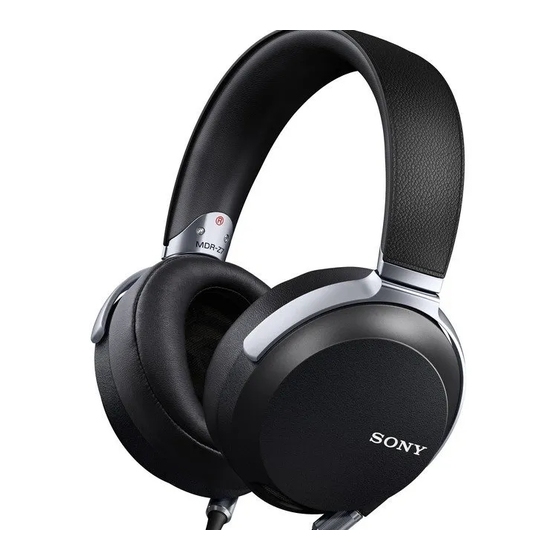
MDR-Z7
Canadian Model
AEP Model
Australian Model
Chinese Model
stereo mini jack) (1)
STEREO HEADPHONES
US Model
UK Model
E Model
Advertisement
Table of Contents

Related Manuals for Sony MDR-Z7


Summary of Contents for Sony MDR-Z7
- Page 1 Gold-plated unimatch plug adaptor (stereo phone plug stereo mini jack) (1) Operating Instructions (1) * IEC = International Electrotechnical Commission Design and specifications are subject to change without notice. STEREO HEADPHONES 9-896-052-01 Sony Corporation 2014I33-1 © 2014.09 Published by Sony Techno Create Corporation...
-
Page 2: Section 1 Servicing Notes
MDR-Z7 SECTION 1 SERVICING NOTES The SERVICING NOTES contains important information for servicing. Be sure to read this section before repairing the unit. DESTINATION ABBREVIATIONS The following abbreviations for model destinations are used in this service manual. • Abbreviations : Australian model... -
Page 3: Section 2 Disassembly
MDR-Z7 SECTION 2 DISASSEMBLY • This set can be disassembled in the order shown below. 2-1. DISASSEMBLY FLOW Note: Please detach the CABLE WITH PLUG beforehand. 2-2. EAR PAD, EAR PAD HOLDER (Page 4) 2-3. HOUSING BLOCK (Page 5) 2-4. FRONT PLATE ASSY (Page 5) 2-5. - Page 4 MDR-Z7 Note: Follow the disassembly procedure in the numerical order given. 2-2. EAR PAD, EAR PAD HOLDER Note 1: L-ch and R-ch can be similarly disassembled. The illustration of R-ch is used for explanation. Note 2: When installing the ear pad block to the housing block, align the ear pad block boss with the housing block ditch.
- Page 5 MDR-Z7 2-3. HOUSING BLOCK Note: L-ch and R-ch can be similarly disassembled. The illustration of R-ch is used for explanation. 1 ornamental screw (M1.7) 1 ornamental screw (M1.7) 2 shaft stopper 3 twist holder 4 axis cushion 5 housing block 2-4.
- Page 6 MDR-Z7 2-5. HOUSING ASSY, HANGER Note 1: L-ch and R-ch can be similarly disassembled. The illustration of R-ch is used for explanation. hanger Align the directions 6 hanger of the slopes. groove axis cushion 5 axis cushion 5 axis cushion...
-
Page 7: Exploded Views
MDR-Z7 SECTION 3 EXPLODED VIEWS Note: • -XX and -X mean standardized parts, so • The mechanical parts with no reference they may have some difference from the number in the exploded views are not sup- original one. plied. • Items marked “*” are not stocked since •... - Page 8 MDR-Z7 3-2. HOUSING (L-ch), HEAD BAND SECTION • Rear view Note: A serial number is marked on the unit’s head band arm. Therefore, when the head band assy is replaced, the serial number changes. – L-ch – – R-ch –...
-
Page 9: Section 4 Accessories
MDR-Z7 SECTION 4 ACCESSORIES Ref. No. Part No. Description Remark 4-538-073-11 MANUAL, INSTRUCTION (ENGLISH, FRENCH, SPANISH) (US, CND) 4-538-073-21 MANUAL, INSTRUCTION (ENGLISH, FRENCH, GERMAN, SPANISH, DUTCH, ITALIAN, PORTUGUESE, POLISH, GREEK, CZECH, HUNGARIAN, BULGARIAN, SLOVAK, SLOVENIAN, ROMANIAN) (AEP, UK) 4-538-073-31 MANUAL, INSTRUCTION... -
Page 10: Revision History
MDR-Z7 REVISION HISTORY Ver. Date Description of Revision 2014.09...