Advertisement
Service Manual
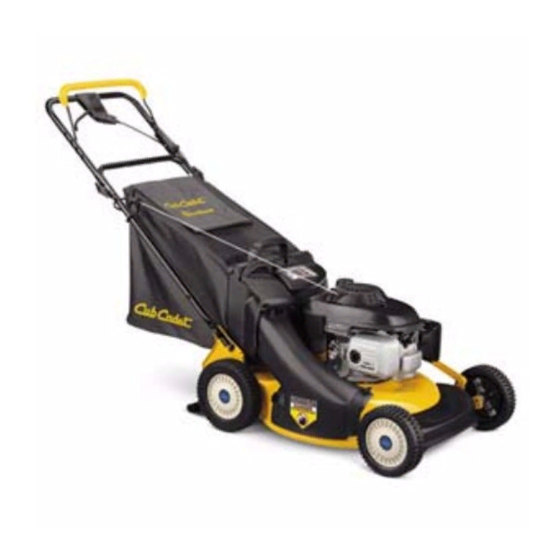
CC-949 Self Propelled Lawn Mower
NOTE: These materials are for use by trained technicians who are experienced in the service and repair of outdoor power
equipment of the kind described in this publication, and are not intended for use by untrained or inexperienced individuals.
These materials are intended to provide supplemental information to assist the trained technician. Untrained or inexperi-
enced individuals should seek the assistance of an experienced and trained professional. Read, understand, and follow all
instructions and use common sense when working on power equipment. This includes the contents of the product's Oper-
ators Manual, supplied with the equipment. No liability can be accepted for any inaccuracies or omission in this publication,
although care has been taken to make it as complete and accurate as possible at the time of publication. However, due to
the variety of outdoor power equipment and continuing product changes that occur over time, updates will be made to these
instructions from time to time. Therefore, it may be necessary to obtain the latest materials before servicing or repairing a
product. The company reserves the right to make changes at any time to this publication without prior notice and without
incurring an obligation to make such changes to previously published versions. Instructions, photographs and illustrations
used in this publication are for reference use only and may not depict actual model and component parts.
© Copyright 2006 MTD Products Inc. All Rights Reserved
MTD Products Inc. - Product Training and Education Department
FORM NUMBER - 769-02121
4/2006
Advertisement

Related Manuals for Cub Cadet CC-949


Summary of Contents for Cub Cadet CC-949
-
Page 1: Service Manual
Service Manual CC-949 Self Propelled Lawn Mower NOTE: These materials are for use by trained technicians who are experienced in the service and repair of outdoor power equipment of the kind described in this publication, and are not intended for use by untrained or inexperienced individuals. -
Page 3: Table Of Contents
Table of Contents INTRODUCTION ........................1 BLADE REMOVAL ........................1 BELT REMOVAL ........................2 TRANSMISSION AND CHAIN CASE REMOVAL ..............4 ENGINE CONTROL CABLE ...................... 6 TRACTION CONTROL CABLE ....................7 FRONT AXLE..........................9... -
Page 5: Introduction
4” or a blade locking tool. See Figure 2.3. 1.3. Description: The CC-949 is a multi-function rear wheel drive self propelled mower. It can bag, mulch or side discharge depending on which chute or plug is attached to the mower. -
Page 6: Belt Removal
Self-Propelled Mower BELT REMOVAL 3.6. Remove the three screws holding the shroud in place using a 3/8” wrench. See Figure 3.6. 3.1. Disconnect and ground the spark plug. 3.2. Take measures to prevent fuel from leaking from Three shroud screws the gas tank. - Page 7 Self-Propelled Mower 3.8. Remove the left rear wheel by removing the hex 3.10. Loosen the bolt that goes through the idler bear- head bolt in the center of the wheel with a 7/16” ing using two 7/16” wrenches. Unlatch the metal wrench.
-
Page 8: Transmission And Chain Case Removal
Self-Propelled Mower TRANSMISSION AND CHAIN CASE 4.7. Remove the nut that holds the height adjuster REMOVAL handle on using a 7/8” wrench. 4.1. Disconnect the spark plug wire and ground it to 4.8. Remove the hairpin clip that holds the height an engine bolt. - Page 9 Self-Propelled Mower 4.11. Remove the screws holding the chain case 4.16. Reassemble the chain case in reverse order. cover on using a 3/8” wrench. See Figure 4.11. 4.17. Remove one of the screws holding the height adjuster spring in place and loosen the other. See Figure 4.17.
-
Page 10: Engine Control Cable
Self-Propelled Mower 4.20. After the handle bar brackets are in place, use a ENGINE CONTROL CABLE piece of starter rope wrapped over the side of 5.1. Make sure the engine is off. the height adjuster spring bracket that the bolt was removed from and pull the spring down until 5.2. -
Page 11: Traction Control Cable
Self-Propelled Mower 5.5. Slide the inner cable through the slot. TRACTION CONTROL CABLE See Figure 5.5. 6.1. Disconnect the spark plug wire and ground it to an engine bolt. Slot 6.2. Take measures to prevent fuel from leaking from the gas tank. 6.3. - Page 12 Self-Propelled Mower 6.8. Remove the mounting cap. See Figure 6.8. 6.10. Slide cable out of the cable ties on the handle bar and discard. Lower handle cover NOTE: If the control lever needs repair take the lower handle cover off and replace the control lever.
-
Page 13: Front Axle
Self-Propelled Mower FRONT AXLE 7.1. Disconnect and ground the spark plug wire. 7.2. Take measures to prevent fuel from leaking from the gas tank. 7.3. Remove the front wheels. 7.4. Remove the hairpin clip that holds the height adjuster linkage from the left front wheel and dis- connect the linkage.