Table of Contents
Advertisement
QQ
3 7 63 1515 0
SERVICE MANUAL
System
Laser: Semiconductor laser
Signal format system:
U.S./Canadian models: NTSC
Asian/Oceanian models: PAL/NTSC
TE
L 13942296513
(See page 1-3 to switch.)
UK/European models: PAL/(NTSC)
Audio characteristics
Frequency response: DVD VIDEO (PCM
96 kHz): 2 Hz to 44 kHz (±1.0 dB)/DVD
VIDEO (PCM 48 kHz): 2 Hz to 22 kHz
(±0.5 dB)/CD: 2 Hz to 20 kHz (±0.5 dB)
Signal-to-noise ratio (S/N ratio): 115 dB
(LINE OUT L/R (AUDIO) jacks only)
Harmonic distortion: 0.003 %
Dynamic range: DVD VIDEO: 103 dB/CD:
99 dB
Wow and flutter: Less than detected value
(±0.001% W PEAK)
The signals from LINE OUT L/R (AUDIO)
jacks are measured. When you play PCM
sound tracks with a 96 kHz sampling
frequency, the output signals from the
DIGITAL OUT (COAXIAL) jack are
converted to 48 kHz sampling frequency.
www
.
http://www.xiaoyu163.com
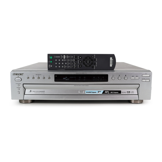
DVP-NC615/NC655P
Photo : DVP-NC655P (SILVER)
Outputs
(Jack name: Jack type/Output level/Load
impedance)
LINE OUT L/R (AUDIO): Phono jack/
2 Vrms/10 kilohms
DIGITAL OUT (COAXIAL): Phono jack/
0.5 Vp-p/75 ohms
DIGITAL OUT (OPTICAL): Optical
output jack/–18 dBm (wave length
660 nm) (UK/European models)
COMPONENT VIDEO OUT(Y, P
C
): Phono jack/Y: 1.0 Vp-p/P
R
C
,: 0.7 Vp-p/75 ohms (US/Canadian/
R
Asian/Oceanian models)
LINE OUT (VIDEO): Phono jack/1.0 Vp-p/
75 ohms
S VIDEO OUT: 4-pin mini DIN/
Y: 1.0 Vp-p/C:0.3 Vp-p (PAL),
0.286 Vp-p (NTSC)/75 ohms
x
ao
u163
y
i
http://www.xiaoyu163.com
2 9
8
RMT-D143A/D143E/D143P/D144A
RMT-D144A
SPECIFICATIONS
Q Q
3
6 7
1 3
1 5
/C
, P
B
B
, P
, C
B
R
co
.
9 4
2 8
US Model
DVP-NC615/NC655P
Canadian Model
AEP Model
UK Model
Australian Model
Singapore Model
PX Model
General
Power requirements:
120 V AC, 60 Hz
110 to 240V AC, 50/60 Hz
220 to 240V AC, 50/60 Hz
0 5
8
2 9
9 4
See page 1-1 for further information.
Power consumption: 13 W/14 W
See page 1-1 for further information.
Dimensions (approx.): 430 × 108 × 409 mm
7 × 4
× 16
(1
3
/
1
/
in.):(NC615: US,
8
8
/
Canadian, Asian, Oceanian models)
R
430 × 108 × 411 mm
(17 × 4
,
B
(NC615: UK, European models)
430 × 108 × 413 mm
(17 × 4
(NC655P model)
(width/height/depth)
incl. projecting parts
Mass (approx.): 5.1 kg (11 lb 4 oz)
Operating temperature: 5 ° C to 35 ° C
°
°
(41
F to 95
F)
Operating humidity: 25 % to 80 %
Supplied accessories
See page 1-3.
Specifications and design are subject to
change without notice.
E
S
R
NERGY
TAR
is a U.S. registered mark.
E
S
As an
NERGY
TAR
R
Corporation has determined that this product
E
S
meets the
NERGY
TAR
energy efficiency.
m
CD/DVD PLAYER
9 9
E Model
DVP-NC615
2 8
9 9
× 16
3
3
in.):
/
/
8
8
× 16
3
1
in.):
/
/
8
4
Partner, Sony
R
guidelines for
Advertisement
Table of Contents
Troubleshooting

Related Manuals for Sony RMT-144A


Summary of Contents for Sony RMT-144A
- Page 1 DIGITAL OUT (COAXIAL) jack are converted to 48 kHz sampling frequency. NERGY is a U.S. registered mark. As an NERGY Partner, Sony Corporation has determined that this product meets the NERGY guidelines for energy efficiency. CD/DVD PLAYER u163 http://www.xiaoyu163.com...
- Page 2 MARK 0 ON THE SCHEMATIC DIAGRAMS AND IN THE PARTS CRITIQUES POUR LA SÉCURITÉ DE FONCTIONNEMENT. NE LIST ARE CRITICAL TO SAFE OPERATION. REPLACE THESE REMPLACER CES COMPOSANTS QUE PAR DES PIÈSES SONY COMPONENTS WITH SONY PARTS WHOSE PART NUMBERS DONT LES NUMÉROS SONT DONNÉS DANS CE MANUEL OU APPEAR AS SHOWN IN THIS MANUAL OR IN SUPPLEMENTS DANS LES SUPPÉMENTS PUBLIÉS PAR SONY.
-
Page 3: Table Of Contents
http://www.xiaoyu163.com 3 7 63 1515 0 TABLE OF CONTENTS SERVICE NOTE Glossary ··············································································· 1-17 Language Code List ····························································· 1-18 NOTE ON REMOVING THE UPPER CASE ··················· 5 DISC REMOVAL PROCEDURE ······································ 5 DISASSEMBLY NOTE ON REMOVING THE TABLE ASS’Y ·················· 5 NOTE ON MOUNTING THE GEARS ·····························... - Page 4 http://www.xiaoyu163.com 3 7 63 1515 0 • ER-14 (LINE1 OUT) (NC615:AEP,UK) 8-1-2. FRONT PANEL SECTION ············································· 8-3 SCHEMATIC DIAGRAM ···························· 4-37 8-1-3. LOADING SECTION ····················································· 8-4 • IF-091 (IF COM), PL-031 (LED) 8-1-4. CHASSIS SECTION ······················································· 8-5 PRINTED WIRING BOARDS ····················· 4-39 8-2.
-
Page 5: Service Note
http://www.xiaoyu163.com SERVICE NOTE 3 7 63 1515 0 NOTE ON REMOVING THE UPPER NOTE ON REMOVING THE TABLE CASE ASS’Y Remove the four tapping screws and three screws. (See Fig. 1) Remove the two screws. (See Fig. 3) Open the sides of case. (See Fig. 1) Remove the upper case in the direction of the arrow A. -
Page 6: Note On Mounting The Gears
http://www.xiaoyu163.com 3 7 63 1515 0 NOTE ON MOUNTING THE GEARS 1) Mount the gear (chuck). (See Fig. 5) 5) Mount the gear (idler) while aligning the engagement of the 2) Rotate the gear (chuck) in the direction of the arrow. (down gear (swing) and the gear (chuck). - Page 7 http://www.xiaoyu163.com 3 7 63 1515 0 HOW TO SERVICE THE MB-103 Remove the upper case from the set. (Refer to section 2-1) Remove the MB-103 board. (Refer to section 2-4) BOARD Set the MB-103 board in the stand (with CK-121 board) as shown in Fig.
- Page 8 http://www.xiaoyu163.com 3 7 63 1515 0 5) Set the four flexible flat cables as shown in Fig. 11. 3 Flexible flat cable (FFC 11P: CN201) 2 Flexible flat cable (FFC 9P: CN204) 4 Connector (CN102) 1 Flexible flat cable (FFC 26P: CN203) 5 Connector 7 Flexible flat cable (CN104)
-
Page 9: Connection Of Service Jig
http://www.xiaoyu163.com 3 7 63 1515 0 CONNECTION OF SERVICE JIG AV-62 board CN201 FFC25P CK-120 board CN601 FFC 26P (Used the set) FFC 26P CN101 CN102 CN203 FFC 9P (Used the set) FFC 9P CN103 CN104 CN204 Mechanism deck MB-103 board FFC 11P CN107... - Page 10 http://www.xiaoyu163.com 3 7 63 1515 0 MEMO L 13942296513 u163 — 10 — http://www.xiaoyu163.com...
-
Page 11: General
• To prevent fire or shock hazard, do not damp room, moisture may condense on the nearest Sony dealer. place objects filled with liquids, such as lenses inside the player. Should this occur, vases, on the apparatus. - Page 12 http://www.xiaoyu163.com 3 7 63 1515 0 Front panel display Index to Parts and Controls When playing back a DVD For more information, refer to the pages indicated in parentheses. Playing status Lights up when you can Front panel Disc numbers (29) change the angle (50) Playing time (45) Disc type...
- Page 13 http://www.xiaoyu163.com 3 7 63 1515 0 Displaying the Control Bar in 7 8 9 q; Guide to On-Screen NDisplay 4 stop mode Displays (Control Bar) Shows the same information as Display 3 The following displays appear when the during playback. DISPLAY button is repeatedly pressed The following explains the Control Bar.
-
Page 14: Step 4: Playing A Disc
http://www.xiaoyu163.com 3 7 63 1515 0 Step 4: Playing a Disc Hookups Hooking Up the Player Follow Steps 1 to 4 to hook up and adjust the settings of the player. Before you start, disconnect the power cords, check that you have all of the supplied accessories, and insert the batteries into the remote (page 15). - Page 15 http://www.xiaoyu163.com 3 7 63 1515 0 Connecting to your TV Connecting to a stereo amplifier (receiver) and 2 speakers/Connecting to an MD deck or DAT deck This connection will use your TV speakers for sound. If the stereo amplifier (receiver) has audio input jacks L and R only, use .
-
Page 16: Step 3: Connecting The Power Cord
http://www.xiaoyu163.com 3 7 63 1515 0 Press X/x to select the setting that AUDIO SETUP AUDIO ATT: Step 3: Connecting the Power Cord matches your TV type. AUDIO DRC: STANDARD DOWNMIX: DOLBY SURROUND N If you have a 4:3 standard TV DIGITAL OUT: DOLBY DIGITAL: D-PCM... -
Page 17: Resuming Playback From The Point Where You Stopped The Disc (Resume Play/Multi-Disc Resume)
http://www.xiaoyu163.com 3 7 63 1515 0 z Hints be connected to the digital jack of the Additional operations Note • The Replay function is useful when you want to player. review a scene or dialog that you missed. • Set the sound to “STEREO” using the Do not push the disc tray to close in Step 5, as you •... -
Page 18: Q Q
http://www.xiaoyu163.com 3 7 63 1515 0 z Hint To play without using PBC, press ./> while Using the DVD’s Menu Playing VIDEO CDs with Playing an MP3 Audio the player is stopped to select a track, then press H PBC Functions Track or ENTER. -
Page 19: Various Play Mode Functions
http://www.xiaoyu163.com 3 7 63 1515 0 Press C/c to select Disc mode Various Play Mode (PROGRAM), then press ENTER. PROGRAM 3 : DVD The display for programming appears. Functions ALL CLEAR (Program Play, 1. – – – – – PROGRAM 2. -
Page 20: Searching For A Scene
http://www.xiaoyu163.com 3 7 63 1515 0 N When playing a VIDEO CD or CD To return to normal play Repeating a specific portion (A- • DISC: repeats all of the tracks on the Press CLEAR. B Repeat Play) current disc in One Disc mode, or all of To turn off the Control Bar the discs in All Discs mode. -
Page 21: Sound Adjustments
NTVS NIGHT R: right) without using actual rear speakers. • TVS STANDARD Rear (L/R) TVS was developed by Sony to produce Large sounds, such as explosions, are suppressed, but the quieter sounds are surround sound for home use using just a TVS DYNAMIC unaffected. -
Page 22: Enjoying Movies
http://www.xiaoyu163.com 3 7 63 1515 0 • “TVS NIGHT” only works with Dolby Digital Displaying the Subtitles and MPEG audio discs. However, not all discs will respond to the “TVS NIGHT” function in the Enjoying Movies same way. • If you use the DIGITAL OUT (COAXIAL) jack Changing the Angles and set “DOLBY DIGITAL”... -
Page 23: Enhancing The Playback Picture
http://www.xiaoyu163.com 3 7 63 1515 0 To cancel the “DIGITAL VIDEO • DYNAMIC 2: produces a more Enhancing the Playback dynamic picture than DYNAMIC 1 by ENHANCER” setting further increasing the picture contrast Select “OFF” in Step 2. Picture (DIGITAL VIDEO and the color intensity. -
Page 24: Controlling Your Tv With The Supplied Remote
You can control the sound level, input source, If your TV is listed in the table below, set the Press O RETURN. Manufacturer Code number and power switch of your Sony TV with the appropriate manufacturer’s code. supplied remote. Sony (default) To turn off the display... -
Page 25: Settings And Adjustments
http://www.xiaoyu163.com 3 7 63 1515 0 Press X/x to select “CUSTOM,” Select a setting using X/x, then Setting the Display or then press ENTER. press ENTER. Settings and Adjustments Sound Track Language The Setup Display appears. The setting is selected and setup is complete. -
Page 26: Settings For The Sound (Audio Setup)
MPEG Select this when the player is , The amplifier (receiver) input is not Sony dealer. connected to an audio correctly set. component with a built-in , The player is in pause mode or in Slow- Power MPEG decoder. -
Page 27: Self-Diagnosis Function
LOCKED” appears on the front panel play a DATA CD. display. be changed. , Contact your Sony dealer or local , Try using the DVD’s menu instead of the “Data error” , The MP3 audio track you want to play is authorized Sony service facility. -
Page 28: Language Code List
http://www.xiaoyu163.com 3 7 63 1515 0 Language Code List For details, see pages 46, 50, 62. The language spellings conform to the ISO 639: 1988 (E/F) standard. Code Language Code Language Code Language Code Language 1027 Afar 1183 Irish 1347 Maori 1507 Samoan 1028 Abkhazian 1186 Scots Gaelic... -
Page 29: Disassembly
http://www.xiaoyu163.com DVP-NC615/NC655P SECTION 2 DISASSEMBLY 3 7 63 1515 0 2-1. DISASSEMBLY • This set can be disassembled in the order shown below. Upper case (Page 2-1) Front panel section Rear panel section MB-103 board CN-158 board Power block (Page 2-1) (Page 2-2) (Page 2-2) (Page 2-3) -
Page 30: Front Panel Section
http://www.xiaoyu163.com 3 7 63 1515 0 2-3. FRONT PANEL SECTION 3 Two screws (B3) 1 Flexible flat cable (FCI-1: CN303) 4 Claw 2 Two screws (B3) 5 Claw 6 Front panel section L 13942296513 2-4. REAR PANEL 8 Screw (B3) 9 Rear panel 3 Connector (CN101) -
Page 31: Board
http://www.xiaoyu163.com 3 7 63 1515 0 2-5. MB-103 BOARD 8 Flexible flat cable (FMM-42: CN203) 9 Four screws (B3) 7 Flexible flat cable (FMO-6: CN204) 6 Connector 0 MB-103 board (CN102) 2 Pull the tray in the direction of the arrow B. 5 Flexible flat cable (FMV-20: CN601) 4 Board to board connector... -
Page 32: Board
http://www.xiaoyu163.com 3 7 63 1515 0 2-7. AV-062 BOARD 2 Six screws (B3)(NC655P) 1 Flexible flat cable Five screws (FAE-10: CN101) (B3)(NC615) (AEP, UK) 3 AV-062 board 2-8. ER-14 BOARD (AEP, UK) 2 Two screws (B3) 1 Flexible flat cable (FAE-10: CN901) L 13942296513 3 ER-14 board... -
Page 33: Loading Motor Ass'y
http://www.xiaoyu163.com 3 7 63 1515 0 2-10. LOADING MOTOR ASS’Y 6 Belt (timing) 8 Screw (M2.6 × 4) 3 MD-94 board 1 Screw (M2.6 × 8) 7 Screw (M2.6 × 4) 9 Loading motor assembly (M901) 4 Connector (CN004) 2 Claw 5 Claws L 13942296513 2-11. - Page 34 http://www.xiaoyu163.com 3 7 63 1515 0 2-12.POWER BLOCK 3 Harness 5 Two claws 7 Power block 2 Connector 6 Holder, PS (CN101) 1 Connector (CN201) 4 Two screws (B3) L 13942296513 2-13.IF-091 AND FR-187 BOARDS 3 Nine screws (M2.6 × 8) 8 Board to board connector (CN403, CN701) 2 Four screws...
- Page 35 http://www.xiaoyu163.com 3 7 63 1515 0 2-14.INTERNAL VIEWS PH101 (on the SE-130 board) PH102 Optical pick-up (on the SE-130 board) (KHM-270AAA/Service assembly) A-6062-709-A TD unit ass'y A-6060-640-A L 13942296513 Encoder ass'y (loading) X-3952-380-1 u163 M901 Loading motor ass'y X-3952-378-1 http://www.xiaoyu163.com...
-
Page 36: Power Block
http://www.xiaoyu163.com 3 7 63 1515 0 2-15.CIRCUIT BOARDS LOCATION POWER BLOCK (SWITCHING REGULATOR) SE-130 board (SENSOR) ER-14 board MD-94 board (LINE1 OUT) (MD INTERFACE) AV-062 board (AUDIO/VIDEO OUT) FR-187 board MB-103 board (FUNCTION SW/LED) DVD/CD RF AMP, DIGITAL SERVO, MOTOR DRIVE, AV DECODER, PL-031 board SDRAM, SYSTEM CONTROL, (LED) -
Page 37: Block Diagrams
http://www.xiaoyu163.com DVP-NC615/NC655P SECTION 3 BLOCK DIAGRAMS 3 7 6 3 1 5 1 5 0 3-1. OVERALL BLOCK DIAGRAM MB-103 BOARD AV-62 BOARD *IC405 : AEP,UK (SEE PAGE 4-11 to 4-26) (SEE PAGE 4-31 to 4-34) NC655P IC404,405 * EXCEPT AEP,UK IC503 16M SDRAM J102... -
Page 38: Rf/Servo Block Diagram
http://www.xiaoyu163.com DVP-NC615/NC655P 3 7 6 3 1 5 1 5 0 3-2. RF/SERVO BLOCK DIAGRAM MB-103 BOARD (1/4) IC202 (DVD play) IC202 (CD play) IC202 (DVD play) IC202 (CD play) (SEE PAGE 4-11, 13, 19) 500 mV/DIV 50 ns/DIV 500 mV/DIV 200 ns/DIV BASE UNIT 100 mV/DIV 50 ms/DIV 500 mV/DIV 50 ms/DIV... -
Page 39: Signal Processor Block Diagram
http://www.xiaoyu163.com DVP-NC615/NC655P 3 7 6 3 1 5 1 5 0 3-3. SIGNAL PROCESSOR BLOCK DIAGRAM MB-103 BOARD (2/4) (SEE PAGE 4-13 to 4-18) IC504, 505* *IC405: AEP,UK,NC655P 16M SDRAM IC303 16M DRAM NC615 ONLY IC503 IC503 : AEP, UK : EXCEPT AEP, UK (LINE : RGB mode) 135-138 140-143... -
Page 40: System Control Block Diagram
http://www.xiaoyu163.com DVP-NC615/NC655P 3 7 6 3 1 5 1 5 0 3-4. SYSTEM CONTROL BLOCK DIAGRAM MB-103 BOARD (3/4) (SEE PAGE 4-21 to 4-24) IC108 IC106 IC107 IM SRAM FLASH HA 0 – 21 HA 0 – 21 HD 0 – 15 HD 0 –... -
Page 41: Video Block Diagram (Nc655P)
http://www.xiaoyu163.com DVP-NC615/NC655P 3 7 6 3 1 5 1 5 0 3-5. VIDEO BLOCK DIAGRAM (NC655P) AV-62 BOARD MB-103 BOARD J101 VIDEO 1 LINE OUT MCLOCK VIDEO 2 ı J103 DVD 0 – 7 ı PI 2 - 9 SIGNAL AO 0 –... -
Page 42: Video Block Diagram (Nc615)
http://www.xiaoyu163.com DVP-NC615/NC655P 3 7 6 3 1 5 1 5 0 3-6. VIDEO BLOCK DIAGRAM (NC615) IC102 : AEP, UK AV-62 BOARD (1/2) * IC102 36 pin : EXCEPT AEP, UK : EXCEPT AEP, UK J101 (1/2) (SEE PAGE 4-31) 24 pin : AEP, UK EXCEPT AEP, UK IC102... -
Page 43: Audio Block Diagram
http://www.xiaoyu163.com DVP-NC615/NC655P 3 7 6 3 1 5 1 5 0 3-7. AUDIO BLOCK DIAGRAM AV-62 BOARD (2/2) (SEE PAGE 4-33) MB-103 BOARD (4/4) IC204 (SEE PAGE 4-25) OPTICAL DIGITAL OUT 1 D IN OPTICAL DIGITAL CN601 (3/3) CN201 (2/2) J201 SPDIF Q201... -
Page 44: Interface Control Block Diagram
http://www.xiaoyu163.com DVP-NC615/NC655P 3 7 6 3 1 5 1 5 0 3-8. INTERFACE CONTROL BLOCK DIAGRAM IF-91 BOARD FR-187 BOARD (SEE PAGE 4-41) (SEE PAGE 4-45) NC655P IC404 IC406 IF CON REMOTE COMMANDER RECEIVER CN407 AUDIO (SEE PAGE 3-14) A MUTE /AMUTE IC702 LED DRIVE... -
Page 45: Power Block Diagram (1/2)
http://www.xiaoyu163.com DVP-NC615/NC655P 3 7 6 3 1 5 1 5 0 3-9. POWER BLOCK DIAGRAM (1/2) HS10S1U/F BOARD T101 (SEE PAGE 4-57) CN201 D221 L221 EVER+11V Q211 AC IN CN101 D101 D211 L211 F101 SW+11V L101 L102 SW +5V • LINE LINE FILTER... -
Page 46: Power Block Diagram (2/2)
http://www.xiaoyu163.com DVP-NC615/NC655P 3 7 6 3 1 5 1 5 0 3-10. POWER BLOCK DIAGRAM (2/2) FR-187 BOARD (SEE PAGE 4-45) NC655P ONLY D709 AEP, UK ER-14 BOARD AV-62 BOARD (SEE PAGE 4-37) (SEE PAGE 4-31 to 4-34) D710 CN101 CN901 IC901 L905... -
Page 47: Printed Wiring Boards And Schematic Diagrams
http://www.xiaoyu163.com DVP-NC615/NC655P SECTION 4 PRINTED WIRING BOARDS AND SCHEMATIC DIAGRAMS 3 7 6 3 1 5 1 5 0 4-1. FRAME SCHEMATIC DIAGRAM OPTICAL PICK-UP UNIT FOCUS/TRACKING ER-14 DVD/CD PD IC COIL SLED MOTOR SPINDLE MOTOR BOARD CNJ902 LIN(RGB)-TV NC615: AEP,UK FAE-10 FLAT CABLE FMO-6... - Page 48 http://www.xiaoyu163.com DVP-NC615/NC655P 3 7 6 3 1 5 1 5 0 4-2. PRINTED WIRING BOARDS AND SCHEMATIC DIAGRAMS THIS NOTE IS COMMON FOR WIRING BOARDS AND SCHEMATIC DIAGRAMS (In addition to this, the necessary note is printed in each block) (For printed wiring boards) (For schematic diagrams) •...
-
Page 49: Waveforms
http://www.xiaoyu163.com DVP-NC615/NC655P 3 7 6 3 1 5 1 5 0 MB-103 AV-062 IF-091 BOARD BOARD BOARD IC104 tf IC102 ed IC404 3 1.7Vp-p 3.8Vp-p 2.0Vp-p 124nsec 60.6nsec IC103 3,8 IC102 ea 4.4Vp-p 37nsec 640mVp-p IC103 9,q; IC102 wl 4.0Vp-p 1.0Vp-p 40.7nsec IC103 qd,qg... - Page 50 http://www.xiaoyu163.com DVP-NC615/NC655P 3 7 6 3 1 5 1 5 0 MB-103 (DVD/CD RF AMP, DIGITAL SERVO, MOTOR DRIVE, SERVO, AV DECODER, SDRAM, SYSTEM CONTROL, AUDIO DAC, PLL, I/P CONVERTER, VIDEO ENCODER) PRINTED WIRING BOARD MB-103 BOARD (SIDE A) • : Uses unleaded solder.
- Page 51 http://www.xiaoyu163.com DVP-NC615/NC655P 3 7 6 3 1 5 1 5 0 MB-103 BOARD (SIDE B) • : Uses unleaded solder. D201 D202 IC101 IC103 IC106 IC107 IC108 IC201 IC202 IC303 IC401 IC404 IC405 IC503 IC504 IC505 Q201 Q202 1 3 9 4 2 2 9 6 5 1 3 w w w u 1 6 3 DVD/CD RF AMP, DIGITAL SERVO, MOTOR DRIVE, SERVO, AV DECODER, SDRAM, SYSTEM CONTROL, AUDIO DAC, PLL, I/P CONVERTER, VIDEO ENCODER...
-
Page 52: Dvd/Cd Rf Amp, Digital Servo
http://www.xiaoyu163.com DVP-NC615/NC655P 3 7 6 3 1 5 1 5 0 For Schematic Diagram • Refer to page 4-7 for printed wiring board. MB-103 BOARD(1/8) DVD/CD RF AMP DIGITAL SERVO CN202 -REF.NO.:1000 SERIES- XX MARK:NO MOUNT NO MARK:PB MODE SIGNAL PATH VIDEO SIGNAL AUDIO SIGNAL... -
Page 53: Motor Drive
http://www.xiaoyu163.com DVP-NC615/NC655P 3 7 6 3 1 5 1 5 0 For Schematic Diagram • Refer to page 4-7 for printed wiring board. MB-103 BOARD(2/8) MOTOR DRIVE -REF.NO.:1000 SERIES- XX MARK:NO MOUNT SIGNAL PATH NO MARK:PB MODE +3.3V SPINDLE SERVO (SPEED AND PHASE) TRACKING SERVO DVD/CD CDV TO(7/8) R259... -
Page 54: Servo
http://www.xiaoyu163.com DVP-NC615/NC655P 3 7 6 3 1 5 1 5 0 For Schematic Diagram • Refer to page 4-7 for printed wiring board. MB-103 BOARD(3/8) SERVO -REF.NO.:1000 SERIES- XX MARK:NO MOUNT NO MARK:PB MODE FL302 R351 +1.8V FL301 R301 R352 (2012) +3.3V R302... -
Page 55: Av Decoder
http://www.xiaoyu163.com DVP-NC615/NC655P 3 7 6 3 1 5 1 5 0 For Schematic Diagram • Refer to page 4-7 for printed wiring board. MB-103 BOARD(4/8) AV DECODER -REF.NO.:1000 SERIES- XX MARK:NO MOUNT XWRH XAVDIT NO MARK:PB MODE XWAIT SIGNAL PATH TO(6/8) DACK0 DREQ0... -
Page 56: Sdram
http://www.xiaoyu163.com DVP-NC615/NC655P 3 7 6 3 1 5 1 5 0 For Schematic Diagram • Refer to page 4-7 for printed wiring board. MB-103 BOARD(5/8) NO MARK:PB MODE SDRAM -REF.NO.:1000 SERIES- XX MARK:NO MOUNT ADDT0 ADDT0 ADDT15 C437 IC404 HY57V16161 ADDT15 ADDT1 ADDT1... -
Page 57: System Control
http://www.xiaoyu163.com DVP-NC615/NC655P 3 7 6 3 1 5 1 5 0 For Schematic Diagram • Refer to page 4-7 for printed wiring board. • Refer to page 4-5 for waveform. MB-103 BOARD(6/8) SYSTEM CONTROL -REF.NO.:1000 SERIES- XX MARK:NO MOUNT NO MARK:REC/PB MODE +3.3V TO(7/8) FL106... -
Page 58: Audio Dac, Pll
http://www.xiaoyu163.com DVP-NC615/NC655P 3 7 6 3 1 5 1 5 0 For Schematic Diagram • Refer to page 4-7 for printed wiring board. • Refer to page 4-5 for waveform. (DVP-NC655P) (DVP-NC615) R613 R612 MB-103 BOARD(7/8) PR_V COMPOUT R614 FB602 PR_C COUT AUDIO DAC,PLL... -
Page 59: I/P Converter, Video Encoder
http://www.xiaoyu163.com DVP-NC615/NC655P 3 7 6 3 1 5 1 5 0 For Schematic Diagram • Refer to page 4-7 for printed wiring board. MB-103 BOARD(8/8) (DVP-NC655P ONLY) NO MARK:REC/PB MODE IP CONVERTER,VIDEO ENCODER -REF.NO.: SERIES- XX MARK:NO MOUNT R511 R536 TO(6/8) C513 0.01u... - Page 60 http://www.xiaoyu163.com DVP-NC615/NC655P 3 7 6 3 1 5 1 5 0 For printed wiring board AV-062 BOARD CN101 A-4 IC204 There are a few cases that the part printed on CN201 A-3 this diagram isn’t mounted in this model. CN202 A-1 Q104 Q105 D101...
-
Page 61: Audio Out, Video Out) Printed Wiring Board
http://www.xiaoyu163.com DVP-NC615/NC655P 3 7 6 3 1 5 1 5 0 AV-062 (AUDIO OUT, VIDEO OUT) PRINTED WIRING BOARD • : Uses unleaded solder. DIGITAL OUT LINE OUT COMPONENT DIGITAL OUT (OPTICAL) VIDEO OUT (COAXIAL) (R - AUDIO - L) (VIDEO) PROG S VIDEO... - Page 62 http://www.xiaoyu163.com DVP-NC615/NC655P 3 7 6 3 1 5 1 5 0 For Schematic Diagram • Refer to page 4-29 for printed wiring board. AV-62 BOARD(1/2) R213 AUDIO OUT 4700 R220 ± 0.5% 2200 C216 0.01u -REF.NO.:2000 SERIES- C210 R224 560p R230 5600 XX MARK:NO MOUNT...
- Page 63 http://www.xiaoyu163.com DVP-NC615/NC655P 3 7 6 3 1 5 1 5 0 For Schematic Diagram • Refer to page 4-29 for printed wiring board. • Refer to page 4-5 for waveforms. AV-62 BOARD(2/2) JL117 SW_-13V NOT USE VIDEO OUT -REF.NO.:2000 SERIES- JL129 XX MARK:NO MOUNT JL126...
-
Page 64: Line1 Out) (Nc615:Aep,Uk) Printed Wiring Board
http://www.xiaoyu163.com DVP-NC615/NC655P 3 7 6 3 1 5 1 5 0 ER-14 (LINE1 OUT) PRINTED WIRING BOARD • : Uses unleaded solder. LINE (RGB)-TV 1 3 9 4 2 2 9 6 5 1 3 For printed wiring board POWER BLOCK (SWITCHING REGULATOR) SE-130 board (SENSOR) - Page 65 http://www.xiaoyu163.com DVP-NC615/NC655P 3 7 6 3 1 5 1 5 0 ER-14 BOARD (AEP,UK MODEL ONLY) LINE1 OUT -REF.NO.: SERIES- L905 100uH XX MARK:NO MOUNT CN901 JL933 IC901 JL934 R956 SIGNAL PATH C913 0.22u JL935 VIDEO BUFFER, SELECT SWITCH JL936 VIDEO SIGNAL C905 R936...
- Page 66 http://www.xiaoyu163.com DVP-NC615/NC655P 3 7 6 3 1 5 1 5 0 IF-091 (IF COM), PL-031 (LED) PRINTED WIRING BOARDS • : Uses unleaded solder. DISPLAY RETURN (REMOTE SENSOR) MENU (PAUSE) (STOP) (PREV) (NEXT) DISC SKIP (OPEN) 1 3 9 4 2 2 9 6 5 1 3 For printed wiring board IF-091 BOARD POWER BLOCK...
- Page 67 http://www.xiaoyu163.com DVP-NC615/NC655P 3 7 6 3 1 5 1 5 0 IF-91 BOARD CN407 IF COM SW+3.3V SW-11V -REF.NO.: SERIES- EVER+3.3V XX MARK:NO MOUNT AMUTE R456 NO MARK:REC/PB MODE :Cannot be measured P-CONT VMUTE CN-158 BOARD CN303 (FCI-1 FLAT CABLE) IFRST (SEE PAGE 4-50) 3.3VMNT...
- Page 68 http://www.xiaoyu163.com DVP-NC615/NC655P 3 7 6 3 1 5 1 5 0 FR-187 (FUNCTION SW/LED) PRINTED WIRING BOARD • : Uses unleaded solder. For printed wiring board FR-187 BOARD D701 IC702 There are a few cases that the part printed on D702 this diagram isn’t mounted in this model.
- Page 69 http://www.xiaoyu163.com DVP-NC615/NC655P 3 7 6 3 1 5 1 5 0 R705 R707 R710 R712 FR-187 BOARD 8200 2700 3900 R723 R709 R713 R715 FUNCTION SW/LED 8200 3900 2700 -REF.NO.: SERIES- XX MARK:NO MOUNT NO MARK:REC/PB MODE LOAD SURROUND PICTURE 1/ALL MODE (ON/STBY)
- Page 70 http://www.xiaoyu163.com DVP-NC615/NC655P 3 7 6 3 1 5 1 5 0 CN-158 (CONNECTOR) PRINTED WIRING BOARD • : Uses unleaded solder. 1 3 9 4 2 2 9 6 5 1 3 For printed wiring board CN-158 BOARD POWER BLOCK (SWITCHING REGULATOR) SE-130 board CN301 A-2...
- Page 71 http://www.xiaoyu163.com DVP-NC615/NC655P 3 7 6 3 1 5 1 5 0 CN-158 BOARD FB307 CONNECTOR CN303 JL349 -REF.NO.: SERIES- SW+3.3V XX MARK:NO MOUNT SW-11V NO MARK:REC/PB MODE EVER+3.3V CN308 AMUTE P-CONT JL398 XFRRST VMUTE JL397 +3.3V_MNT JL396 IF-91 BOARD FB305 CN407 XIFCS IFRST...
- Page 72 http://www.xiaoyu163.com DVP-NC615/NC655P 3 7 6 3 1 5 1 5 0 SE-130 (SENSOR), MD-94 (MD INTERFACE) PRINTED WIRING BOARDS • : Uses unleaded solder. 1 3 9 4 2 2 9 6 5 1 3 For printed wiring board There are a few cases that the part printed on this diagram isn’t mounted in this model.
- Page 73 http://www.xiaoyu163.com DVP-NC615/NC655P 3 7 6 3 1 5 1 5 0 MD-94 BOARD MD INTERFACE -REF.NO.:1000 SERIES- XX MARK:NO MOUNT CN001 OCSW2 CN003 OCSW1 OCSW1 CKSW1 CKSW1 SGND SGND SENSOR LED CN-158 BOARD ROTARY CN305 ENCODER TSENS (SEE PAGE 4-50) DSENS CN004 M001...
- Page 74 http://www.xiaoyu163.com DVP-NC615/NC655P 3 7 6 3 1 5 1 5 0 HS10S1U, HS10S1F (SWITCHING REGULATOR) PRINTED WIRING BOARD POWER BOARD (SW REG) • : Uses unleaded solder. (HS10S1U) (NC615: US,CND/NC655P) 1 3 9 4 2 2 9 6 5 1 3 1-468-641- POWER BOARD (SW REG) (HS10S1F)
- Page 75 http://www.xiaoyu163.com DVP-NC615/NC655P 3 7 6 3 1 5 1 5 0 POWER BOARD (SW REG) (HS10S1U): NC615: US,CND/NC655P (HS10S1F): NC615: PX,E,AEP,UK,AUS,SP Q211 T101 2SJ525 L211 D211 39uH R212 D313 C211 C213 R211 R613 HS10S1F 220u 1.5k D213 R313 Z150 C110 HS10S1F: 150u/400V L221...
- Page 76 http://www.xiaoyu163.com 3 7 6 3 1 5 1 5 0 MEMO 1 3 9 4 2 2 9 6 5 1 3 w w w u 1 6 3 4-60E http://www.xiaoyu163.com...
-
Page 77: System Control Pin Function
http://www.xiaoyu163.com DVP-NC615/NC655P SECTION 5 IC PIN FUNCTION DESCRIPTION 3 7 63 1515 0 5-1. SYSTEM CONTROL PIN FUNCTION (MB-103 BOARD IC104: MB91307RPFV-G-BND-E1) Pin No. Pin Name Function HA17-HA21 Address bus A17 to A21 HA22 – Not used I2C EEPROM write protect output XSACS –... - Page 78 http://www.xiaoyu163.com 3 7 63 1515 0 Pin No. Pin Name Function – Power supply (+3.3 V) CKSW1 Chuck sensor input OCSW1 Tray sensor input CS0X External ROM chip select signal output XRAMCS External RAM chip select signal output CS2X AV DEC chip select signal output CS3X AV DEC chip select signal output CS4X...
-
Page 79: Test Mode
http://www.xiaoyu163.com DVP-NC615/NC655P SECTION 6 TEST MODE 3 7 63 1515 0 6-1. GENERAL DESCRIPTION 6-3. SYSCON DIAGNOSIS The Test Mode allows you to make diagnosis and adjustment eas- The same contents as board detail check by serial interface can be ily using the remote commander and monitor TV. - Page 80 http://www.xiaoyu163.com 3 7 63 1515 0 To quit the diagnosis and return to the Check Menu screen, press General Description of Checking Method x or [ENTER] key. If an error occurred, the diagnosis is suspended 2. Version and the error code is displayed as shown below. (2-2) Revision ROM revision number is displayed.
- Page 81 http://www.xiaoyu163.com 3 7 63 1515 0 4. Servo (5-4) ARP to RAM Address Bus Data write t other address read discord check (4-2) Servo DSP Check Error 10: ARP Tt RAM address bus error Data write t read, and accord check Caution: Address and data display in case of an error is Error 12: Read data discord different from the display of other diagnosis (described...
- Page 82 http://www.xiaoyu163.com 3 7 63 1515 0 6. AV Decoder 8. Audio Output (8-2) ARP t1935 (6-2) 1935 RAM Data write t read, and accord check Data flow from supply system DRAM to SDRAM of AV Error 14: AVD RAM read data discord Decoder is tested.
- Page 83 http://www.xiaoyu163.com 3 7 63 1515 0 Error Codes List 6-4. DRIVE AUTO ADJUSTMENT 00: Error not detected On the Test Mode Menu screen, press [1] key on the remote com- 01: RAM write/read data discord mander, and the drive auto adjustment menu will be displayed. 03: EEPROM NG 04: Flash memory clear error ## Drive Auto Adjustment ##...
- Page 84 http://www.xiaoyu163.com 3 7 63 1515 0 1. DVD Single Layer Disc 3. DVD Dual Layer Disc Select [1], insert DVD single layer disc, and press [ENTER] key, Select [3], insert DVD dual layer disc, and press [ENTER] key, and and the adjustment will be made through the following steps, then the adjustment will be made through the following steps, then ad- adjusted values will be written to the EEPROM.
- Page 85 http://www.xiaoyu163.com 3 7 63 1515 0 0. Disc Check Memory 6-5. DRIVE MANUAL OPERATION On the Test Mode Menu screen, select [2], and the manual opera- Disc Check tion menu will be displayed. For the manual operation, each servo on/off control and adjustment can be executed manually. 1.
-
Page 86: Tel 13942296513
http://www.xiaoyu163.com 3 7 63 1515 0 2. Servo Control Once the disc type has been selected, the sector address or time code display field will appear as shown below. These values are displayed when PLL is locked. Servo Control 1. LD R. -
Page 87: Q Q
http://www.xiaoyu163.com 3 7 63 1515 0 3. Track/Layer Jump 4. Manual Adjustment Track/Layer Jump Manual Adjustment:Up/Down 1. 1Tj FWD R. Fj (L1->L0) 1. TRK. Offset 2. 1Tj REV L. Fj (L0->L1) 2. Focus Gain 3. 2Tj FWD U. Lj (L1->L0) 3. - Page 88 http://www.xiaoyu163.com 3 7 63 1515 0 5. Auto Adjustment 6. Memory Check The display image is shown below and three screens in total can be selected. Auto Adjustment 1. Auto TRK. Offset DL 2. Auto Focus Balance EEPROM DATA 1 3.
-
Page 89: Mecha Aging
http://www.xiaoyu163.com 3 7 63 1515 0 6-6. MECHA AGING 6-8. VERSION INFORMATION ### Version Infomation ### ### Mecha Aging ### IF con. Ver.x.xxx(xxxx) Group SYScon. Ver.x.xxx(xxxx) Press OPEN key Model Region 0x Servo DSP Ver:x.xxx AVD ucode Ver:xxxxxxxx Abort : STOP key OPT TYPE : x LASER Exit : RETURN On the Test Mode Menu screen, selecting [3] executes the aging... -
Page 90: If Con Self Diagnostic Function
http://www.xiaoyu163.com 3 7 63 1515 0 2. OPERATION OF SELF CHECK MODE 6-10. IF CON SELF DIAGNOSTIC FUNCTION The Self Check mode is the function to conduct the basic test to the FL display and DVD panel section. 1. IF-91 BOARD (IF CON) TEST MODE The front board test mode is the IF CON self diagnostic mode. - Page 91 http://www.xiaoyu163.com 3 7 63 1515 0 2-2. Operation of Auto Self Check When the Self Check mode becomes active at the AC Power ON or by key input, the test display of the following steps (1) to (4) is repeated. (1) FLD and LED all ON (for 5 seconds) (2) MODEL display (for 2 seconds) (3) Version display (for 2 seconds)
- Page 92 http://www.xiaoyu163.com 3 7 63 1515 0 2-3. Each Self Check Function Each Self Check function tests the FLD display, LED display, and key input. IC404: Pin No. (Signal) Input Voltage [V] (AD1) (AD2) (AD4) (AD5) (AD6) (AD7) Pin ea Pin es Pin ef Pin eg Pin eh...
- Page 93 http://www.xiaoyu163.com 3 7 63 1515 0 Key code display (at input of [PLAY] key, Key code: 0Ah) At input of faulty voltage When two keys are pressed 2-3-3. Remote Commander Key Name Display and Key Code Display 2-3-3-1. Transition Keys in Self Check Mode Remote commander keys except keys transited in self check 2-3-3-2.
- Page 94 http://www.xiaoyu163.com 3 7 63 1515 0 2-3-4. Communication Monitoring Display The communication state is monitored and displayed while the key name on the main unit and the remote commander is displayed. When the communication to the System Controller failed, VCD, DVD, and CD segments turn on.
- Page 95 http://www.xiaoyu163.com 3 7 63 1515 0 2-3-6. FLD Grid Test Display and SHUTTLE Click Operation Test 2-3-6-1. Transition Keys in Self Check Mode • [UP] on the main unit and the remote commander • SHUTTLE on the remote commander during Grid Test display (This model does not provide JOG/SHUTTLE, and therefore use another DVD remote commander having the JOG/ SHUTTLE)
- Page 96 http://www.xiaoyu163.com 3 7 63 1515 0 GRID ASSIGNMENT (13G-1G) L 13942296513 ANODE CONNECTION DISC u163 6-18 http://www.xiaoyu163.com...
-
Page 97: Troubleshooting
http://www.xiaoyu163.com 3 7 63 1515 0 1-3. Clock signal check 6-11. TROUBLESHOOTING Measure the clock signal frequency at CPUCK (CL101) of 6-11-1. Cannot Enter Test Mode SYSCON (IC104) with an oscilloscope. You cannot enter the Test mode when either button has been pressed If the 8.25 MHz signal appears. - Page 98 http://www.xiaoyu163.com 3 7 63 1515 0 1-3-2. When the 33 MHz signal appears at CPUCK 3. If the message “SDSP No Ack” appears after the menu • WAIT signal check is displayed. Observe XWAIT (pin-yj) of SYSCON (IC104) with an os- 3-1.
- Page 99 http://www.xiaoyu163.com 3 7 63 1515 0 6-11-4. The product itself is defective. 3-3. Check IFBSY (pin-5), XIFCS (pin-6), SI0 (pin-4), • If MB103 does not have any problem, SO0 (pin-1) and SC0 (pin-3) at CN101 The board other than MB-103 board is defective or connec- If they are fixed to “H”...
-
Page 100: Mechanism Test Mode Adjustment
http://www.xiaoyu163.com 3 7 63 1515 0 • “1. All (DiscCheck On)” 6-12. MECHANISM TEST MODE This is the overall aging mode (with disc check). ADJUSTMENT Contents of the aging operations are as follows. Table and tray are moved in the following sequence: TableClose (DiscNumber Ran- •... - Page 101 http://www.xiaoyu163.com 3 7 63 1515 0 3-1-3. Setting disc 3-1-5. Terminating the aging operation When the number of times of aging is set, the table is opened and The aging operation terminates when the following conditions are the following menu appears. Set a test disc while the following menu satisfied.
- Page 102 http://www.xiaoyu163.com 3 7 63 1515 0 3-2. Mecha Check Mode • DISP: Limit Set It sets the limit value of each check. When [DISPLAY] is pressed, This is the mode called “Mecha Check” that checks if the mechanical the following menu appears. loads to the mechanism is within the allowable range or not.
- Page 103 http://www.xiaoyu163.com 3 7 63 1515 0 3-2-2. Result display 2 TableCheck result display 1 AllCheck result display When table check is completed, the following display appears. When AllCheck is completed, the following display appears. ### Mecha Check ### ### Mecha Check ### Load Time 01 : Open –>...
- Page 104 http://www.xiaoyu163.com 3 7 63 1515 0 4 TrayCheck (Left) result display 3-3. Voltage Check Mode After tray check is completed by rotating it in the counter-clock- This mode checks the drive voltages of tray and table. Because the wise direction, the following display appears. full drive voltage is applied to each motor in this mode, do not execute this mode while the mechanism is being connected.
-
Page 105: Electrical Adjustment
http://www.xiaoyu163.com DVP-NC615/NC655P SECTION 7 ELECTRICAL ADJUSTMENT 3 7 63 1515 0 In making adjustment, refer to 7-3. Adjustment Related 7-1. POWER SUPPLY ADJUSTMENT Parts Arrangement. Power Supply Check Note: During diagnostic check, the characters and color bars can be seen (HS10S1U/HS10S1F Boards) only with the NTSC monitor. -
Page 106: Adjustment Of Video System
http://www.xiaoyu163.com 3 7 63 1515 0 Checking S Video Output S-Y 7-2. ADJUSTMENT OF VIDEO SYSTEM <Purpose> Video Level Adjustment (MB-103 Board) Check S-terminal video output. If it is incorrect, pictures will not <Purpose> be displayed correctly in spite of connection to the TV with a S- This adjustment is made to satisfy the NTSC/PAL standard, and if terminal cable. -
Page 107: Checking Component Video Output Y (Us, Canadian, Australian, Px Model)
http://www.xiaoyu163.com 3 7 63 1515 0 Checking Component Video Output Y Checking Component Video Output R-Y (US, Canadian, Australian, PX Model) (US, Canadian, Australian, PX Model) <Purpose> <Purpose> This checks component video output Y. If it is incorrect, correct This checks component video output R-Y. If it is incorrect, correct brightness will not be attained when connected to, for instance, colors will not be displayed when connected to, for instance, projector. -
Page 108: Checking Rgb Output G (Aep, Uk Model)
http://www.xiaoyu163.com 3 7 63 1515 0 Checking RGB Output G (AEP, UK Model) Checking RGB Output B (AEP, UK Model) <Purpose> <Purpose> This checks RGB output G. If it is incorrect, pictures will not be This checks RGB output B. If it is incorrect, pictures will not be displayed correctly in spite of connection to the TV with an EURO displayed correctly in spite of connection to the TV with an EURO AV connecting cord. -
Page 109: Adjustment Related Parts Arrangement
http://www.xiaoyu163.com 3 7 63 1515 0 7-3. ADJUSTMENT RELATED PARTS ARRANGEMENT MB-103 BOARD (Side A) VIDEO LEVEL RV401 RV502 COMP OUT RV501 • RV401: NC615 only CS OUT • RV501, 502 : NC655P only IC403 L 13942296513 HS10S1U/HS10S1F BOARDS (Side A) CN201 u163 http://www.xiaoyu163.com... -
Page 110: Ao Y U163
http://www.xiaoyu163.com 3 7 63 1515 0 MEMO L 13942296513 u163 7-6E http://www.xiaoyu163.com... -
Page 111: Exploded Views
http://www.xiaoyu163.com DVP-NC615/NC655P SECTION 8 REPAIR PARTS LIST 3 7 63 1515 0 8-1. EXPLODED VIEWS NOTE: • -XX, -X mean standardized parts, so they may • Color Indication of Appearance Parts Example: The components identified by mark 0or have some differences from the original one. KNOB, BALANCE (WHITE) . -
Page 112: Overall Section
http://www.xiaoyu163.com 3 7 63 1515 0 8-1-1. OVERALL SECTION US,CND supplied Loading section AEP,UK (See page 8-4) NC655P: AEP,UK supplied L 13942296513 supplied supplied AEP,UK supplied supplied Front panel section supplied (See page 8-3) Ref. No. Part No. Description Remarks Ref. - Page 113 X-3952-284-1 FRONT PANEL ASSY (B-S) 1-786-131-11 SWITCH, TACTILE (NC655P) (NC615:US,E,AEP,UK,SP):SILVER 3-073-491-01 KNOB, CURSOR (NC655P:US):SILVER X-3952-420-1 FRONT PANEL ASSY (P-S)(NC655P):SILVER 3-073-491-31 KNOB, CURSOR (NC655P:US):BLACK 3-943-995-01 EMBLEM (NO.5), SONY X-3952-282-1 FRONT PANEL ASSY (B-B) (NC615:US,CND,PX,AUS/NC655P):BLACK (NC615:US,CND,PX,AUS):BLACK 3-943-995-31 EMBLEM (NO.5), SONY (NC615:US,E,AEP,UK,SP/NC655P):SILVER X-3952-283-1 FRONT PANEL ASSY (P-B)(NC655P):BLACK 4-951-620-01 SCREW (2.6X8), +BVTP...
- Page 114 http://www.xiaoyu163.com 3 7 63 1515 0 8-1-3. LOADING SECTION supplied supplied supplied L 13942296513 Chassis section (See page 8-5) Ref. No. Part No. Description Remarks Ref. No. Part No. Description Remarks 3-073-858-01 COVER, TRAY (P) (NC655P):BLACK 7-682-544-04 SCREW +P 3X3 3-073-858-11 COVER, TRAY (P) (NC655P):SILVER 3-325-697-21 WASHER 3-073-858-21 COVER, TRAY (P)
- Page 115 http://www.xiaoyu163.com 3 7 63 1515 0 8-1-4. CHASSIS SECTION not supplied M901 L 13942296513 not supplied supplied not supplied Ref. No. Part No. Description Remarks Ref. No. Part No. Description Remarks 3-074-742-01 GEAR (SHAFT) 3-074-736-01 GEAR (CHUCK) 7-621-259-25 SCREW +P 2.6X4 3-053-847-11 INSULATOR 4-218-252-51 SCREW (+PTPWH M2.6), FLOATING 3-074-729-01 SCREW, INS...
-
Page 116: Electrical Parts List
http://www.xiaoyu163.com AV-62 3 7 63 1515 0 8-2. ELECTRICAL PARTS LIST NOTE: • Due to standardization, replacements in the • RESISTORS When indicating parts by reference number, parts list may be different from the parts All resistors are in ohms. please include the board name. - Page 117 http://www.xiaoyu163.com AV-62 3 7 63 1515 0 Ref. No. Part No. Description Remarks Ref. No. Part No. Description Remarks < COIL > R216 1-208-798-11 METAL CHIP 4.7K 0.5% 1/10W R217 1-208-800-11 METAL CHIP 5.6K 0.5% 1/10W L101 1-412-064-11 INDUCTOR 100uH R218 1-208-800-11 METAL CHIP 5.6K...
- Page 118 http://www.xiaoyu163.com CN-158 ER-14 3 7 63 1515 0 Ref. No. Part No. Description Remarks Ref. No. Part No. Description Remarks CN-158CM (U) BOARD, COMPLETE (NC615) < IC LINK > *********************************** 0 PS301 CN-158CPM (U) BOARD, COMPLETE (NC655P) 1-576-509-21 RINK, IC 0 PS302 ************************************* 1-576-508-21 RINK, IC...
- Page 119 http://www.xiaoyu163.com ER-14 FR-187 3 7 63 1515 0 Ref. No. Part No. Description Remarks Ref. No. Part No. Description Remarks < FERRITE BEAD > R950 1-216-081-00 METAL CHIP 1/10W R957 1-414-233-22 FERRITE FB907 1-414-766-22 FERRITE R958 1-414-233-22 FERRITE FB908 1-414-766-22 FERRITE R958 1-500-341-21 FERRITE FB909...
- Page 120 http://www.xiaoyu163.com FR-187 IF-91 3 7 63 1515 0 Ref. No. Part No. Description Remarks Ref. No. Part No. Description Remarks R712 1-216-059-00 METAL CHIP 2.7K 1/10W < DIODE > R713 1-216-063-91 RES-CHIP 3.9K 1/10W R715 1-216-059-00 METAL CHIP 2.7K 1/10W D403 8-719-041-97 DIODE MA113-(TX) R716...
- Page 121 http://www.xiaoyu163.com IF-91 MB-103 3 7 63 1515 0 Ref. No. Part No. Description Remarks Ref. No. Part No. Description Remarks R444 1-216-065-91 RES-CHIP 4.7K 1/10W < CAPACITOR > (NC655P) R445 1-216-059-00 METAL CHIP 2.7K 1/10W C102 1-162-970-11 CERAMIC CHIP 0.01uF (NC655P) C103 1-126-209-11 ELECT CHIP...
- Page 122 http://www.xiaoyu163.com MB-103 3 7 63 1515 0 Ref. No. Part No. Description Remarks Ref. No. Part No. Description Remarks C247 1-162-970-11 CERAMIC CHIP 0.01uF C401 1-124-779-00 ELECT CHIP 10uF C248 1-162-970-11 CERAMIC CHIP 0.01uF (NC615) C249 1-162-970-11 CERAMIC CHIP 0.01uF C402 1-124-779-00 ELECT CHIP 10uF...
- Page 123 http://www.xiaoyu163.com MB-103 3 7 63 1515 0 Ref. No. Part No. Description Remarks Ref. No. Part No. Description Remarks C512 1-162-970-11 CERAMIC CHIP 0.01uF < FERRITE BEAD > (NC655P) C513 1-162-970-11 CERAMIC CHIP 0.01uF FB103 1-469-324-21 FERRITE (NC655P) FB104 1-469-324-21 FERRITE C514 1-162-970-11 CERAMIC CHIP 0.01uF...
- Page 124 http://www.xiaoyu163.com MB-103 3 7 63 1515 0 Ref. No. Part No. Description Remarks Ref. No. Part No. Description Remarks < COIL > R164 1-216-075-00 METAL CHIP 1/10W (NC615:AEP,UK) L101 1-414-410-21 INDUCTOR 10uH R165 1-216-827-11 METAL CHIP 3.3K 1/10W L201 1-412-031-11 INDUCTOR CHIP 47uH R166 1-216-089-91 RES-CHIP 1/10W...
- Page 125 http://www.xiaoyu163.com MB-103 3 7 63 1515 0 Ref. No. Part No. Description Remarks Ref. No. Part No. Description Remarks R243 1-216-853-11 METAL CHIP 470K 1/10W R358 1-216-833-11 METAL CHIP 1/10W R244 1-216-821-11 METAL CHIP 1/10W R359 1-216-833-11 METAL CHIP 1/10W R245 1-216-841-11 METAL CHIP 1/10W...
- Page 126 http://www.xiaoyu163.com MB-103 MD-94 PL-31 SE-130 POWER (HS10S1U) POWER (HS10S1F) 3 7 63 1515 0 Ref. No. Part No. Description Remarks Ref. No. Part No. Description Remarks R579 1-218-834-11 METAL CHIP 0.5% 1/10W 1-468-641-11 POWER BLOCK (HS10S1U) (NC655P) (NC615:US,CND/NC655P) R585 1-216-833-11 METAL CHIP 1/10W ************************************** (NC655P)
- Page 127 DVP-NC615/NC655P 3 7 63 1515 0 L 13942296513 u163 Sony Corporation 2002E1600-1 Home Video Company 9-929-724-11 ©2002.5 — 168 — Published by Quality Assurance Dept. http://www.xiaoyu163.com...