Table of Contents
Advertisement
Quick Links
Advertisement
Table of Contents

Related Manuals for La Crosse Technology WS-7016U


Summary of Contents for La Crosse Technology WS-7016U
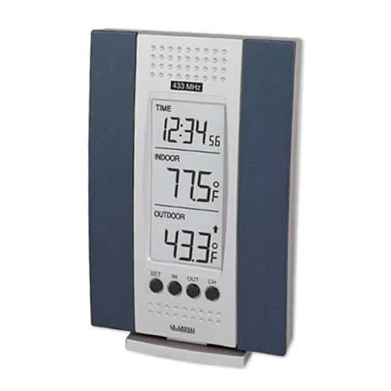
- Page 1 WS-7016U Wireless 433 MHz Temperature Station Instruction Manual...
-
Page 2: Table Of Contents
TABLE OF CONTENTS Topic Page Inventory of Contents Additional Equipment Quick Setup Detailed Setup Guide Battery Installation Remote Control Sender Indoor Temperature Station Setting the Time Selecting Units of Measurement Features Indoor Minimum and Maximum Temperatures Outdoor Minimum and 10-11 Maximum Temperatures Resetting the Indoor Minimum 11-12... - Page 3 Remote Control Sender 13-16 Indoor Temperature Station 16-18 Using Multiple Remote Control Senders Setup of Multiple Units 18-21 Viewing Remote Control 21-22 Senders Features of the Multiple Remote 22-23 Control Senders 24-28 Troubleshooting Maintenance and Care Instructions 28-29 29-31 Specifications 31-33 Warranty Information FCC DISCLAIMER...
-
Page 4: Inventory Of Contents
INVENTORY OF CONTENTS 1. The Indoor Temperature Station (Figure 1) 2. The Outdoor Remote Control Sensor (TX3U) and mounting bracket. (Figure 2) 3. 3 each, 1/2” Philips screws. 4. One strip of double sided adhesive tape. 5. Instruction Manual and Warranty Card. Figure 1 Figure 2 ADDITIONAL EQUIPMENT (not included) -
Page 5: Quick Setup
QUICK SETUP 1. Insert two AAA batteries into the Remote Control Sender. 2. Insert two AA batteries into the Indoor Temperature Station. 3. Wait 5-6 minutes, or until the outdoor temperature is displayed in the OUTDOOR LCD (Liquid Crystal Display) of the Indoor Temperature Station. -
Page 6: Detailed Setup Guide
DETAILED SETUP GUIDE BATTERY INSTALLATION A. REMOTE CONTROL SENDER Battery cover Battery compartment 1. Remove the mounting bracket. The bracket snaps on and off with minimal effort. 2. Remove battery cover. To do this, remove the flathead screw located in the lower-central position of the unit. - Page 7 battery cover to fall away from the unit. Place the screw partially back into the hole and angle it slightly, so the threads grab the battery cover. With the screw, pull the battery cover off. 3. Observing the correct polarity, install 2 AAA batteries.
-
Page 8: Indoor Temperature Station
B. INDOOR TEMPERATURE STATION Note: After the batteries are installed, DO NOT press any buttons. This may interfere with the signals, causing temperatures to register incorrectly. 1. Remove the battery cover on the backside. To do this, push up and pull out. - Page 9 2. Observing the correct polarity, install 2 AA batteries. 3. Replace battery cover. 4. Wait 5-6 minutes or until both indoor and outdoor temperatures shown Indoor Temperature Station. 5. The Indoor Temperature Station should now show: “-:- -” in the TIME LCD, and temperatures in the INDOOR and OUTDOOR LCD’s.
-
Page 10: Setting The Time
II. TIME Control Buttons A. SETTING THE TIME 1. Press and hold the SET button for 1 second. “12h” will appear in the TIME LCD. 2. Use the INDOOR button to select either 12h time or 24h time (12h is an AM—PM mode, and 24h is military time). -
Page 11: Selecting Units Of Measurement
5. Press the SET button to activate the clock. Note: There is only a “PM” display, which appears under “TIME.” If there is no display here it is AM. Make sure you set the time accordingly. III. UNITS OF TEMERATURE MEASURE A. -
Page 12: Features
IV. FEATURES A. INDOOR MINIMUM AND MAXIMUM TEMPERATURES 1. Press and hold the INDOOR button for 1 second. “MIN” appears in the INDOOR LCD and recorded minimum temperature is displayed. 2. Press and hold the INDOOR button for 1 second. “MAX”... -
Page 13: Outdoor Minimum And
B. OUTDOOR MINIMUM AND MAXIMUM TEMPERATURES 1. Press and hold the OUTDOOR button for 1 second. “MIN” appears in the OUTDOOR LCD. The “OUTDOOR MIN,” and “TIME” displays will flash. The recorded minimum temperature is displayed in the OUTDOOR LCD, and the time it was recorded is displayed in the TIME LCD. - Page 14 displayed in the OUTDOOR LCD, and the time it was recorded is displayed in the TIME LCD. After 15 seconds the “OUTDOOR MAX,” and “TIME” will stop flashing, maximum outdoor temperature will continue to be displayed. 3. To return to current temperature, press and hold the OUTDOOR button for 1 second.
- Page 15 temperatures are reset release the buttons. 2. To return to the current indoor temperature, press and hold the INDOOR button times, holding for 1 second each. B. OUTDOOR 1. To reset both the minimum and maximum temperatures—press continue hold OUTDOOR button, while you press and hold the RESET button.
-
Page 16: Reading The Temperature Trend
VI. READING THE TEMPERATURE TREND A. The temperature trend indicator is displayed in the OUTDOOR LCD. Indicates that the temperature is rising. Indicates that the temperature is dropping. 3. The absence of an arrow indicates that the temperature is stable. VII. -
Page 17: Remote Control Sender
walls, concrete, and large metal objects can reduce the range. Place both units in their desired location before permanently mounting the Remote Control Sender. There should be a change of temperature in the OUTDOOR LCD within 6 minutes. The Remote Control Sender can be mounted in two ways: •... - Page 18 c) Where marked, drill holes into mounting surface using an appropriate size drill bit. d) Screw mounting bracket onto the mounting surface. Ensure that the screws are flush with the bracket. 2. MOUNTING WITH ADHESIVE TAPE a) With a nonabrasive solution, clean and dry the back of the mounting bracket and the mounting surface to ensure a...
-
Page 19: Indoor Temperature Station
c) Remove the protective strip from the other side of the tape. Position the Remote Control Sender in the desired location, ensuring that the Indoor Temperature Station can receive the signal. B. THE INDOOR TEMPERATURE STATION Note: Before mounting the Indoor Temperature Station make sure that it is able to receive signals from the Remote Control Sender. -
Page 20: Wall Mounting
1. USING THE TABLE-STAND a) The Indoor Temperature Station comes with the table stand already mounted. you wish to use the table- stand all that is required is to place the Indoor Temperature Station in an appropriate location. 2. WALL MOUNTING... - Page 21 Gently pull the Station down to lock the screw into place. VIII. USING MULTIPLE REMOTE CONTROL SENDERS Your WS-7016U Indoor Temperature Station can receive signals from five different Remote Control Senders (The TX3U features temperature data transmission and the TX3UP...
- Page 22 offers the same plus a 10’ probe to insert in a pool, spa, soil, etc.). Assign a number to each Remote Control Sender (i.e. #1 will be for outdoors, #2 will be for the basement, etc.). This will help determine which temperature, from which Sender, you are reading on the Indoor Temperature Station.
-
Page 23: Setup Of Multiple Units
A. SETUP OF MULTIPLE UNITS 1. It is necessary to remove the batteries from all existing units in operation. 2. Remove the battery covers to all Remote Control Senders. section I.A.2. 3. Place all Remote Control Senders in sequential order. 4. - Page 24 5. Install batteries into the Indoor Temperature Station. (Refer to instructions in I.B.). 6. Follow directions in section II.A to set the time, section III.A to select Fahrenheit or Celsius, and section VII. A to mount. B. VIEWING MULTIPLE REMOTE CONTROL SENDERS ON THE INDOOR TEMPERATURE STATION...
- Page 25 3. Repeat step 1 to view the 3 and 5 (depending on how many are set up) temperatures sent by Remote Control Senders. Continue to press RESET until you return to the first Remote Control Sender. C. VIEWING THE FEATURES OF MULTIPLE REMOTE CONTROL SENDERS 1.
- Page 26 their minimum and maximum temperatures. 3. To reset OUTDOOR MINIMUM AND MAXIMUM TEMPERATURES, follow step 1 above directions sections V.A. through V.B. This will reset the minimum and maximum for only the selected Remote Control Sender.
-
Page 27: Troubleshooting
TROUBLESHOOTING Problem Solution Batteries may be inserted wrong “--. -” appears in Remote Control Sender— in the correct the polarity OUTDOOR LCD of the Indoor Temperature Station. The batteries may be weak— replace with new batteries. The Remote Control Sender may be out of its 80 foot (25m) range—bring the units closer together. - Page 28 Obstacles such walls, “--.-” appears in concrete, metal window the OUTDOOR frames, or large metal objects, LCD of the obstructing signal Indoor transmission from the Remote Temperature Control Sender—Relocate the Station. Remote Control Sender, within (continued) range, where there are no obstructions.
- Page 29 Control Sender. with new batteries. Remote Control Sender out of its 80 foot (25m) range—bring the units closer together. If problem persists contact La Crosse Technology for replacement. The LCD of the Check proper battery Indoor installation.
- Page 30 “incorrect” depending on the location of the Remote Control Sender. thermometers 100% accurate (the WS-7016U is accurate to +/- 2 °F). If you are sure the temperature is wrong (the unit reads 110 °F, when it is actually 70 °F) reset...
-
Page 31: Maintenance And Care Instructions
Problem not Call La Crosse Technology to covered under order replacement part. the warranty (ie. will accept Visa, MasterCard, Dropped unit Discover, or prepayments by into water). check. MAINTENANCE AND CARE INSTRUCTIONS • Extreme temperatures, vibration, and shock should be avoided to prevent damage to the units. -
Page 32: Specifications
• Opening casings invalidates warranty. Do not try to repair the unit. Contact La Crosse Technology repairs. SPECIFICATIONS Transmitting Frequency 433MHz Recommended Operating Temperature 32 °F to 122 °F Indoor Temperature Station (0 °C to 50 °C) 14 °F to 140 °F Remote Control Sender (-10 °C to 60 °C) - Page 33 -21.8 °F to 156.2 °F Remote Control Sender with 0.2 °F resolution. (-29.9 °C to 69.0 °C with 0.1 °C resolution). Accuracy +/- 2 °F (+/- 1 °C). Indoor +/- 2 °F (+/- 1 °C). Outdoor Transmitting range of Maximum feet (25m).
- Page 34 Battery life expectancy Approximately 1 year. for both units Dimensions: (L x W x H) Indoor Temperature 3.51 x 1.19 x 4.88 in. Station (excluding table stand) (90 x 30.5 x 125 mm). Remote Control Sender 2.18 x 0.94 x 3.12 in. (56 x 24 x 80 mm).
-
Page 35: Warranty Information
WARRANTY INFORMATION La Crosse Technology provides a 1- year warranty on this weather station. This warranty covers any defects due to faulty workmanship or materials. Contact La Crosse Technology immediately upon discovery of any defects covered by this warranty. Before sending the Weather Station in for repairs, contact La Crosse Technology. - Page 36 For warranty work, technical support, or information contact La Crosse Technology at: La Crosse Technology 190 Main Street La Crescent, MN 55947 Phone: (507) 895-7095 Fax: (507) 895-8000 e-mail: support@lacrossetechnology.com...
-
Page 37: Fcc Disclaimer
Operation is subject to the following two conditions: (1) this device may not cause harmful interference, and (2) this device must accept any interference received, including interference that may cause undesired operation. Freq. 433.92 MHz La Crosse Technology Made in China WS7016U...