Yamaha CDC-697 Service Manual
Hide thumbs
Also See for CDC-697:
- Owner's manual (178 pages) ,
- Owner's manual (33 pages) ,
- Owner's manual (78 pages)
Table of Contents
Advertisement
This manual has been provided for the use of authorized YAMAHA Retailers and their service personnel.
It has been assumed that basic service procedures inherent to the industry, and more specifically YAMAHA Products, are already
known and understood by the users, and have therefore not been restated.
WARNING:
IMPORTANT:
The data provided is believed to be accurate and applicable to the unit(s) indicated on the cover. The research, engineering, and
service departments of YAMAHA are continually striving to improve YAMAHA products. Modifications are, therefore, inevitable
and specifications are subject to change without notice or obligation to retrofit. Should any discrepancy appear to exist, please
contact the distributor's Service Division.
WARNING:
IMPORTANT:
I CONTENTS
TO SERVICE PERSONNEL ...................................... 2-3
FRONT PANEL .............................................................. 4
REAR PANELS .......................................................... 5-6
REMOTE CONTROL PANEL ........................................ 6
SPECIFICATIONS .......................................................... 7
INTERNAL VIEW ........................................................... 7
DISASSEMBLY PROCEDURES ............................. 8-10
STANDARD OPERATION CHART ....................... 11-12
TEST MODE ........................................................... 13-15
1 0 1 0 3 0
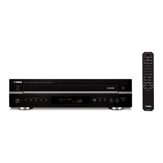
COMPACT DISC PLAYER
CDC-697
SERVICE MANUAL
IMPORTANT NOTICE
Failure to follow appropriate service and safety procedures when servicing this product may result in personal
injury, destruction of expensive components, and failure of the product to perform as specified. For these reasons,
we advise all YAMAHA product owners that any service required should be performed by an authorized
YAMAHA Retailer or the appointed service representative.
The presentation or sale of this manual to any individual or firm does not constitute authorization, certification or
recognition of any applicable technical capabilities, or establish a principle-agent relationship of any form.
Static discharges can destroy expensive components. Discharge any static electricity your body may have
accumulated by grounding yourself to the ground buss in the unit (heavy gauge black wires connect to this buss).
Turn the unit OFF during disassembly and part replacement. Recheck all work before you apply power to the unit.
ERROR MESSAGES ............................................. 16-18
IC DATA ................................................................. 19-24
DISPLAY DATA ........................................................... 25
PIN CONNECTION DIAGRAMS .................................. 26
BLOCK DIAGRAM ....................................................... 27
PRINTED CIRCUIT BOARDS................................ 28-33
SCHEMATIC DIAGRAMS ...................................... 35-36
REPLACEMENT PARTS LIST .............................. 37-44
REMOTE CONTROL .................................................... 45
Parts List for Carbon Resistors ................................ 46
2006
All rights reserved.
This manual is copyrighted by YAMAHA and may not be copied or
redistributed either in print or electronically without permission.
P.O.Box 1, Hamamatsu, Japan
'06.09
Advertisement
Table of Contents

Related Manuals for Yamaha CDC-697


Summary of Contents for Yamaha CDC-697
-
Page 1: Table Of Contents
This manual has been provided for the use of authorized YAMAHA Retailers and their service personnel. It has been assumed that basic service procedures inherent to the industry, and more specifically YAMAHA Products, are already known and understood by the users, and have therefore not been restated. -
Page 2: To Service Personnel
CDC-697 I TO SERVICE PERSONNEL AC LEAKAGE TESTER OR 1. Critical Components Information WALL EQUIPMENT EQUIVALENT OUTLET UNDER TEST Components having special characteristics are marked Z and must be replaced with parts having specifications equal to those originally installed. 2. Leakage Current Measurement (For 120V Models Only) -
Page 3: Protection Of Eyes From Laser Beam During Servicing
CDC-697 PROTECTION OF EYES FROM LASER BEAM DURING SERVICING This set employs a laser. Therefore, be sure to care- fully follow the instructions below when servicing. 1. Laser Diode Properties • Material : GaAlAs • Wavelength : 790 nm • Emission Duration : Continuous •... -
Page 4: Prevention Of Electrostatic Discharge
2. The flexible cable lines may break if an excessive force is applied to it. Use caution when handling the cable. 3. The semi-fixed resistor for laser power adjustment should not be adjusted. Do not turn the resistor. I FRONT PANEL CDC-697 (U, C, R, T, A, B, G, L models) -
Page 5: Rear Panels
CDC-697 I REAR PANELS CDC-697 (U, C models) CDC-697 (R model) CDC-697 (T model) CDC-697 (A model) -
Page 6: Remote Control Panel
CDC-697 CDC-697 (B, G models) CDC-697 (L model) I REMOTE CONTROL PANEL... -
Page 7: Specifications
CDC-697 I SPECIFICATIONS I INTERNAL VIEW I Audio Section Output Level (1 kHz, 0 dB) ..........2 ±0.5 V MAIN (7) P.C.B. (U, C, A, B, G models) Signal to Noise Ratio ..........106 dB or more MAIN (2) P.C.B. (R, L models) Dynamic Range ............ -
Page 8: Disassembly Procedures
CDC-697 I DISASSEMBLY PROCEDURES (Remove parts in the order as numbered.) Removal of Top Cover • Precaution for installation of the Tray Ass’y. Remove 4 screws (1) and 3 screws (2). (Fig. 1) On tray ass’y setting. Lift the top cover at the rear and move it rearward Check the direction of marking “... - Page 9 CDC-697 CM-230A unit can not be removed without removing Removal of PU Mechanism Unit the Front Panel Unit. Remove 2 screws (A) and then remove the PU unit ass’y. (Fig. 6) 5-A. Removal of Front Panel Unit Remove CB200 and CB304. (Fig. 4)
-
Page 10: Rear Panels
CDC-697 • When checking the P.C.B.: Remove the top cover. Remove the tray ass’y. Remove 3 screws (1) and 2 jack screws (2). (Fig. 1) Remove 1 screw (3), 1 screw (4) and 1 push rivet. (Fig. 2) Spread a cloth over the main chassis. (Fig. 2) Put the MAIN (1) and MAIN (6) P.C.B.s on end. -
Page 11: Standard Operation Chart
CDC-697 I STANDARD OPERATION CHART Press "OPEN/CLOSE" key. "OPEN" is displayed. TRV signal is output until detection of FEED LIMIT switch. Forced feed return operation. Proceeds to next step after detection of CLAMP switch. (SW401) Clamp down operation. Disc table reset. - Page 12 CDC-697 Focus gain adjustment. Tracking gain adjustment. *TOC READ * ~ Data fetch cycle ~ Track No. "1" is searched. : MUTE OFF = "L" → "H", "0:00" is displayed. After searching the beginning, Mute is cancelled. (IC309, pin 28) ~ PLAY ~ Set to search by means of "Y", "T"...
-
Page 13: Test Mode
CDC-697 I TEST MODE • Starting TEST mode Test mode is started when the power is turned on while the “PLAY/PAUSE” and “STOP” keys on the panel are simultaneously pressed and held. When the test mode is started, as shown below is displayed. - Page 14 CDC-697 • Function List of Remote Control Transmitter CUSTOM CODE = (79)x Code Function MODE Traverse stop. OPEN/CLOSE Tray open/close. PLAY PLAY (FOON, TRON, TVON (FEON), SPON) SKIP Backward traverse move. (If inner SW turns on, traverse is stopped.) (Coefficient set up mode: upper digit down.) SEARCH Clamp down.
- Page 15 CDC-697 (Note 2) Checks FL display. DIMMER TEXT/TIME...
-
Page 16: Test Mode
CDC-697 I ERROR MESSAGES When stopped by any cause, press “STOP” key of the remote control while pressing and holding the “STOP” key on the main unit. The operation mode turns to the mode allowing the display of messages. The unit hold the latest error message in microprocessor. So even if stopped with no error, the unit can display the latest error massage with same operation. - Page 17 CDC-697 Error code x8 ........Focus drops. 2) Troubleshooting from system malfunc- tions. a) Tray fails to come out/go in. Is disc dirty or Check by using another disc. scratched? Poor mechanism operation. Tray starts to Wire caught. move but stops.
- Page 18 CDC-697 c) Operates as if no disc loaded. d) Sound skips. (although loaded) (Time display fails to advance properly) Is disc dirty, Does table Check by using a Poor table rotation. scratched or rotate properly? known good disc. warped? Infrared sensor defective.
-
Page 19: Ic Data
CDC-697 I IC DATA : MN35511AL (MAIN P.C.B.) Signal processor and controller 58 59 56 19 49 8 7 9 44 46 45 47 48 52 53 67 62 15 14 68 73 72 74 75 13 55 78 80 79... - Page 20 CDC-697 Pin no. Name Function BCLK Bit clock output for SR DATA LRCK L/R identification signal output SRDATA Serial data output DVDD1 Power supply for digital circuit (+5) DVSS1 GND for digital circuit Digital, audio, interface output signal MCLK Microprocessor command clock signal input (data latched at leading edge)
- Page 21 CDC-697 Pin no. Name Function AVSS2 GND for analog circuit (for AD of DSL, PLL, DA output blocks) (GND) EFM signal output (NC) PCK/ With command defaulted: PLL extract clock output PCK when IOSEL=H, frame re- RESY synchronous signal RESY when IOSEL=L These settings can be reversed by command (RESY when IOSEL=H).
- Page 22 CDC-697 IC309 : µPD78F0546 (MAIN P.C.B.) Microprocessor * No replacement part available. 16-bit timer/ TO00/TI010/P01 event counter 00 TI000/P00 Port 0 P00 to P06 RxD6/P14(LINSEL) TO01/TI011/P06 16-bit timer/ Port 1 P10 to P17 event counter 01 TI001/P05 Port 2 P20 to P27...
- Page 23 CDC-697 Pin function Function Signal name Detail of function Port type P120/INTP0/EXLVI INTP0 Remote control signal input CMOS OPSW Tray OPEN SW CMOS CLSW Tray CLOSE SW CMOS TBL_POS Table position CMOS /RST MN35511 system reset L: reset CMOS DMUTE...
- Page 24 CDC-697 Pin function Function Signal name Detail of function Port type ANI7/P27 ANI7 /PDN Power down detect CMOS ANI6/P26 ANI6 KEY1 Front Panel Key A/D 1 CMOS ANI5/P25 ANI5 KEY0 Front Panel Key A/D 0 CMOS ANI4/P24 CMOS ANI3/P23 CLOSE...
-
Page 25: Display Data
CDC-697 I DISPLAY DATA G V300 : 15-ST-54GN (WH406200) G ANODE CONNECTION 15G-4G PATTERN AREA G PIN CONNECTION Pin No. Connection Pin No. Connection – Pin No. – – – Connection – – Pin No. – – Connection – –... -
Page 26: Pin Connection Diagrams
CDC-697 I PIN CONNECTION DIAGRAMS • ICs • Transistors 2SA1708 2SA933S 2SB544 2SC1740S RSR025N03 ADM202JRN-REEL7 AN4801SB AN8882SB BD4243G-TR RST025P03TL Drain Source Gate 2SD2394 2SD1915F BR24L01AF-WE2 KIA7805API KIA79S05P-AT M66003-0131FP MN35511AL KIA7812API COMMON INPUT OUTPUT µPD78F0546 NJM2068D-D NJM78M05FA LB6510 3: OUT 1: IN 2: GND •... -
Page 27: Block Diagram
CDC-697 I BLOCK DIAGRAM AUDIO SECTION BLOCK DIAGRAM CM-230A UNIT PU UNIT ASS'Y L.P.F. IC101 IC101 OUT L Q101 Q103 HEAD LINE OUT L.P.F. CONTROL IC102 Q102 Q104 IC102 AN8882SB OUT R LASER LD ON MN35511 MUTE VREF CONTROL IC307... -
Page 28: Printed Circuit Boards
CDC-697 I PRINTED CIRCUIT BOARDS MGND VCC+B D4GND MAIN (1) P.C.B. (Side A) VCCD5+5 TBL_L TBL_R CL_DOWN CM (4) CL_UP (CB408) CLOSE OPEN OPSW CLSW PU MECHANISM UNIT DOWNSW UPSW TBL_POS PU MECHANISM UNIT MAIN (8) (CB202) • Semiconductor Location Ref no. - Page 29 CDC-697 MAIN (1) P.C.B. (Side B) No replacement part available. 32 33 60 61 • Semiconductor Location Ref no. Location IC302 IC306 IC309 Q208 Q209 Q210...
- Page 30 CDC-697 MAIN (2) P.C.B. (Side A) R, L models MAIN (3) P.C.B. (Side A) VOLTAGE SELECTOR AC 110V/120V/220V/230-240V VCCD+5 KEY0 FLGND MAIN (4) (CB05) DISC5 DISC4 DISC2 DISC1 DISC3 STANDBY/ON • Semiconductor Location MAIN (8) MAIN (8) Ref no. Location...
- Page 31 CDC-697 MAIN (4) P.C.B. (Side A) MAIN (1) (CB304) • Semiconductor Location Ref no. Location D308 D309 D310 D311 D312 OPEN/CLOSE IC303 MAIN (3) (CB306) VCCD+5 KEY0 FLGND STOP PLAY/PAUSE PLAYXCHANGE MAIN (4) P.C.B. (Side B) 48 49...
- Page 32 CDC-697 MAIN (7) P.C.B. (Side A) U, C, A, B, G models AC IN Circuit No. U, C B, G J123 J124 J126 X : NOT USED O : USED/APPLICABLE MAIN (8) P.C.B. (Side A) MAIN (2) (W205B) /PDN D4GND...
- Page 33 CDC-697 CM (1) P.C.B. CM (4) P.C.B. (Side A) (Side A) LOADING MOTOR TABLE SENSOR DISC CLAMP MOTOR TRAY ROTATE MOTOR TBL_L TBL_R CL_DOWN CL_UP CLOSE OPEN OPSW CL_SW CM (2) P.C.B. DOWN_SW (Side A) UPSW TBL_POS MAIN (1) CLAMP UP/DOWN SW...
- Page 34 CDC-697 MEMO MEMO MEMO MEMO...
-
Page 35: Schematic Diagrams
CDC-697 SCHEMATIC DIAGRAMS MAIN IC1: AN8882SB MAIN (1) MAIN (6) CD-ROM drive head amplifier HEAD AMP RF AGC detection amp. EQCTL CBDO RFDET amp. COFTR OFTR OFTR -5.2 amp. -13.2 To PU mechanism unit FEOUT amp. REF2 LINE OUT L/R REF2 Amp. -
Page 36: Schematic Diagrams
CDC-697 IC401: LA6510 CM (4) 1A power operational amplifier CM (1) VSENSE1 VOUT1 VIN1- VIN1+ VIN2+ VIN2- CM (2) CLAMP-UP/DOWN SW VOUT2 TABLE SENSOR VSENSE2 Page 35 CM (3) to MAIN (1)_CB300 LOADING SW IC402: TA7291P Bridge driver Vref -13.3... -
Page 37: Replacement Parts List
CDC-697 I REPLACEMENT PARTS LIST • ELECTRICAL COMPONENT PARTS WARNING G Components having special characteristics are marked s and must be replaced with parts having specifications equal to those originally installed. ABBREVIATIONS IN THIS LIST ARE AS FOLLOWS: C.A.EL.CHP : CHIP ALUMI.ELECTROLYTIC CAP L.EMIT... - Page 38 CDC-697 P.C.B. MAIN Ref. No. Part No. Description Markets Ref. No. Part No. Description Markets WH461400 P.C.B. MAIN C47-50 UR866100 C.EL WH461500 P.C.B. MAIN UR818470 C.EL 470uF 6.3V WH461700 P.C.B. MAIN C52-54 VJ599100 C.CE.TUBLR 0.1uF WH461600 P.C.B. MAIN C101 UA652100 C.MYLAR...
- Page 39 CDC-697 P.C.B. MAIN and P.C.B. CM Ref. No. Part No. Description Markets Ref. No. Part No. Description Markets D212 VG437700 DIODE.ZENR MTZJ5.6B 5.6V V3393500 SHEET.FL D214 VG443300 DIODE.ZENR MTZJ30B V3747500 SUPRT D217 VS997800 DIODE WE774000 SCR.BND.HD 3x6 MFZN2W3 D308 V2598200 LED SIR-505ST WH526300 SPACER.FL 6x12 t=4...
- Page 40 CDC-697 • OVERALL ASS’Y R, T, L models R, L models 10 (7) 200-1 5-10 6-10 PU unit ass'y 5-10 5-10 CM-230A unit 10 (5) 3-30 3-13 10 (3) 3-14 3-30 10 (4) 3-17 3-30 10 (6) 3-11 3-12 3-16...
- Page 41 CDC-697 Ref. No. Part No. Description Remarks Markets Ref. No. Part No. Description Remarks Markets MF118200 FLEXIBLE FLAT CABLE 18P 200mm P=1.25 VQ780300 D60xH16 3-11 WH256600 FRONT PANEL WH256800 LID CDC 3-11 WH256700 FRONT PANEL WH256900 LID CDC 3-12 WH267500...
- Page 42 CDC-697 • CM-230A UNIT Ref. No. Part No. Description Remarks Markets CM-230A UNIT WH462300 P.C.B. ASS'Y V6660800 FERRITE CORE F5 T19x10x10 WH954100 FLEXIBLE FLAT CABLE 17P 110mm P=1.25 V3175700 CONNECTOR ASS'Y 3P 220mm V3175900 CONNECTOR ASS'Y 3P 220mm MF706450 IDC CABLE ASS'Y 6P 450mm C&C...
- Page 43 CDC-697 • PA UNIT ASS'Y Note : Neither the pick-up head nor the spindle motor is available independently because they are factory-adjusted for the optimum level after assembly. If the pick-up head or the spindle motor must be replaced, be sure to replace them together as a unit.
- Page 44 CDC-697 • GREASE APPLICATION DIAGRAM Apply the grease Molykote PG-663 (Part No. AAX01170) PG-663 PU MECHANISM UNIT PG-663 PG-663 PG-663...
-
Page 45: Remote Control
CDC-697 I REMOTE CONTROL • PANELS • SCHEMATIC DIAGRAM 3.3 ohms IR-LED RT83P02 2SD1781K 220 ohms XOUT 15pF 4MHz 15pF • KEY LAYOUT VPP_RSB • KEY CODE Key No. Function Custom Data Key No. Function Custom Data STANDBY/ON SYNCHRO DIMMER... -
Page 46: Parts List For Carbon Resistors
CDC-697 Parts List for Carbon Resistors Value 1/4W Type Part No. 1/6W Type Part No. Value 1/4W Type Part No. 1/6W Type Part No. 1.0 Ω 3100 3100 10 kΩ 7100 7100 HJ35 HF85 HF45 HF45 1.8 Ω ❊ 3180 11 kΩ...