Yamaha CD-S700 Service Manual
Hide thumbs
Also See for CD-S700:
- Owner's manual (180 pages) ,
- Owner's manual (29 pages) ,
- Owner's manual (26 pages)
Table of Contents
Advertisement
This manual has been provided for the use of authorized YAMAHA Retailers and their service personnel.
It has been assumed that basic service procedures inherent to the industry, and more specifi cally YAMAHA Products, are already known
and understood by the users, and have therefore not been restated.
WARNING:
IMPORTANT:
The data provided is believed to be accurate and applicable to the unit(s) indicated on the cover. The research, engineering, and service
departments of YAMAHA are continually striving to improve YAMAHA products. Modifications are, therefore, inevitable and
specifi cations are subject to change without notice or obligation to retrofi t. Should any discrepancy appear to exist, please contact the
distributor's Service Division.
WARNING:
IMPORTANT:
■ CONTENTS
TO SERVICE PERSONNEL ........................................2-4
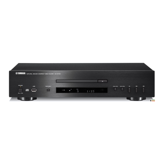
FRONT PANEL ...............................................................6
REAR PANELS ...........................................................6-8
REMOTE CONTROL PANEL ..........................................8
SPECIFICATIONS / 参考仕様 .........................................9
INTERNAL VIEW .......................................................... 10
DISASSEMBLY PROCEDURES / 分解手順 ........... 11-13
TEST MODE / テストモード ................................... 14-15
UPDATING FIRMWARE /
ファームウェアの書き込み ..................................... 16-20
1 0 1 1 1 8
COMPACT DISC PLAYER
CD-S700
SERVICE MANUAL
IMPORTANT NOTICE
Failure to follow appropriate service and safety procedures when servicing this product may result in personal injury,
destruction of expensive components, and failure of the product to perform as specifi ed. For these reasons, we advise
all YAMAHA product owners that any service required should be performed by an authorized YAMAHA Retailer or
the appointed service representative.
The presentation or sale of this manual to any individual or fi rm does not constitute authorization, certifi cation or
recognition of any applicable technical capabilities, or establish a principle-agent relationship of any form.
Static discharges can destroy expensive components. Discharge any static electricity your body may have
accumulated by grounding yourself to the ground buss in the unit (heavy gauge black wires connect to this buss).
Turn the unit OFF during disassembly and part replacement. Recheck all work before you apply power to the unit.
IC DATA ...................................................................21-26
DISPLAY DATA .............................................................27
PIN CONNECTION DIAGRAMS ...................................28
BLOCK DIAGRAM ........................................................29
PRINTED CIRCUIT BOARDS .................................30-38
SCHEMATIC DIAGRAMS .......................................39-42
REPLACEMENT PARTS LIST ................................43-53
REMOTE CONTROL ...............................................54-55
Copyright © 2008
This manual is copyrighted by YAMAHA and may not be copied or
redistributed either in print or electronically without permission.
All rights reserved.
P.O.Box 1, Hamamatsu, Japan
animate '08.10
Advertisement
Table of Contents

Related Manuals for Yamaha CD-S700


Summary of Contents for Yamaha CD-S700
-
Page 1: Table Of Contents
This manual has been provided for the use of authorized YAMAHA Retailers and their service personnel. It has been assumed that basic service procedures inherent to the industry, and more specifi cally YAMAHA Products, are already known and understood by the users, and have therefore not been restated. -
Page 2: To Service Personnel
CD-S700 ■ TO SERVICE PERSONNEL AC LEAKAGE 1. Critical Components Information WALL EQUIPMENT TESTER OR Components having special characteristics are marked OUTLET UNDER TEST EQUIVALENT must be replaced with parts having specifications equal to those originally installed. 2. Leakage Current Measurement (For 120V Models Only) - Page 3 CD-S700 WARNING: Laser Safety 警告:レーザーの安全対策 This product contains a laser beam component. This 本機はレーザー光線を放射する部品を搭載しています。 component may emit invisible, as well as visible radi- この部品が放射するレーザー光線は目に損傷を起こしま ation, which may cause eye damage. To protect your す。このレーザー光線から目及び肌を保護するために、 eyes and skin from laser radiation, the following pre- 本機の修理作業中は下記の注意を厳守してください。...
- Page 4 CD-S700 Warning for power supply The primary side of the power supply carries live mains voltage when the player is connected to the mains even when the player is switched off ! This primary area is not shielded so it is possible to accidentally touch copper tracks and/or components when servicing the player.
-
Page 5: Prevention Of Electrostatic Discharge
CD-S700 ■ PREVENTION OF ELECTROSTATIC DISCHARGE Some semiconductor (solid state) devices can be damaged easily by static electricity. Such components commonly are called Electrostatically Sensitive (ES) Devices. Examples of typical ES devices are integrated circuits and some field-effect transistors and semiconductor “chip” components. The following techniques should be used to help reduce the incidence of component damage caused by electro static discharge (ESD). -
Page 6: Front Panel
CD-S700 ■ FRONT PANEL CD-S700 (U, R, T, K, A, B, G, L, J models) ■ REAR PANELS CD-S700 (U model) CD-S700 (R model) CD-S700 (T model) - Page 7 CD-S700 CD-S700 (K model) CD-S700 (A model) CD-S700 (B, G models) CD-S700 (L model)
-
Page 8: Remote Control Panel
CD-S700 CD-S700 (J model) ■ REMOTE CONTROL PANEL CDX-7... -
Page 9: Specifications / 参考仕様
CD-S700 ■ SPECIFICATIONS / 参考仕様 ■ Audio Section / オーディオ部 Dimensions (W x H x D) / 寸法(幅 × 高さ × 奥行き) Output Level / 出力レベル (1 kHz, 0 dB) ....435 x 96 x 300 mm (17-1/8" x 3-3/4" x 11-3/4") ................. -
Page 10: Internal View
CD-S700 ■ INTERNAL VIEW OPERATION (5) P.C.B. OPERATION (7) P.C.B. (R, L models) DIGITAL P.C.B. OPERATION (3) P.C.B. OPERATION (9) P.C.B. Loader Mechanism Ass'y OPERATION (4) P.C.B. OPERATION (8) P.C.B. OPERATION (6) P.C.B. OPERATION (2) P.C.B. OPERATION (1) P.C.B. -
Page 11: Disassembly Procedures / 分解手順
CD-S700 ■ DISASSEMBLY PROCEDURES / 分解手順 (Remove parts in the order as numbered.) (番号順に部品を取り外してください。 ) Disconnect the power cable from the AC outlet. AC 電源コンセントから、電源コードを抜いてください。 1. Removal of Top Cover 1. トップカバーの外し方 a. Remove 4 screws ( ) and 4 screws ( ). - Page 12 CD-S700 2. Removal of Front Panel Ass’y 2. フロントパネル ASSY の外し方 a. Using a flatblade screwdriver, move the slider at the a. マイナスドライバーで底面のスライダーを下図の矢印 bottom in the direction of the arrow shown below. (Fig. 2) の方向に動かします。 (Fig. 2) The disc tray lock will be released but will not ※...
- Page 13 CD-S700 3. Removal of Loader Mechanism Ass’y 3. ローダーメカ ASSY の外し方 a. Remove 4 screws ( ). (Fig. 4) a. ( ) のネジ 4 本を外します。 (Fig. 4) b. Remove CB153, CB302 and CB602. (Fig. 4) b. CB153、CB302、CB602 を外します。 (Fig. 4)...
-
Page 14: Test Mode / テストモード
CD-S700 ■ TEST MODE / テストモード Check the FL display and indicators for display/indication FL ディスプレイとインジケーターの表示状態をチェック condition. します。 ● Check the FL display and Indicators ● FL ディスプレイとインジケーターの確認 1. Press the “POWER ON/OFF” switch inward to the 1. 本機の下図に示す 3 つのキーを同時に押しながら... - Page 15 CD-S700 ● Operation Procedure of Test Mode ● テストモード時の操作 Function list of panel keys / テストモード時のパネルキー Panel key / パネルキー Function / 機能 Display / 表示 OPEN/CLOSE Disc tray open/close / ディスクトレイ オープン/クローズ OPEN / CLOSE PLAY Trace on / トレース オン...
-
Page 16: ファームウェアの書き込み
CD-S700 ■ UPDATING FIRMWARE / ファームウェアの書き込み After replacing the following parts update the latest firm- 下記の部品を交換した場合、下記の手順により最新の ware according to the following procedure. ファームウェアの書き込みを行ってください。 DIGITAL P.C.B. DIGITAL P.C.B. Microprocessor (IC304) of DIGITAL P.C.B. DIGITAL P.C.B. のマイコン(IC304) ● Required tools ● 必要なツール... - Page 17 CD-S700 ● Operation Procedures ● 操作手順 1. Connect the power cable of this unit to the AC 1. 本機の電源コードを AC コンセントに接続します。 outlet. 2. RS232C 変換冶具のリセットスイッチを押しなが 2. While pressing the reset switch of RS232C con- ら、本機の POWER ON/OFF スイッチを押して version jig, press the “POWER ON/OFF” switch of オンにします。...
- Page 18 CD-S700 5. Click [Refer...]. And select the firmware name. 5. [Refer...]をクリックし、書き込むファームウェア (Fig. 4) を選択します。 (Fig. 4) The ID code and MCU type are loaded auto- ※ ID、および MCU Type は書き込みファイル選 matically when the file is selected. (Fig. 4) 択時、自動的に取り込まれます。 (Fig. 4)...
- Page 19 CD-S700 7. When the program transmission is completed, the 7. プログラムの送信が終了すると、下記の画面が表 screen appears as shown below. (Fig. 6) 示されます。 (Fig. 6) Click [OK] to end the procedure. (Fig. 6) [OK]をクリックして完了します。 (Fig. 6) Fig. 6 8. Press the “POWER ON/OFF” switch of this unit to 8.
- Page 20 CD-S700 ● Confirmation of firmware version ● ファームウェアバージョンの確認 Press the “POWER ON/OFF” switch inward to the ON 本機の PLAY キーと STOP キーを押しながら、 position while simultaneously pressing the “PLAY” POWER ON/OFF スイッチを押してオンにし、これ and “STOP” keys of this unit, and then release these ら...
-
Page 21: Ic Data
CD-S700 ■ IC DATA IC304: M30302FAPFP (DIGITAL P.C.B.) Single-chip 16-bit microprocessor Port P0 Port P1 Port P2 Port P3 Port P4 Port P5 Port P6 Peripheral function System clock generator A/D converter Timer (16-bit) (10-bit 18-channel COUT Input (timer A) x3... - Page 22 CD-S700 Port Name Function Name Detail of Function P9_6/ANEX1 (No connected) CLAMP_SW2 P9_5/ANEX0 Clamp SW2 CLAMP_SW1 P9_4 Clamp SW1 TRAY_SW4 P9_3 TRAY_SW3 P9_2/TB2IN Tray SW3 / Loader mechanism specification confirm TRAY_SW2 P9_1/TB1IN Tray SW2 TRAY_SW1 P9_0/TB0IN Tray SW1 BYTE BYTE...
- Page 23 CD-S700 Port Name Function Name Detail of Function 61 FL_RES P3_1/A9 FL control 62 VCC2 VCC2 63 FL_CS P3_0/A8 FL control 64 VSS 65 USB_FLG P2_7/A7 (No connected) 66 USB_EN P2_6/A6 (No connected) 67 SYS_RICO_C P2_5/A5 (No connected) 68 SYS_RICO_U...
- Page 24 CD-S700 IC604: MN103SFB5KYAA (DIGITAL P.C.B.) USB microprocessor INTERFACE 32 bit MEMORY 256 KByte 8 KB FLASH MICRO- DMA 4 CH MEMORY PROCESSOR CORE DATA 8 KByte I/O port INTERRUPT TIMER 34 pcs (3 V type) CONTROL 8 pcs (5 V type)
- Page 25 CD-S700 Port Name Function Name Detail of Function N.C. USBNOC USB over-current input (negative polarity) USBNPP USB, VBUS power output control terminal (negative polarity) USBD- USB D- terminal AVSS Ground / Analog power supply for USB / Connect to VSS.
- Page 26 CD-S700 Port Name Function Name Detail of Function 50 N.C. N.C. 53 VSS Ground 54 STREQ PD5/IRQ2 External interrupt request signal input terminal 55 CS PD4/IRQ1 External interrupt request signal input terminal 56 N.C. 57 TX PD1/SBI2 Clock synchronization/start stop synchronization serial terminal...
-
Page 27: Display Data
CD-S700 ■ DISPLAY DATA ● V101 : 13-ST-81GINK (OPERATION (1) P.C.B.) ● PIN CONNECTION Pin No. Connection Q13G Pin No. Connection RESET Pin No. Connection LGND PGND Note: 1) F1, F2 ..Filament 2) NP ..No pin 3) NX ..No extended pin 4) DL .. -
Page 28: Pin Connection Diagrams
CD-S700 ■ PIN CONNECTION DIAGRAMS • ICs BD9870FPS-E2 BD4829G-TR DSD1791DBR LB1641 M12L16161A-7TG M30302FAPFP MN103SFB5KYAA OP275GSR PQ033ES3MXP R1172S331B-E2-F R5523N001A-TR-F RP131S501D-E2-F TC74VHCT08AFT TC7SH08F TC7WU04F TS7ST00F • Diodes D4SBN20-7101 RS203M-B-C-J80 1N4002S 1SS355 FM203-W TE MA-8039-H MA8047-H MA8056-M 5.6V Anode MA8062-M Anode MA8130-M MA8300-M 30.0V RB050LA-40TR TP –... -
Page 29: Block Diagram
CD-S700 ■ BLOCK DIAGRAM OPERATION D104 POWER Indicator SW101, SW102, U101 → CB161 V101 D102 PURE DIRECT Indicator SW105-107 Remote SCHEMATIC DIAGRAM USB Connector FL-Display D103 USB Indicator Front Panel Keys Front Panel → DIGITAL USB+5 IC606 FL_CLK/FL_Data SCHEMATIC DIAGRAM... -
Page 30: Printed Circuit Boards
CD-S700 ■ PRINTED CIRCUIT BOARDS • Semiconductor Location Ref no. Location Ref no. Location Ref no. Location Ref no. Location Ref no. Location DIGITAL P.C.B. (Side A) D300 D602 IC304 IC309 IC604 D302 D604 IC305 IC310 IC605 D303 IC300 IC306... - Page 31 CD-S700 DIGITAL P.C.B. (Side B) R 8 1 9 • Semiconductor Location Ref no. Location D304 D306 R 8 2 0 D307 D308 D310 D311 D312 D313 D314 D317 D603 Q300 Q601...
- Page 32 CD-S700 OPERATION (1) P.C.B. OPERATION (2) P.C.B. (Side A) (Side A) POWER indicator OPERATION (9) (CB152) OPEN/CLOSE CB101 W101A PURE DIRECT indicator STOP PAUSE PLAY indicator PURE DIRECT • Semiconductor Location Ref no. Location D102 D103 D104...
- Page 33 CD-S700 OPERATION (1) P.C.B. OPERATION (2) P.C.B. (Side B) (Side B) • Semiconductor Location Ref no. Location D101 IC802 Q101 Q102 Q103 Q104 Q105...
- Page 34 CD-S700 OPERATION (3) P.C.B. (Side A) AGND OPERATION (4) (CB206) DIGITAL (CB301) • Semiconductor Location Ref no. Location...
- Page 35 CD-S700 OPERATION (3) P.C.B. (Side B) • Semiconductor Location Ref no. Location...
- Page 36 CD-S700 OPERATION (4) P.C.B. (Side A) R, L models • Semiconductor Location Ref no. Location D204 D205 D211 D212 D213 W202B W204B W201B W203B D214 D215 Q201 W205B DGND T, K, J models MGND ACFL2 ACFL1 FLGND U, A, B, G models...
- Page 37 CD-S700 OPERATION (4) P.C.B. (Side B) • Semiconductor Location Ref no. Location D201 D206 OPERATION (5) P.C.B. (Side B) OPERATION (6) P.C.B. OPERATION (7) P.C.B. (Side B) (Side B)
- Page 38 CD-S700 OPERATION (8) P.C.B. OPERATION (8) P.C.B. (Side A) (Side B) CB161 CB162 DIGITAL (CB609) OPERATION (9) P.C.B. OPERATION (9) P.C.B. (Side A) (Side B) DIGITAL (CB303) FLGND FLGND ACFL2 ACFL1 LED_USB LED_PDIRECT +3.3 LED_POWER KEY0 KEY1 KEY2 FL_CS FL_DATA...
-
Page 39: Schematic Diagrams
CD-S700 SCHEMATIC DIAGRAMS DIGITAL 1/2 IC605 SDRAM CD CONTROLLER (Writing port) CB604 CD IN ACTUATOR DRIVER IC606 J 8 1 1 D 8 0 3 MICROPROCESSOR USB IN CB609 To Loader ass ’ CB602 Page 41 to OPERATION (8)_CB162 AUDIO OUT... - Page 40 CD-S700 DIGITAL 2/2 20.0 IC300 IC303 LEVEL SHIFTER IC308 IC308 CB303 IC308 20.0 IC302 IC308 Page 42 to OPERATION (9)_CB151 MICROPROCESSOR IC304 IC311 CB300 Page 42 IC311: RP131S501D-E2-F Voltage regulator to OPERATION (4)_W208 J 8 1 0 Vref Current Limit Pin No.
- Page 41 CD-S700 OPERATION 1/2 OPERATION (1) 30.3 30.3 30.3 CB101 OPERATION (2) W101A W101B POWER indicator OPERATION (8) CB161 CB162 Page 39 to DIGITAL_CB609 IC802 -11.6 -11.6 -11.6 -11.6 3 3 0 D/A CONVERTER s 1 6 1 0 0 / 5 0 11.5...
- Page 42 CD-S700 OPERATION 2/2 OPERATION (4) CB206 OPERATION (7) R, L models Page 41 to OPERATION (3)_CB1 10.0 20.0 s 1 6 I C 2 X V 7 6 3 A 0 Y A 0 8 9 A 0 Y A 0 8 9 A 0...
-
Page 43: Replacement Parts List
CD-S700 ■ REPLACEMENT PARTS LIST • ELECTRICAL COMPONENT PARTS WARNING ● Components having special characteristics are marked and must be replaced with parts having specifications equal to those originally installed. ● The chip resistor is not supplied as a replacement part. - Page 44 CD-S700 P.C.B. DIGITAL Ref No. Part No. Description Remarks Markets 部 品 名 ランク WQ026500 P.C.B. DIGITAL PCB DIGITAL CB300 VB390400 CN.BS.PIN ベースピン CB301 VE352600 CN.BS.PIN コネクタベースポスト CB302 VB389800 CN.BS.PIN ベースピン CB303 VQ045600 CN.BS.PIN 27P SE FFCコネクター CB304 VP682300 CN.BS.PIN FFCコネクター CB602 VB390200 CN.BS.PIN コネクタベースポスト...
- Page 45 CD-S700 P.C.B. DIGITAL Ref No. Part No. Description Remarks Markets 部 品 名 ランク C608 US135100 C.CE.CHP 0.1uF チップセラコン C610 WC892500 C.EL.CHP 470uF チップケミコン C611 US135100 C.CE.CHP 0.1uF チップセラコン C612-613 US063220 C.CE.CHP 2200pF 50V B チップセラコン C614-615 US063150 C.CE.CHP 1500pF 50V B チップセラコン...
- Page 46 CD-S700 P.C.B. DIGITAL Ref No. Part No. Description Remarks Markets 部 品 名 ランク C703 US135100 C.CE.CHP 0.1uF チップセラコン C705 US135100 C.CE.CHP 0.1uF チップセラコン C708 WP882000 C.CE.CHP 10uF 6.3V チップセラコン C709-714 US063100 C.CE.CHP 1000pF 50V B チップセラコン C716-717 WP882000 C.CE.CHP 10uF 6.3V チップセラコン...
- Page 47 CD-S700 P.C.B. OPERATION Ref No. Part No. Description Remarks Markets 部 品 名 ランク WQ026900 P.C.B. OPERATION PCB OPERATION WQ027000 P.C.B. OPERATION PCB OPERATION WQ027100 P.C.B. OPERATION PCB OPERATION WQ027200 P.C.B. OPERATION PCB OPERATION WQ027300 P.C.B. OPERATION PCB OPERATION VL844700 CN.BS.PIN ベース付ポスト CB101 VQ045000 CN.BS.PIN FFCコネクター CB151 VQ047800 CN.BS.PIN...
- Page 48 CD-S700 P.C.B. OPERATION Ref No. Part No. Description Remarks Markets 部 品 名 ランク C110-112 US064100 C.CE.CHP 0.01uF 50V B チップセラコン C113 US126100 C.CE.CHP チップセラコン C114 US064100 C.CE.CHP 0.01uF 50V B チップセラコン C116 US065100 C.CE.CHP 0.1uF 50V B チップセラコン C117-120 US135100 C.CE.CHP 0.1uF...
- Page 49 CD-S700 P.C.B. OPERATION Carbon Resistors Value 1/4W Type Part No. 1/6W Type Part No. Value 1/4W Type Part No. 1/6W Type Part No. Ref No. Part No. Description Remarks Markets 部 品 名 ランク 1.0 Ω HJ35 3100 HF85 3100 11 kΩ...
- Page 50 CD-S700 • OVERALL ASS'Y R, L models Front panel unit 200-1...
- Page 51 CD-S700 Ref No. Part No. Description Remarks Markets 部 品 名 ランク WQ026500 P.C.B. ASS'Y DIGITAL PCB DIGITAL WQ026900 P.C.B. ASS'Y OPERATION PCB OPERATION WQ027000 P.C.B. ASS'Y OPERATION PCB OPERATION WQ027100 P.C.B. ASS'Y OPERATION PCB OPERATION WQ027200 P.C.B. ASS'Y OPERATION PCB OPERATION WQ027300 P.C.B. ASS'Y OPERATION PCB OPERATION...
- Page 52 CD-S700 • FRONT PANEL UNIT 1-25 1-6 (1) 1-16 1-25 1-6 (8) 1-6 (2) 1-25 1-6 (1) 1-25 1-13 1-25 1-17 1-17 1-25 1-14 1-15 1-13 1-11 1-25...
- Page 53 CD-S700 Ref No. Part No. Description Remarks Markets 部 品 名 ランク WQ096700 FLEXIBLE FLAT CABLE 20P 180mm P=1.25 カード電線 WQ026900 P.C.B. ASS'Y OPERATION PCB OPERATION WQ027000 P.C.B. ASS'Y OPERATION PCB OPERATION WQ027100 P.C.B. ASS'Y OPERATION PCB OPERATION WQ027200 P.C.B. ASS'Y OPERATION PCB OPERATION WQ027300 P.C.B. ASS'Y OPERATION PCB OPERATION...
-
Page 54: Remote Control
CD-S700 ■ REMOTE CONTROL SCHEMATIC DIAGRAM 3.3 ohms IR-LED 47uF/10V 0.1uF U1 SC73P1601 220 ohms KTC8050S 3.84MHz 15 K ohms... - Page 55 CD-S700 PANEL KEY NO. LAYOUT KEY CODE Customer Code Data Code Function 7986 6F90 CD/USB 7986 6E91 PURE DIRECT 7986 01FE OPEN/CLOSE 7986 54AB DIMMER 7986 0AF5 DISPLAY 7986 11EE 7986 12ED 7986 13EC 7986 14EB 7986 15EA 7986 16E9...
- Page 56 CD-S700...