Table of Contents
Advertisement
This service information is designed for experienced repair technicians only and is not designed for use by the general public.
It dode not contain warnings or cautions to advise non-technical individuals of potendtial dangers in attempting to service a product.
Products powered by electricity should be serviced or repaired only by experienced professional technicians.Any attempt to service
or repair the product or products dealt with in this service information by anyone else could result in serious injury or death.
Model No.
WARNING
year (full name of the company who issues the service information).
All rights reserved.Unauthorized copying and distribution is a violation of law.
Haier Group
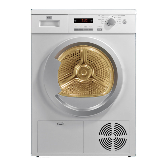
Tumble Dryer
HD80-01
HD70-01
Advertisement
Table of Contents

Related Manuals for Haier HD80-01


Summary of Contents for Haier HD80-01
-
Page 1: Document Control
Tumble Dryer HD80-01 Model No. HD70-01 WARNING This service information is designed for experienced repair technicians only and is not designed for use by the general public. It dode not contain warnings or cautions to advise non-technical individuals of potendtial dangers in attempting to service a product. -
Page 2: Table Of Contents
Issue Service Manual Rev. Model No: HD80-01/HD70-01 Table of Contents Document control ......................1 Chapter 1. General Information ................... 2 1-1. Table of Contents 1-2. General Guidelines 1-3. Caution and Warning symbols 1-4. Function indication symbols Chapter 2. Product Feature ..................4 2-1. -
Page 3: General Guidelines
Issue Ser vice Manual Rev. Model No: HD80-01/HD70-01 1-2. General Guidelines When servicing,observe the original lead dress.If a short circuit is found, replace all parts which are overheated or damaged by the short circuit.After servicing ,see to it that all the protective devices such as insulation barriers ,insulation papers shields are properly installed . -
Page 4: Chapter 2. Product Feature
Issue Service Manual Rev. Model No: HD80-01/HD70-01 Chapter 2. Product Feature 2-1. Features Features Condenser Tumber Dryer Energy class B LED Display Delay time adjustive - 4 -... -
Page 5: 2-2.Specification
Service Manual Issue Rev. Model No: HD80-01/HD70-01 2-2. Specification Front loaders dryer HD80- 01 HD70- 01 Product identification Description of appliance Dryer Dryer Type of appliance (FS = standing, BI = built- in) Supplier own brand Haier Haier Supplier bar code... - Page 6 Service Manual Issue Rev. Model No: HD80-01/HD70-01 Basics data Unit dimensions (H x W x D) 84. 5x 59. 5 x64 84.5x 59. 5 x64 Net weight Voltage/ frequency V/ Hz 220~240V/ 50Hz 220~240V/ 50Hz Input power(Max) 2700W 2700W Control M = electromechanical,...
-
Page 7: Chapter 3. Important Safety Instructions
Issue Ser vice Manual Rev. Model No: HD80-01/HD70-01 Chapter 3. Important Safety Instructions 3-1 Before switching the device on for the first time 1.Ensure that the device is installed and electrically grounded by a qualified service person in accordance to local codes to prevent shock hazard and assure tability during operation. -
Page 8: Chapter 4. Operation Instructions
Issue Ser vice Manual Rev. Model No: HD80-01/HD70-01 Chapter 4. Operation instructions 4-1 Control panel 4.1.1 Power button Press this button to turn the tumble dryer on and off. Power 4.1.2 Start/Pause button Press this button to start the tumble dryer. Press this button again during the operation of the tumble dryer.The indicator light and display screen will... - Page 9 Issue Ser vice Manual Rev. Model No: HD80-01/HD70-01 4.1.3 Programme Turn the knob to choose the desired drying program.There have 10 progrmme options. Time Very dry Synthetic 30min 20min Normal Cotton Damp Damp Normal Wool Very dry Cool MAX LOAD...
- Page 10 Issue Ser vice Manual Rev. Model No: HD80-01/HD70-01 4.1.4 Display sceen The display shows the remaining program time,the delay time and other related information. After each dyring cycle or the tank After each dyring cycle the icon is full,the icon will turns on,the tank will turns on,the filterneed be need be emptied.
-
Page 11: Using The Tumble Dryer
Issue Ser vice Manual Rev. Model No: HD80-01/HD70-01 4-2 Using the tumble dryer 4.2.1 Connect the tumble dryer to the power supply (220V to 240V~/50Hz). 4.2.2 Loading the tumble dyer 4.2.3 Switch on the power supply Power 4.2.4 Selecting program,selecting functional 4.2.5 Drying... -
Page 12: Chapter 5. Part Identification
Issue Ser vice Manual Rev. Model No: HD80-01/HD70-01 Chapter 5. Part Identification drawer hold the drawer,the tank can be pulled top cover control panel outwards front panel outer frame of sight window handle pull the handle , screen of sight window... - Page 13 Issue Service Manual Rev. Model No: HD80-01/HD70-01 box of container drum door lock wheel support the drum base part condenser pipe pump Reinforcement belt capacitor motor foot -13 -...
- Page 14 Issue Ser vice Manual Rev. Model No: HD80-01/HD70-01 rubber support fixing the heater wire heater cover of air channel cover of fan process fan lamp cover unscrew 2 screws from the cover, it can be opened,the light can be replaced.
-
Page 15: Chapter 6. Disassembly Guide
Issue Ser vice Manual Rev. Model No: HD80-01/HD70-01 Chapter 6. Disassembly Guide 6-1 Control panel push 1) Unscrew 2 screws on the back of the top plate. 2) Pull the top plate backward and upward as shown. Pull out the tank. -
Page 16: Heater And Bearing
Issue Ser vice Manual Rev. Model No: HD80-01/HD70-01 6-2 Heater and bearing 1) Unscrew 15 screws on the rear cover. 2) Take out the cover from the rear panel. 1) Disassemble the top cover; heater wire 2) Disconnect the wire of heter. -
Page 17: Motor And Fans
Issue Ser vice Manual Rev. Model No: HD80-01/HD70-01 Unscrew 4 screws on the holder for bearing. bearing The bearing can be disassembled. heater wire 6-3 Motor and fans 1) Disassemble the top cover; 2) Unscrew 2 screws on the right side panel. - Page 18 Issue Ser vice Manual Rev. Model No: HD80-01/HD70-01 1)Disconnect the wire of motor and capacitor; 2)Disassemble the spring. 1) Unscrew 2 screws on the support of the capacitor; 2) Unscrew 8 screws on the cover of cooling fan. Unscrew 6 screws on the cover of process fan.
- Page 19 Issue Ser vice Manual Rev. Model No: HD80-01/HD70-01 1) Fixing the shaft of motor; 2) Unscrew the nut,disassemble the fan. Unscrew 3 screws on the support of motor; The motor can be be disassembled. The cooling fan can be disassembled.
-
Page 20: Pump
Issue Service Manual Rev. Model No: HD80-01/HD70-01 6-4 Pump 1) Disassemble the top panel; 2) Disassemble the left side panel. pipe the cover of pump 1) Take out the cover of pump; 2) Pull out the pipes. Unscrew 1 screw on the support of pump. -
Page 21: Front Air Channel
Issue Ser vice Manual Rev. Model No: HD80-01/HD70-01 6-5 Front air channel 1) Disassemble the top panel; 2) Disassemble the control panel. Disassemble the two side panel. Unscrew 5 screws on the top of front panel. Unscrew 2 screws on the hinge, disassemble the door. - Page 22 Issue Ser vice Manual Rev. Model No: HD80-01/HD70-01 1) Unscrew 3 screws on the middle of front panel. 2) Disassemble the sealing bar of door. 3)Disconnect the wire of door lock. Open the service panel,take out the condenser. Disassemble the cooling grid.
- Page 23 Issue Ser vice Manual Rev. Model No: HD80-01/HD70-01 1) Unscrew 4 screws on the box of tank. 2) Pull out the pipe; The box of tank can be disassem- bled. pipe Unscrew 1 screw on the front air channel. Pull the front air channel ahead,it can be disassembled.
-
Page 24: Belt
Issue Service Manual Rev. Model No: HD80-01/HD70-01 6-6 Belt Disassemble the motor; Disassemble the front air channel. The belt can be disassembled. -24 -... -
Page 25: Chapter 7. Schematic Diagram
Issue Ser vice Manual Rev. Model No: HD80-01/HD70-01 Chapter 7. Schematic Diagram NTC1 D2 NTC1 NTC2 W1 1-5 1-4 1-3 1-2 X2-1 X2-2 Power board Display board X3-1 X3-3 X4-4 X4-3 X4-2 HT-NTC1 HT-NTC1 NTC2 Thermalcut-out R1: Heating1 K1: Door switch... -
Page 26: Chapter 8. Circuit Interface Diagram
Issue Ser vice Manual Rev. Model No: HD80-01/HD70-01 Chapter 8. Circuit Interface Diagram Humidity sensor Power Heating1(850W) Heating2(1850W) Lamp Motor Pump NTC(near heater) NTC(near Filter) Water level switch Door switch -26 -... -
Page 27: Chapter 9. Fault Detection
Issue Ser vice Manual Rev. Model No: HD80-01/HD70-01 Chapter 9. Fault Detection The dryer does not start Insert the power plug into an The power supply plug peels off; appropriate receptacle to turn onthepower Put on the local circuit The local circuitis out of power;... -
Page 28: The Drying Result Is Not Good And The Drying Time Is Too Long
Issue Service Manual Rev. Model No: HD80-01/HD70-01 The drying result is not good and the drying time is too long. The drying program setting is not Set the drying program correct; correctly The filter screen has not been Clean the filter screen... -
Page 29: Code:f2
Issue Ser vice Manual Rev. Model No: HD80-01/HD70-01 Code:F2 Error message:The drain pump is failed. Empty the tank and Check if the tank is full with restart the dryer. water Check if there are some lints Clear the lints; aroud the floater ;... -
Page 30: Code:f4
Issue Ser vice Manual Rev. Model No: HD80-01/HD70-01 Code:F4 Erro rmessage:Temperature of the NTC(near the filter) does not change. Check if the filter is full with Clean the filter. lints Check if non-self-resetting Manual operation for thermal cut-out is cut;... -
Page 31: Chapter 10. Test Programme
Issue Ser vice Manual Rev. Model No: HD80-01/HD70-01 Chapter 10. Test Programme Order Operation Display and action pressing the two buttons(Delay The screen display "TEST" the test programme wil start,the LED lamp and Delicate),turn the power on; will light in turn The third LED screen will dislay the state of water level switch:open is 0,close is 1;... -
Page 32: Chapter 11. Electric Appliances Parameter
Service Manual Issue Rev. Model No: HD80-01/HD70-01 Chapter 11. Electric Appliances Parameter Order Part name Supplier Parameter Remark Model Blue Yellow Zhongshan Yellow Motor Y6S25 Broad-Ocean 0024000289 8C21 2600rpm Blue 220-240V/50Hz Motor Capacitor CBB65 AC 450V Various 00330506020 50/60Hz T85... - Page 33 Haier Group Haier Industrial Park, No.1, Haier Road 266101, Qingdao, China http://www.haier.com Printed in China...