Table of Contents
Advertisement
Quick Links
M The author assumes no responsibility for any errors
or omissions that may appear in this document nor
does the author make a commitment to up
date the information contained herein.
M Third-party brands and names are the property of
their respective owners.
M Please do not remove any labels on motherboard, this
may void the warranty of this motherboard.
M Due to rapid change in technology, some of the
specifications might be out of date before publication
of this booklet.
Advertisement
Table of Contents

Related Manuals for Gigabyte GA-8IPXDR


Summary of Contents for Gigabyte GA-8IPXDR
- Page 1 M The author assumes no responsibility for any errors or omissions that may appear in this document nor does the author make a commitment to up date the information contained herein. M Third-party brands and names are the property of their respective owners.
- Page 2 (818) 854-9338/ (818) 854-9339 hereby declares that the product Product Name: Motherboard Model Number: GA-8IPXDR Conforms to the following specifications: FCC Part 15, Subpart B, Section 15.107(a) and Sect ion 15.109(a), Class B Digital Device Suppl ementary Information: This device co mplies with part 15 of the FCC Rules . Operation is...
-
Page 3: Declaration Of Conformity
Ausschlager Weg 41, 1F, 20537 Hamburg, Germany declare that the product ( description of the apparatus, system, installation to which i t refers) Mother Board GA-8IPXDR is in conformity with (reference to the specification under which conformity is declared) in accordance with 89/336 EEC-EMC Directive... - Page 4 GA-8IPXDR Processor Motherboard USER’ S MANUAL Pentium Xeon Processor Motherboard ® Rev. 1102 12ME-8IPXDR-1102...
-
Page 5: Table Of Contents
Item Checklist ..................4 WARNING! ..................5 Chapter 1 Introduction ...............6 Features Summary....................6 GA-8IPXDR Motherboard Layout ............... 8 Chapter 2 Hardware Installation Process ..........9 Step 1: Install the Central Processing Unit (CPU) ......... 10 Step 1-1: ....................10 Step 1-2: CPU Installation ................11 Step 1-3: CPU Heat Sink Installation .............. - Page 6 Table of Content Chapter 4 Technical Reference ............51 Block Diagram ..................... 51 Chapter 5 Appendix ................ 52...
-
Page 7: Revision History
GA-8IPXDR Motherboard Revision History Revision Revision Note Date Initial release of the GA-8IPXDR motherboard user's manual. Feb. 2002 Item Checklist þ The GA-8IPXDR motherboard þ I/O Back Panel þ IDE cable x 1/ Floppy cable x 1 USB Cable x 1(Optional) þ... -
Page 8: Warning
WARNING! WARNING! Computer motherboards and expansion cards contain very delicate Integrated Circuit (IC) chips. To protect them against damage from static electricity, you should follow some precautions whenever you work on your computer. Unplug your computer when working on the inside. Use a grounded wrist strap before handling computer components. -
Page 9: Chapter 1 Introduction
GA-8IPXDR Motherboard Chapter 1 Introduction Features Summary Form Factor — 30.5cm x 33cm Extend ATX size form factor, 8 layers PCB. — Socket 603 for Intel FC-PGA Prestonia processor ® — Intel Prestonia 400MHz FSB — 512KB cache depend on CPU Chipset —... - Page 10 Introduction On-Board LAN — Build in Intel Dual RC82544GC series 10/100/1000 Ethernet Chipset (Server Adaptec) On-Board VGA — Build in ATI Rage XL VGA PCI Chipset On-Board SCSI — Adaptec 7899W SCSI Chipset (Optional 7902) PS/2 Connector — PS/2 Keyboard interface and PS/2 Mouse interace BIOS —...
-
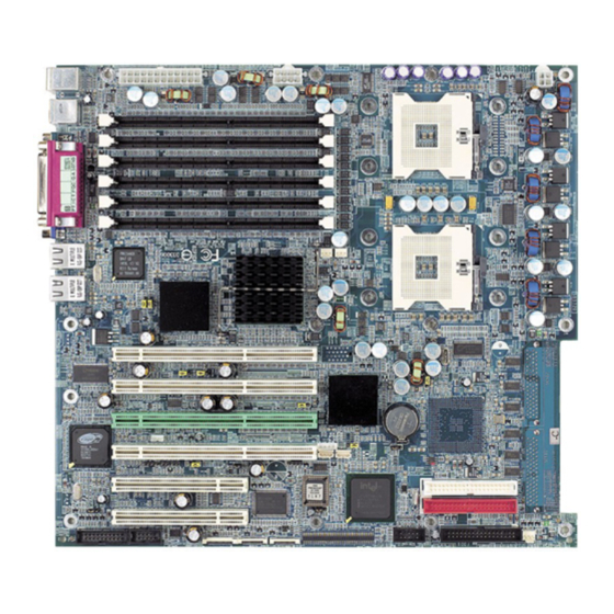
Page 11: Ga-8Ipxdr Motherboard Layout
GA-8IPXDR Motherboard GA-8IPXDR Motherboard Layout ATX3 ATX1 ATX2 USB2 603 PIN Socket GA-8IPXDR RC82544GC RG82861 RG82870P2 RC82544GC 603 PIN Socket PCI1 PCI2 RG82870P2 PCI3 SCSI AIC-7899W ATI R age CASEOPEN IDE2 PCI4 BIOS FW 82801CA COM2 IDE1 PCI5 IPMI_CON1 IPMI_CON2... -
Page 12: Chapter 2 Hardware Installation Process
Hardw are Installation Process Chapter 2 Hardware Installation Process To set up your computer, you must complete the following setups: Step 1- Install the Central Processing Unit (CPU) Step 2- Install memory modules Step 3- Install expansion cards Step 4- Connect ribbon cables, cabinet wires, and power supply Step 5- Setup BIOS software Step 6- Install supporting software tools Step 2... -
Page 13: Step 1: Install The Central Processing Unit (Cpu)
GA-8IPXDR Motherboard Step 1: Install the Central Processing Unit (CPU) Step 1-1: You may use the 4 screws which come with the mai n board to reinforce the support between Xeon CPU heat-sink on the mainboard and chassis. Step2: Step1: The 4 new mounting holes on t h e chassis are for additional support for Xeon CPU heat-sink on the mainboard. -
Page 14: Step 1-2: Cpu Installation
Hardw are Installation Process Step 1-2: CPU Installation Pin1 indicator CPU Top View CPU Bottom View Pin1 indicator Socket Actuation Lever 1. Pull the lever out, than lift up the Lever. 2. Locate Pin 1 in the socket and look for a (golden) cut edge on the CPU upper corner. -
Page 15: Step 1-3: Cpu Heat Sink Installation
GA-8IPXDR Motherboard Step 1-3: CPU Heat Sink Installation 1. Use qualified fan approved by Intel. 2. Heat Sink 3. First step of assembling. 4. Completive picture for first step. 5. Second step of assembling. 6. Completive picture for second step. - Page 16 Hardw are Installation Process 7. Fan assembly. 8. Hook one end of the cooler bracket to the CPU socket first. 9. Picture of device set on the motherboard. M Please use Intel approved cooling fan. M We recommend you to apply the thermal paste to provide better heat conduction between your CPU and heatsink.
-
Page 17: Step 2: Install Memory Modules
GA-8IPXDR Motherboard Step 2: Install memory modules The motherboard has 6 dual inline memory module (DIMM) sockets. The BIOS will automatically detects memory type and size. To install the memory module, just push it vertically into the DIMM Slot. The DIMM module can only fit in one direction due to the notch. Memory size can vary between sockets. -
Page 18: Step 3: Install Expansion Cards
Hardw are Installation Process Step 3: Install expansion cards 1. Read the related expansion card’ s instruction document before install the expansion card into the computer. 2. Remove your computer’ s chassis cover, screws and slot bracket from the computer. 3. -
Page 19: Step 4: Connect Ribbon Cables, Cabinet Wires, And Power Supply
GA-8IPXDR Motherboard Step 4: Connect ribbon cables, cabinet wires, and power supply Step 4-1: I/O Back Panel Introduction u PS/2 Keyboard and PS/2 Mouse Connector PS/2 Mouse Connector ØThis connector supports standard PS/2 (6 pin Female) keyboard and PS/2 mouse. - Page 20 Hardw are Installation Process w Parallel Port / Serial Port / VGA Port (LPT/COMA/VGA) Parallel Port (25 pin Female) ØThis connector supports 1 standard COM port ,1 Parallel port and 1 VGA port. Device like printercan be connected to Parallel port ; mouse and modem etc can be connected to Serial ports.
-
Page 21: Step 4-2: Connectors Introduction
GA-8IPXDR Motherboard Step 4-2: Connectors Introduction A) ATX3 J) IPMI_CON1/IPMI_CON2 B) ATX1 K) F_PANEL1 C) ATX2 L) COM2 D) BT1 M) J20 E) SCSI1/SCSI2 N) CASEOPEN F) J34 O) J31 G) FDD1 P) J18 H) USB1 Q) J33 I ) IDE1/IDE2... - Page 22 Hardw are Installation Process A) ATX3 (2x12 Pin ATX Power ) PSON - 12V +3.3V +3.3V +3.3V +12V 5VSB Ø AC power cord should onl y be connected t o your power supply unit after ATX power cable and other related devices are firmly connected to the mainboard.
- Page 23 GA-8IPXDR Motherboard R) J30/J32 (CPU FAN Connector) ØPlease note, a proper installation of the CPU cooler is essential to prevent the CPU from Sense running under abnormal condition or damaged by overheating.The CPU fan connector +12V/Control supports Max. current up to 600mA .
- Page 24 Hardw are Installation Process E) SCSI1/SCSI2 Connector I) IDE1/IDE2 [IDE1 / IDE2 Connector(Primary/Secondary)] IDE2 ØImportant Notice: Please connect first harddisk to IDE1 and connect CDROM to IDE2. IDE1 N) CASE OPEN G) FDD1 (Floppy Connector) Floppy Signal M) J20 (For 2U Display Connector)
- Page 25 GA-8IPXDR Motherboard H) USB1 (Front USB Connector) USB D3+ ØBe careful with the polarity of the front panel USB connector. Check the pin assignment USB D3- Power while you connect the front panel USB cable. Please contact your nearest dealer for optional front panel USB cable.
- Page 26 Hardw are Installation Process K) F_PANEL1 (2x11 pins connector) P-P-P+ GN (Green Switch) Open: Normal Operation Close: Entering Green Mode GD (Green LED) Pin 1: LED anode(+) Pin 2: LED cathode(-) HD (IDE Hard Disk Active LED) Pin 1: LED anode(+) Pin 2: LED cathode(-) SPK (Speaker Connector) Pin 1: VCC(+)
-
Page 27: Step 4-3: Jumper Setting Introduction
GA-8IPXDR Motherboard Step 4-3: Jumper Setting Introduction 1) JP1 4) JP8 2) JP9 5) JP10 3) CLR_CMOS... - Page 28 Hardw are Installation Process 1) JP1 (Onboard SCSI Function) 1-2 close: SCSI Enabled (Default) 2-3 close: SCSI Disabled 2) JP9 (USB Device Wake up Functon) 1-2 close: Disabled 2-3 close: Enabled (Default) 3) CLR_CMOS (Clear CMOS Function) Ø Please note, You may clear the CMOS data to 1-2 close: Clear CMOS its default values by this jumper 2-3 close: Normal (Default)
-
Page 29: Chapter 3 Bios Setup
GA-8IPXDR Motherboard Chapter 3 BIOS Setup BIOS Setup is an overview of the BIOS Setup Program. The program that allows users to modify the basic system configuration. This type of information is stored in battery-backed CMOS RAM so that it retains the Setup information when the power is turned off. -
Page 30: Getting Help
BIOS Setup GETTING HELP Main Menu The on-line description of the highlighted setup function is displayed at the bottom of the screen. Status Page Setup Menu / Option Page Setup Menu Press F1 to pop up a small help window that describes the appropriate keys to use and the possible selections for the highlighted item. -
Page 31: Main (For Example: Bios Ver. : F8)
GA-8IPXDR Motherboard Main (For example: BIOS Ver. : F8) Once you enter AMI BIOS CMOS Setup Utility, the Main Menu (Figure 1) will appear on the screen. Use arrow keys to select among the items and press <Enter> to accept or enter the sub-menu. -
Page 32: Processor Speed
BIOS Setup C Process or Type This field only displays the type of present CPU. C Processor Speed This field indicates the speed of present CPU. C System Memory This field displays the installed memory size. C System TIme The time i s calculated nased on the 24-hour mil i tary time clock. Set the System Time (HH:MM:SS) C System Date Set the System Date. -
Page 33: Advanced
GA-8IPXDR Motherboard Advanced CMOS BISO Setup Utility Main Adv anced PCIPnP Chipset ACPI Boot Security Ex it Setup Warning Setting Up items on this screen to incorrect v alues may cause the sy stem to malfunction! } IDE Configuration } Floppy Configuration... -
Page 34: Floppy Configuration
BIOS Setup Advanced CMOS BISO Setup Utility Main Adv anced PCIPnP Chipset ACPI Boot Security Ex it Onboard PCI IDE Controller [Both] } Primary IDE Mater [Hard Disk] } Primary IDE Slav e [Not Detect] } Secondary IDE Master [ATAPI CDROM] } Secondary IDE Slav e [Not Detect] Select Screen... - Page 35 GA-8IPXDR Motherboard and security, etc. C IDE Confi guration This category allow user to configure the IDE device(s) . } Onboard PCI IDE Controller BOTH: Enables both IDE Controller DISABLED: Disables the integrated IDE Controller PRIMARY: Enables only the PrimaryIDE Controller...
-
Page 36: C Floppy Configuration
BIOS Setup 8 PIO Mode: This option allows user to select the PIO Mode. The Choices: Auto (Defaults), 0,1,2,3,4, 8 DMA Mode: This option allows user to select the DMA Mode. Auto(Default): Auto detect SWDMAn: Single Word DMAn MWDAMn: Multi Word DMAn UDMAn: Ultra DMAn 8 S.M.A.R.T: S.M.A.R.T. -
Page 37: Quick Boot
GA-8IPXDR Motherboard C Boot Setting Config uration } Quick Boot This setting all o ws BIOS to skip certain tests while booting. This will decrease the time needed to boot the system. The Choice: Disabled, Enabled (Default) } Quiet Boot Disabled: Displays normal POST message. - Page 38 BIOS Setup } System Keyboard This option does not specif y if a keyboard is att a ched to the computer. Rather, it specifies if error message are displayed if a keyboard is not attached. This option permits you to configure workstation or server with no keyboards.
-
Page 39: Super Io Configuration
GA-8IPXDR Motherboard C Super IO Configuration When user enters the screen of Super IO Configuration, a message “ Confiure Nat 366 Serial Port(s) and Parallel Port” appears at the up left corner of the screen. The message varies, depending on the BIOS version. -
Page 40: Usb Function
BIOS Setup ! EPP: The parallel port can be used wi t h devices that adhere to the Enhanced Parallel Port ( EPP ) specifications. EPP uses the existing parallel port signal to provide asymmetric bi-directional data transfer driven by the host device. ! ECP: The parallel port can be used with devices that adhere to the Extended Capabilities Port specifications. - Page 41 GA-8IPXDR Motherboard Enabled: Enables USB host Controller Disabled: Disables USB host Controller The Choice: Enabled, (Default), Disabled } Legancy USB Support This option allows user to function support for legacy USB. Auto: System auto detects the format of legacy USB...
-
Page 42: Pcipnp
BIOS Setup PCIPnP CMOS BIOS Setup Utility Main Adv anced PCIPnP Chipset ACPI Boot Security Ex it Plug & Play OS [Enabled] Reset Config Data Select Screen Select item Change Field Select Field General Help Sav e and Ex it Ex it V 02.10 (C) Copy right 1985-2001, American Megatrends, Inc Figure 3: PCIPnP... - Page 43 GA-8IPXDR Motherboard C Plug & Play O/S NO: Dose notforce the PnP data to be cleared on boot. YES: Clears PCI / PnP Configuration Data stored in Flash on next boot. The C hoice: No (Default) , Yes...
-
Page 44: Chipset
BIOS Setup Chipset CMOS BIOS Setup Utility Main Adv anced PCIPnP Chipset ACPI Boot Security Ex it }Chipset Configuration [Enabled] Select Screen Select item Change Field Select Field General Help Sav e and Ex it Ex it V 02.10 (C) Copy right 1985-2001, American Megatrends, Inc Figure: 4 Chipset About This Section: Chipset This secti o n allows you to configure the system based on the specific features of the built-in chipset. -
Page 45: Acpi
GA-8IPXDR Motherboard ACPI CMOS BIOS Setup Utility Main Adv anced PCIPnP Chipset ACPI Boot Security Ex it }ACPI Aare O / S Select Screen Select item Change Field Select Field General Help Sav e and Ex it Ex it V 02.10 (C) Copy right 1985-2001, American Megatrends, Inc... -
Page 46: Boot
BIOS Setup Boot CMOS BIOS Setup Utility Main Adv anced PCIPnP Chipset ACPI Boot Security Ex it } Boot Dev ice Prioritu } Hard Disk Driv e } Remov able Dev ices Select Screen } ATAPI CDROM Select item Change Field Select Field General Help Sav e and Ex it... - Page 47 GA-8IPXDR Motherboard The Choice for 1st Boot Device: Removable Device (Default) , ATAPI CDROM, Hard Disk, Disabled. The Choice for 2nd Boot Device: Removable Device , ATAPI CDROM (Default) , Hard Disk, Disabled. The Choice for 3rd Boot Device: Removable Device , ATAPI CDROM, Hard Disk (Default), Disabled.
-
Page 48: Security
BIOS Setup Security CMOS BIOS Setup Utility Main Adv anced PCIPnP Chipset ACPI Boot Security Ex it Superv isor Passw ord: Installed User Passw ord: Installed Change Superv isor Passw ord User Access Lev el [Full Access] fg Select Screen Change User Passw ord Select item Clear User Passw ord... - Page 49 GA-8IPXDR Motherboard CChange Supervisor Password You can install and change the options for the setup menus. Type the password up to 6 characters in lengh and press <Enter>. The password typed now will clear any prev iously entered password from the CMOS memory. You w ill be asked to confirm the entered password.
- Page 50 BIOS Setup CPassword Check Setup will check passw ord while invlolking setup. Alw ays will check the password w hile involking setup as well as on each boot. The Choice: Setup (Default), A lways CBoot Sector Virus Protection This option alllows user to enable / disable the function of virus protection. Any action attempt to modify the data of boot sector during POST will be forbidden if this function is enabled.
-
Page 51: Exit
GA-8IPXDR Motherboard Exit CMOS BIOS Setup Utility Main Adv anced Boot Serv er Security Defaults Ex it Ex it Sav ing Changes Ex it Discarding Changes Load Optimal Defaults Load Failsafe Defaults fg Select Screen Discard Changes Select item Change Field... - Page 52 BIOS Setup CExit Saving Changes This option allows user to exit system setup with saving the changes. Press <Enter> on this item to ask for the following confirmation message: Pressing ‘ Y’ to store all the present setting values tha user made in this time into CMOS. Therefore, whenyou boot up y our computer next time, the BIOS will re-configure your system according data in CMOS.
- Page 53 GA-8IPXDR Motherboard CDiscard Changes This allows user not changing any previous setting values in CMOS . The prev ious selections remain in effect. Press <Enter> on this item to ask confirmation. ! Note: For fast setting up a system at the first time, we strongly recommend to load system...
-
Page 54: Chapter 4 Technical Reference
Technical Reference Revision History Chapter 4 Technical Reference Block Diagram... -
Page 55: Chapter 5 Appendix
GA-8IPXDR Motherboard Revision History Chapter 5 Appendix (For example: Driver CD Ver. : 1.1) Appendix A: Inf Update Utility Installation Insert the driver CD-title that came with your motherboard into your CD-ROM driver, the driver CD-title will auto start and show the installation guide. If not, please double click the CD-ROM device icon in "My computer", and execute the setup.exe. - Page 56 Appendix 5.Click "Finish" to restart computer.
- Page 57 GA-8IPXDR Motherboard Appendix C: Intel 82544GC LAN Utility Insert the driver CD-title that came with your motherboard into your CD-ROM driver, the driver CD-title will auto start and show the installation guide. If not, please double click the CD-ROM device icon in "My computer", and execute the setup.exe.
- Page 58 Appendix 6.Click "Imstall". 5.Click "Install". 7.Click "Finish". 8.Click "OK"...
- Page 59 GA-8IPXDR Motherboard Appendix D: ATI -Range XL VGA Driver Insert the driver CD-title that came with your motherboard into your CD-ROM driver, the driver CD-title will auto start and show the installation guide. If not, please double click the CD-ROM device icon in "My computer", and execute the setup.exe.
- Page 60 Appendix Appendix G: Acronyms Acronyms Meaning ACPI Advanced Configuration and Power Interface Advanced Power Management Accelerated Graphics Port Audio Modem Riser Advanced Communications Riser BIOS Boot Specification BIOS Basic Input / Output System Central Processing Unit CMOS Complementary Metal Oxide Semiconductor CRIMM Continuity RIMM Communication and Networking Riser...
- Page 61 GA-8IPXDR Motherboard Acronyms Meaning Local Area Network Logical Block Addressing Light Emitting Diode Megahertz MIDI Musical Instrument Digital Interface Memory Translator Hub Memory Protocol Translator Network Interface Card Operating System Original Equipment Manufacturer PCI A.G.P. Controller POST Power-On Self Test...
- Page 62 Appendix Technical Support/RMA Sheet Customer/Country: Company: Phone No.: Contact Person: E-mail Add. : Model name/Lot Number: PCB revision: BIOS version: O.S./A.S.: Hardware Mfs. Model name Size: Driver/Utility: Configuration Memory Brand Video Card Audio Card CD-ROM / DVD-ROM Modem Network AMR / CNR Keyboard Mouse Power supply...