
Related Manuals for Oreck Super Air 5 447628


Summary of Contents for Oreck Super Air 5 447628
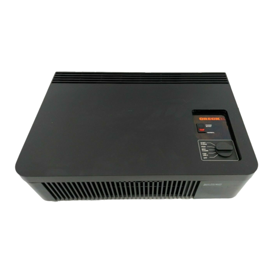
- Page 1 ® S I M P L Y A M A Z I N G Service Manual Table Top Air Cleaner Super Air 5 / Air 6 Model 447628 & 4478801 REV I., Please disregard all earlier versions.
- Page 2 General Knowledge Warning - The intent of this manual is to provide general guidance to be used by a qualified service technician in servicing the Oreck tabletop electrostatic air cleaner. The technician should have a good understanding relative to working with electrical and mechanical equipment.
-
Page 3: Table Of Contents
- smoke and bacteria, to name a few, are microscopic in size. Polluted air enters the unit through the front of the air cleaner. The fan pulls in dirty air and the pre-filter traps large particles (hair, lint, etc.). The smaller particles (dust, smoke, pollen) in the dirty air receive a positive electrical charge as they pass through the ionizing section. -
Page 4: Periodic Maintenance And Tune-Up
1. Remove collecting cell and pre/post filters. 2. Wipe down inside of unit with damp cloth. 3. Thoroughly Clean Collecting Cell with Oreck Assail-A-Cell Cleaner. 4. Check for any broken wires in the collecting cell, and ensure wires are securely seated in the plastic spacer at the center of the cell. -
Page 5: Troubleshooting Guide
Warning: The troubleshooting portion of this manual requires that the unit power be “ON” for much of the servicing portion of troubleshooting. When working on the unit under power, use all of the standard precautions in working with any electro-mechanical device that contains line voltage, high voltage, and rotating elements. - Page 6 How to Remove the Power Supply Cover Insert flathead screwdriver into slot on the interior edge of the power supply cover, and push plastic clip away from contact wall so that the cover can be lifted up. The switch wires will limit the movement of the power supply cover. Is the switch actuator broken? Is the switch properly seated in the bracket, or is the bracket broken or distorted? The switch is held in position by a bracket that allows the switch to be snapped...
- Page 7 Check the voltage to and from the switch when activated. You should be able to measure line voltage entering and leaving the switch when activated. Check the switch plate cover. The plate must sit squarely on the bearing wall and the cabinet base. 2.
- Page 8 c. If the light does not operate with the cell removed, check the wires to the light and confirm that they are properly connected. Check the voltage from the light terminals on the power supply board. Set meter to appropriate scale. You should have about 16 volts DC.
- Page 9 e. Check the input voltage to the transformer using a standard lead and a multimeter. Check the voltage from the black lead on the terminal L speed control switch and white lead on power supply board labeled line neutral. Activate the interlock switch. The meter should indicate line voltage.
- Page 10 d. If there are no signs of distortion, remove the blower wheel (see: Blower Wheel Removal) and activate the unit. Notice if the motor shaft rotates without the blower wheel. If the motor shaft operates, the problem is related to the blower wheel. 4.
- Page 11 c. Check to see if the blower wheel is adequately supported by the outside bearing plate assembly. d. Check to see if the motor mounting bracket snap tabs are in place or are loose. Look into the four base slots to see the tabs. e.
- Page 12 If the cell is arcing, check the following: a. If there are loose or broken ionizer wires. b. If the cell is dirty. Remove the cell and wash with warm soapy water. Dry completely before re-installing. c. If there are bent cell plates. d.
- Page 13 If the H.V. contacts are not properly aligned or the contact wall is not properly aligned. 7. Checking for ionizing needle operation. Using HV voltage probe check needle for high voltage -5.5 KVDC to -7.0 KVDC. a. If voltage is present, the ionizer is OK. b.
- Page 14 Notes _____________________________________________________________________________ _____________________________________________________________________________ _____________________________________________________________________________ _____________________________________________________________________________ _____________________________________________________________________________ _____________________________________________________________________________ _____________________________________________________________________________ _____________________________________________________________________________ _____________________________________________________________________________ _____________________________________________________________________________ _____________________________________________________________________________ _____________________________________________________________________________ _____________________________________________________________________________ _____________________________________________________________________________ _____________________________________________________________________________ _____________________________________________________________________________ _____________________________________________________________________________ _____________________________________________________________________________ _____________________________________________________________________________ _____________________________________________________________________________ _____________________________________________________________________________ _____________________________________________________________________________ _____________________________________________________________________________ _____________________________________________________________________________ _____________________________________________________________________________ _____________________________________________________________________________ _____________________________________________________________________________ _____________________________________________________________________________...
-
Page 15: Parts Removal And Replacement Procedures
Parts Removal and Replacement General Parts Replacement Motor Removal and Replacement Power Supply Removal and Replacement Transformer Removal and Replacement Bearing Wall Assembly and Blower Wheel Removal and Replacement Led Assembly Removal and Replacement Cell Assembly Removal and Replacement Ionizer Needle Removal and Replacement Fan Blade Removal and Replacement Warning - All parts removal and replacement should be performed with power disconnected from the unit. -
Page 16: General Parts Replacement
Motor Removal and Replacement 1. Remove the cabinet top by pressing down the thumb latch and sliding the top forward. 2. Remove the cell assembly (see inside of top for instructions). 3. Remove the stripper by pulling it to the right and applying pressure to the bearing wall. - Page 17 ROTATING ELEMENT WARNING - Unit has a rotating blower wheel and cooling fan to circulate air and keep the unit cool. When servicing the unit and repairing the unit always insure that you keep objects and internal electrical wiring away from the rotating elements.
- Page 18 HIGH VOLTAGE WARNING - This equipment is supplied with line voltage from a standard wall socket. Use standard precautions in working on it with line voltage applied. Failure to practice normal electrical safety precautions can cause electrical shock, personal injury or property damage. 9.
-
Page 19: Power Supply Removal And Replacement
Power Supply Removal and Replacement 1. Follow steps 1, 3, and 6 of Motor Removal and Replacement. EXTREME HIGH VOLTAGE WARNING - This equipment is supplied with line voltage from a standard electrical wall socket. That voltage is transformed to a 24V signal that is then amplified to over 6000VDC. - Page 20 All leads must be connected to the new board properly. The HV power line must be isolated and properly routed. Two insulator sheets must be in position and all wiring must be captured to prevent contact with rotating elements. A wiring diagram is included in the service manual for your use.
-
Page 21: Transformer Removal And Replacement
5. To test the power supply, touch the metal shaft of a screwdriver, with an insulated or plastic handle, to one of the contacts while keeping the screwdriver tip about 1/8" away from the other contact. You should see an arc and hear a snapping sound. 6. -
Page 22: Bearing Wall Assembly And Blower Wheel Removal And Replacement
3. Remove the two #8/32 lockwasher nuts and remove the transformer and replace it with the new unit. 4. Reverse the above steps 1,2, and 3 to replace the transformer. Bearing Wall Assembly and Blower Wheel Removal and Replacement 1. Follow steps 1, 2, 3, 4 and 5 of Motor Removal and Replacement. 2. -
Page 23: Led Assembly Removal And Replacement
Led Assembly Removal and Replacement 1. Follow steps 1, 2, and 6 of Motor Removal and Replacement. 2. Disconnect the two red led leads from the power supply board and remove the led assembly by removing the led retaining ring from the back of the front panel and removing the led and the leads. -
Page 24: Fan Blade Removal And Replacement
EXTREME HIGH VOLTAGE WIRING WARNING - The unit has been designed such that extremely high cell collector voltage wiring is isolated from all other wiring. Special wiring routing holders have been designed into the unit. This extremely high voltage wiring must be routed correctly. Failure to route and isolate the wire can create a fire hazard, personal injury or property damage. -
Page 25: Cross Section And Parts List
ITEM # PART NO. 242235-001 242331-007 242404-001 247135-001 AT2PK 247667-001 342472-002 342480-003 254682-001 254681-001 451686-003 442415-101 142475-001 342228-001 342227-001 136483-001 342402-251 342402-254 442223-201 242253-001 142581-001 145820-002 40184-01 442414-001 20CFT 30CFT 33358 242809-015 DESCRIPTION SWITCH KNOB, BLACK TRANSFORMER INTERLOCK SWITCH FAN BLADE CHARCOAL COMBINATION FILTER CONTROL LABEL CONTACT WALL ASSEMBLY... -
Page 26: Wiring Diagram
POWER POS 3 L-1,4 SWITCH OUTPUT POS 4 L-2,4 POS 5 L-3,4 ©2004 Oreck Holdings, LLC. All rights reserved. All trademarks are owned and used under the authority of Oreck Holdings, LLC. BLACK (RIBBED) BLOWER 120V RED (142475-001) BLUE (242477-035) - Page 27 Notes _____________________________________________________________________________ _____________________________________________________________________________ _____________________________________________________________________________ _____________________________________________________________________________ _____________________________________________________________________________ _____________________________________________________________________________ _____________________________________________________________________________ _____________________________________________________________________________ _____________________________________________________________________________ _____________________________________________________________________________ _____________________________________________________________________________ _____________________________________________________________________________ _____________________________________________________________________________ _____________________________________________________________________________ _____________________________________________________________________________ _____________________________________________________________________________ _____________________________________________________________________________ _____________________________________________________________________________ _____________________________________________________________________________ _____________________________________________________________________________ _____________________________________________________________________________ _____________________________________________________________________________ _____________________________________________________________________________ _____________________________________________________________________________ _____________________________________________________________________________ _____________________________________________________________________________ _____________________________________________________________________________ _____________________________________________________________________________...
- Page 28 ©2004 Oreck Holdings, LLC. All rights reserved. All trademarks are owned and used under the authority of Oreck Holdings, LLC. 75422-01 REV I 08/04 R-7693, R-7695...