Electrolux W465H Service Manual
Washer extractors
Hide thumbs
Also See for W465H:
- Service manual (122 pages) ,
- Operating manual (76 pages) ,
- Installation manual (60 pages)
Table of Contents
Advertisement
Quick Links
Advertisement
Table of Contents

Related Manuals for Electrolux W465H


Summary of Contents for Electrolux W465H
- Page 1 Service manual Washer extractors W465H–W4300H, W475S–W4330S, W475N–W4330N Type W3... Compass Control From machine No. W475N/S, W485N/S, W4105N/S, W4130N/S 00521/402183- W4180N/S 00650/107384- W4250N/S 00725/105494- W4330N/S 00795/102510- 438 9228-61/EN Service manual in original language 2011.08.25...
-
Page 3: Table Of Contents
Contents Contents Safety precautions ..................5 Technical data ....................7 Machine presentation ................13 Description .................... 13 Function ....................14 Program unit ..................16 Motor and motor control ............... 17 Door lock ....................18 Heating ....................19 Water connections ................19 Rear electric module ................ - Page 4 Contents Drain valve ....................89 Description .................... 89 Function ....................90 Repairs ....................91 Detergent compartment ................93 Description .................... 93 Heating ....................... 95 Description .................... 95 Function ....................96 Repairs ....................98 Payment systems ..................99 Abbreviations ................... 101 Preventive maintenance ................
-
Page 5: Safety Precautions
Safety Precautions Safety Precautions The machine is only intended for water-wash use. Do not allow minors to use the machine. Do not hose down the machine with water. The machine's door lock must under no circumstances be bypassed. If the machine develops a fault, this must be reported to the person in charge as soon as possible. -
Page 7: Technical Data
Technical data Technical data W465H W475H W4105H W4130H W4180H W4240H W4300H Innerdrum volume litres diameter Drum speed wash extraction 1100 1100 1025 Heating 5.4/5.6/7.5 5.4/5.6/7.5 5.6/7.5/10 electricity steam hot water G-factor Weight, net Connections W465H W475H W4105H W4130H W4180H W4240H... - Page 8 Technical data Technical data W475N/S W485N/S W4105N/S W4130N/S W4180N/S W4250N/S W4330N/S Innerdrum volume litres diameter Drum speed wash extraction 587/830 587/830 548/776 548/776 525/742 497/702 474/671 2.0/3.0/ 2.0/3.0/ 3.0/5.6/ 3.0/ 4.8/9.3 Heating electricity 5.4/5.6/7.5 5.4/5.6/7.5 6.5/7.5/10 7.5/10 steam hot water G-factor 100/200 100/200...
- Page 9 Hard water Steam connection Drain Liquid detergent supply Control panel Soap box Door opening, W465H, W475H: ø 310, W4105H: ø 365, W4130H: ø 395, W4180H, W4240H, W4300H: ø 435 W465H 720 690 1115 355 1030 220 1010 135 100 240 –...
- Page 10 Technical data Electrical connection Cold water Hot water Steam connection Drain Liquid detergent supply Control panel Soap box Water reuse Door opening, W475N/S, W485N/S: ø310, W4105N/S, W4130N/S: ø365, W4180N/S: ø395, W4250N/S, W4330N/S: ø435 W475N/S 690 1115 355 45 1030 215 1010 130 W485N/S 730 1115 355 45 1030 215 1010 130...
- Page 11 Technical data W465H W475H W4105H W4130H W4180H W4240H W4300H Frequency of the dynamic force 18.3 18.3 17.1 16.3 15.5 14.8 13.7 Floor load at max extraction 1.8 ± 0.5 1.9 ± 0.5 2.5 ± 0.5 3.1 ± 0.5 4.2 ± 1.0 5.2 ±...
-
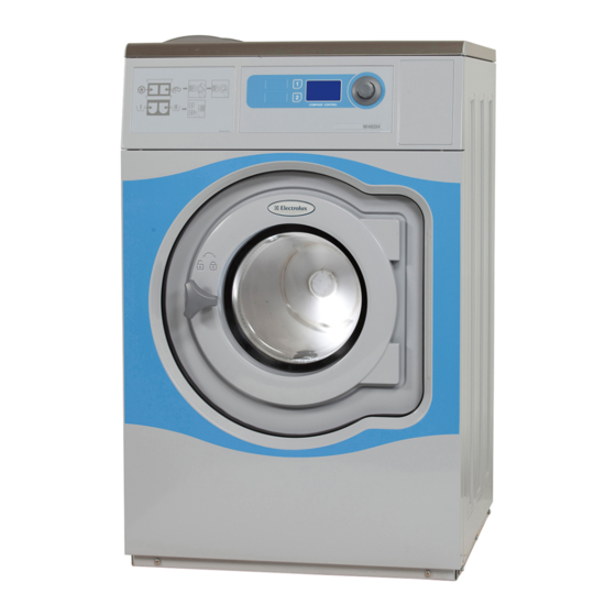
Page 13: Machine Presentation
Machine presentation Machine presentation Description The machines covered in this service manual include the following models: Drum volume Model name (litres) W465H W475H/S/N W485S/N W4105H/S/N W4130H/S/N W4180H/S/N W4240H W4250S/N W4300H W4330S/N The machines feature an electronic programme unit with fixed washing programmes that may be changed using optional accessories. -
Page 14: Function
Machine presentation Function This section presents a general overview of the functions of the machine. Most functions are then presented in detailed in separate chapters later on in this service manual. The machine is freely suspended, which means the outer drum and motor are mounted on a supporting ”cradle”... - Page 15 Machine presentation 1. Detergent drawer 10. Shock absorber (not S- and N-model) 2. Water inlet valves 11. Drain valve 3, Power supply 12. Support 4. I/O-board 13. Door 5. Rear electrical module 14. Door lock 6. Motor control 15. Program knob 7.
-
Page 16: Program Unit
Machine presentation Program unit The control panel contains a program knob and Program unit a display. The panel can also be equipped with two preset buttons. The control panel and display are used by: • the user to select the machine’s fixed wash programs, to select up to two options for each wash program and for information on the wash process and any fault indicators. -
Page 17: Motor And Motor Control
Machine presentation Motor and motor control The washer drum (inner drum) is belt driven by a frequency controlled motor. The motor is located on a motor shelf under the outer drum and has been arranged with a belt tensioner. Motor control is microprocessor controlled and can control the acceleration of the drum, its rpm and its retardation very precisely. -
Page 18: Door Lock
Machine presentation Door lock The door lock is electromechanical with twin sa- fety breakers. The lock is bi-stable, i.e. the lock must be given an active signal from the program unit to lock as well as unlock the door. A separate circuit integrated in the program unit checks and controls the locking and unlocking of the door through a lock module. -
Page 19: Heating
Machine presentation Heating Electric heating heats the washing water with three elements accessible from the front of the machine. The machine’s heating system is described more thoroughly in the section Heating. Water connections The machine can have one, two, three or four wa- ter inlet valves depending on the machine size and customer requirements. -
Page 20: Detergent Compartment
Machine presentation Detergent compartment The detergent compartment has four compart- ments for prewash, main wash, rinse and bleaching agent/liquid detergent. The machine’s detergent compartment is descri- bed more thoroughly in the section Detergent compartment. Drain valve The valve is a diaphragm valve that is opened and closed through water pressure. -
Page 21: Program Unit
Program unit Program unit Description The program unit is electronic and comprises a circuit board containing microprocessor, pro- gram memory, current regulating circuits, tem- perature and level control, etc. The program unit receives its power from a se- parate voltage unit. The program unit receives information from the temperature sensor, door lock and level swit- ches. - Page 22 Program unit Inputs and outputs The program unit board has the following inputs and outputs: Board connector Function Con 1 Input from temperature sensor (Temp) Con 2 Databus (D-bus) Con 3 Databus (D-bus) Con 4 Tacho Con 5 Communication, motor control unit (M-com) Con 6 Connection for software/service download (P-load) Con 7...
-
Page 23: Menu Tree
Program unit Menu tree The machine software is constructed with menus that are structured ac- cording to the menu tree below. The menus become available when the machine is in service mode, see under the heading ”Engaging service mode”. SERVICE CONFIG 1 PAUSE PERMITTED ACTIVATE OUTPUTS... -
Page 24: Activating Servicemode
Program unit Activating service mode Service mode is activated by using one of the following alternative: Alt. 1 Alt. 1 Service switch on the CPU board under the top cover on the front of the machine. Alt. 2 Service switch on the I/O board at the rear of the machine to the right of the electrical connection. - Page 25 Program unit Only for WB4130H, WB4180H Service mode is activated by using one of the Alt. 1 following alternative: Alt. 1 Service switch on the I/O board at the rear of the machine to the right of the electrical connection. Alt.
- Page 26 Program unit Only for WD4130, WD4240 Service mode is activated by using one of the following alternative: Alt. 1 Service switch on the CPU board under the top cover on the front of the machine. Alt. 1 Alt. 2 Service switch on the CPU card will be activated via a link arm which can be ac- cessed from the front below the top front panel.
- Page 27 Program unit The machine software will now switch to its service mode. The display lists the submenus available in this mode. MAIN MENU This service manual describes the functions 01.00.00.00 SERVICE and programming instructions for the following PARAMETER PROG submenus: STATISTICS CONFIG 1 • SERVICE...
-
Page 28: Service Program
Program unit Service program The service program is used to facilitate trou- bleshooting the machine. Using this program MAIN MENU 01.00.00.00 you can: SERVICE PARAMETER PROGR. • control the machine functions individually STATISTICS CONFIG 1 • check the sensor signals to the CPU CONFIG 2 ADJUST DISPLAY • check the communication in the machine control system 6204 • calibrate the weighing function • weigh and measure unbalance... - Page 29 Program unit ACTIVATE OUTPUTS Select the ACTIVATE OUTPUTS row and press the knob. *SERVICE* 01.01.00.00 The display now shows the functions (outputs) ACTIVATE OUTPUTS that can be activated. SHOW INPUTS ARTICLE NUMBER • DOOR SHOW DLCU COM. RESET DLCU • NORMAL DRAIN • DRAIN A-D • COLD WATER 6204...
- Page 30 Program unit SHOW INPUTS Select the SHOW INPUTS row and press the knob. The display now shows the sensor signals *SERVICE* (inputs) that can be activated. 01.02.00.00 ACTIVATE OUTPUTS • COUNT 1 SHOW INPUTS • DOOR LOCK ARTICLE NUMBER • DOOR CLOSED SHOW DLCU COM. • START BUTTON CPU RESET DLCU • SERVICE BUTTON...
- Page 31 Program unit ARTICLE NUMBER Select the ARTICLE NUMBER row and press the knob. You can now choose on the display to *SERVICE* 01.03.00.00 show the article numbers for the program units, SHOW INPUTS I/O boards, motor control or DLCU fitted in the ARTICLE NUMBER SHOW DLCU COM. machine. Select the unit for which to show the RESET DLCU article number. SHOW MCU COM. RESET MCU SHOW DLCU COM.
- Page 32 Program unit Communication CPU-DLCU showed in the service program From DLCU (first data byte) bit 7 bit 6 bit 5 bit 4 bit 3 bit 2 bit 1 bit 0 DLCU DLCU DLCU DLCU DLCU DLCU detects detects no detects detects no have not have not unlock rotation motor stop...
- Page 33 Program unit SHOW MCU COM. Select the SHOW MCU COM. row and press the knob. *SERVICE* 01.06.00.00 The display shows the status of the communica- RESET DLCU SHOW MCU COM. tion to and from the frequency control such as RESET MCU actual speed and set speed values.
- Page 34 Program unit Motor status showed in the service program From MCU (first data byte) bit 7 bit 6 bit 5 bit 4 bit 3 bit 2 bit 1 bit 0 Weight Unbalance Serial con- Indicate a Reset trip Writing, trip state state mode mode...
- Page 35 Program unit WEIGHT CALIBRATION Select the WEIGHT CALIBRATION row and press the knob. *SERVICE* 01.10.00.00 SHOW COM.PORTAR • Operate the machine with an empty drum. WEIGHT CALIBRATION MEASURE WEIGHT • After weight calibration, the weight deviation MEASURE UNBALANCE will be shown in a hexadecimal format on the DISPLAY TEST EXIT bottom line of the display. • The drum will go faster and slower a num- 6204 ber of times during weight calibration.
- Page 36 Program unit MEASURE UNBALANCE Select the MEASURE UNBALANCE row and press the knob. *SERVICE* 01.12.00.00 Put in a known unbalance weight. A correspon- MEASURE WEIGHT MEASURE UNBALANCE ding weight must be shown in the display once DISPLAY TEST imbalance measurement has taken place. EXIT Confirm that measurement is to be performed with YES or return to the previous menu with 6204 This function is used to check that the machine...
-
Page 37: Config 1
Program unit Config 1 The configuration 1 menu contains all the func- tions and parameters that service personnel can MAIN MENU 04.00.00.00 change without a password. STATISTICS CONFIG 1 Engage the machine’s service mode. CONFIG 2 ADJUST DISPLAY Select the CONFIG 1 row in the main menu and RESET TO FACTORY ACTIVATE WASH PROGR. - Page 38 Program unit Select the desired function/parameter and press the knob. To engage and disengage functions, turn the CONFIG 1 knob to select YES or NO and then press the 04.01.00.00 knob. PAUSE PERMITTED RAPID ADVANCE NEW PROG. SELECT To adjust the value, set the value and press the SHOW TIME knob.
- Page 39 Program unit PAUSE PERMITTED Select whether it should be possible to pause during an on-going wash program. Yes = A pause is allowed during a wash program. No = A pause is not allowed during a wash program. RAPID ADVANCE Select whether is should be possible to rapid advance forward or back- ward through the wash program while it is in progress.
- Page 40 Program unit NEW PROG. SELECT Select whether to allow switching to another wash program while one is in progress without first stepping rapidly through to the end of the current program before switching. Will only work if PAUS is allowed. Yes = Switching to a new wash program is allowed. No = Switching to a new wash program is not allowed.
- Page 41 Program unit SHOW TEMP Select whether the current water temperature is to be shown on the dis- play window while a wash program is in progress. This function cannot be shown on the display at the same time as the SHOW IS LEVEL function, only one of the functions can be shown at one time. Yes = The water temperature is shown.
- Page 42 Program unit TEMP CONTROL WATER Select whether the machine is to control and adjust the water temperature by opening and closing the main valves for hot and cold water during fil- ling. Yes = Control of main valves during filling. - Alt.1: Hot and cold water valves both open. If the set water tem- perature is exceeded, the hot water valve will be shut automati- cally.
- Page 43 Program unit AUTO START PAID Select whether the machine is to be able to start automatically, when full price has been paid, for the chosen wash program. Yes = Automatic start engaged. NOTE! If the signal for blocking the start button is engaged, it also applies to the blocking signal for the automatic starting func tion.
- Page 44 Program unit SHOW PROG. COUNTER Select whether the contents of the machine’s counter of completed wash programs should be shown in the display window while a wash program is in progress or outside the wash program without going into service mode. The counter is shown on the display after pressing the control knob twice in quick succession.
- Page 45 Program unit AUTO PROG SELECT Choose whether wash programme 1 should be selected automatically and displayed in start position as soon as the door is opened/closed or coins are inserted in the coin slot. Yes = Automatic programme selection takes place. No = Automatic programme selection off MEASURE WEIGHT Select whether the count weight function should be activated.
- Page 46 Program unit SECOND LANGUAGE (COIN) Select one of the available languages to be shown as second language. Note that this function is only available on machines equipped with the coin interface software, where the user menu in the display is presented with two languages. LANGUAGE TIMEOUT SEC. (AHL/OPL) Specify with the knob the time after which an unused machine should return to the set language.
- Page 47 Program unit MAX FILL TIME, SEC. Specify with the knob the maximum time (in seconds, 0 - 2550) it should take to fill the machine with water to the programmed level. If the water has not reached the correct level within the set time, the ”NO WATER”...
- Page 48 Program unit SHOW WEIGHT TIME, SEC. Used for machines with weight count. Once weighing has been carried out, the weight obtained is displayed over the specified time. MAXDIFF, WASH TIME MIN Specify with the knob the maximum time deviation for the total time of the wash program.
- Page 49 Program unit DECIMAL IN PRICE (AHL/OPL) On machines with coin counter, the price can be displayed with or without colon (0:00 or 000). Yes = The colon is displayed. No = The colon is not displayed. FLUSH DELAY, LIQ. SEC. Delay time before flushing of detergent after water filling is ended. The time is given in steps of 1 second in the range 0 -255 seconds.
- Page 50 Program unit DISPLAY STATIST. SEC. Indicate using the knob how long the statistics for COINS – HOUR COUN- TER – PROGRAM COUNTER are to be displayed when the power to the machine is switched on. The time is given in steps of 1 second in the range 0 -255 seconds.
- Page 51 Program unit QUICK START BUTTON 1 and 2 (COIN) Select if the two buttons, available on the Compass timer, shall be used as quick start buttons or as option buttons. Yes = The button is set to quick start. No = The button is set to option button. NOTE! Only in GEN6COINOP software and Freescale microprocessor S12.
- Page 52 Program unit USE TEXT MESSAGING Change the default value NO to YES. If the value is set to NO the TMIS (text messaging) function will not be activated. MASTER CODE Set a 4–digit code that unlocks the door. Default code is set to 0000. The master code is an override function that unlocks the door even if a customer has locked the door via the TMIS system.
-
Page 53: Activate Wash Program
Program unit Activate wash program The ACTIVATE WASH PROGR. menu is used to MAIN MENU specify the wash programs in the program library 08.00.00.00 that are to be made available to the user and in RESET TO FACTORY which order the wash programs are to be pre- ACTIVATE WASH PROGR. -
Page 55: I/O Modules
I/O modules I/O modules General Washing machines may be equipped with either one or two I/O modules: • I/O module 1 controls internal machine functions and is always instal- led in the machine prior to delivery. It controls outputs to water valves, waste discharge and heating. • I/O module 2 is installed as an optional extra, controlling the external functions of the machine, i.e. inputs from payment and booking sys- tems and outputs to detergent pumps. The functionality of I/O module inputs and outputs is dependant on the parameter software downloaded to the machine’s program device. The function options for the I/O modules are indicated by a letter in the pro-... -
Page 56: Function Options Via The Service Program
I/O modules Function options via the service program Engage service mode, highlight the SERVICE line in the main menu and press the knob. MAIN MENU 01.00.00.00 The display will now show the different subme- SERVICE PARAMETER PROGR. nus in the service program. STATISTICS CONFIG 1 Highlight the ARTICLE NUMBER line and press CONFIG 2 the knob. You can now choose to view the ar- ADJUST DISPLAY ticle numbers of program devices, I/O modules, motor control or DLCUs installed in the machine. 6204 Highlight the PROGRAM DEVICE line and press the knob. Read the program article number under PARA- *SERVICE* 01.03.00.00 METER SOFTWARE. The letters at the end of SHOW INPUTS the article number indicate the function options ARTICLE NUMBER... -
Page 57: Function Options Via Program Designation
09999999 0000 43232003245 Date Wiring diag 432771001,3A02 Program one by the machine's electrical connection. W3... W365H16 Type ELECTROLUX LAUNDRY SYSTEMS SWEDEN AB Using this article number, you can find the pro- 432771001,3A02 gram designation and thereby identify I/O modu- le function options in one of the following ways: Option 1. 6640 Access the spare parts list under "Program De- vice". Function options I/O-2 The program designation and the I/O module... -
Page 58: Function Options For Type 1 And Type 2 I/O Modules
I/O modules Function options for Type 1 and Type 2 I/O modules Function options, I/O module Type 1 Waste Waste Waste Waste Waste Heating Heating Heating Heating Heating 3 Hot water 3 Hot water – 1 Hot water 1 Hot water 3 Cold water 4 Cold water 4 Cold water 5 Cold water 1 Cold water Function options, I/O module Type 2 External slot Start block Start block... - Page 59 I/O modules Replacement of I/O module I/O modules 1 and 2 are installed in the same way, but are located in different parts of the machine. The following illustration only shows how to replace I/O module 2, but the same pro- cedure also applies to I/O module 1. I/O module 2 is located on the rear PCB and ac- Terminal block cessible once the protective plate is removed. • Remove the electrical connections on the module. • Using a screwdriver, undo the lock screw 6572 holding the module in position. • Rotate the module to the left. • Lift out the module • Fit the new module by reversing the removal procedure. 6573 6574 6575...
-
Page 60: External Connections To I/O Module Type 2
I/O modules External connections to I/O module type 2 1 = N Connection of external dosing equipment 2 = L 4 = Earth The external dosing equipment power supply must never be connected to the machine’s incoming terminal block or to the edge connectors on the IO-board. 11 = N 18 = Program 12 = Signal 1 Machines fitted with connectors 13 = Signal 2 14 = Signal 3... - Page 61 I/O modules Outputs • External power supply (e.g. 24V DC) for pumps is to be connected to 9 and 10. If the internal power supply (from the washing machine) is to be used, it may be taken from 1 (N) and connected to 9 and from 2 (L) and connected to 10. The outputs may be loaded with max 0.5 A. • Signals for pumps 1 - 5 are to be connected to connections 12 - 16 where: Dosing system 12 = Detergent signal 1 13 = Detergent signal 2 230V 14 = Detergent signal 3 15 = Detergent signal 4 16 = Detergent signal 5 • The programs held on the machine can be 6634, 6635 found on the machine’s data plate. 3M14* 3F01* 3R01* 3F02* Other programs Signal 1 – Prewash Prewash Prewash Prewash Signal 2 Main wash Main wash Main wash Main wash...
- Page 62 I/O modules • Connection 8 may be connected if there is to be a pause in the wash program, e.g. while detergent is being dosed. The figure shows an example of engaging a 24V pause signal. The wash program will pause for as long as the pause signal remains active (high). Dosing system Common 0V 24 V Pause signal 24V DC 6266 • If connection 7 is connected, an error message will be shown in the display if any of the chemical tanks are empty. However, the wash pro- gram will continue. The figure shows an example of engaging a normal open contact. Detergent tank Empty 230 V 6265...
-
Page 63: Circuit Diagram Of Function Options For I/O Module Type 2
I/O modules Circuit diagram of function options for I/O module type 2 The wiring diagram for I/O module type 2 may be one of the following vari- ants: 22A, 22B, 22C, 22D, 22E, 22F or 22G. Type of I/O card Address Function I/O:s P out Inp opt V in Out 5NO Out CO External Coin meter 230V External Coin meter +24V Central payment coin Operation mode +24V (switches to -24V when activating coin) -24V (switches to +24V when activating coin) - Page 64 I/O modules Type of I/O card Address Function I/O:s P out Inp opt V in Out 5NO Out CO Central payment Start 230 Program run 1 Central payment Supply 0 Common 24V Program run 1 Start 24 Supply 24 Central payment Start permitted 6316 • To start the machine from a central payment system, the payment system...
- Page 65 I/O modules Type of I/O card Address Function I/O:s P out Inp opt V in Out 5NO Out CO Central payment Coges Machine free 1 Start permitted Central payment EBS, Camping Start permitted 6313 • The central payment or booking system shall transmit an active (high) signal to the washing machine once permission has been granted to start the machine. The signal must remain active (high) until the machine starts. A feedback signal will be present on connection 18 and remain active (high) whilst the machine door is closed but the wash program has not started. The feedback signal is...
- Page 66 I/O modules Type of I/O card Address Function I/O:s P out Inp opt V in Out 5NO Out CO "Time of day discount" "Time of day discount" 100-240VAC "Time of day discount" 24V AC/DC 6314 • The figure shows standard function addressing for machines with the 3L41 program package. • By maintaining an activated (high) signal on connection 5 ("Price red"), the price of the wash program can be reduced. This function has a number of uses, including providing reductions during a specific period of the day. Whilst the signal remains active (high), the price of the wash program is reduced by...
- Page 67 I/O modules Type of I/O card Address Function I/O:s Inp opt P out V in Out 5NO Out CO 6315 • Heating pause: By connecting a signal to connection 6, you can pause opera- tion of the machine whilst it heats up. The machine will pause for as long as the pause signal remains active (high).
- Page 68 I/O modules Type of I/O card Address Function I/O:s Con 110 Con 107 Central booking / payment EBS / PCB / Camping Start permitted 230V Central booking / payment Start permitted EBS / PCB / Camping +24V Central payment Status machine Start permitted Plexa Compact 6944...
- Page 69 I/O modules Type of I/O card Address Function I/O:s 6637 • The gas heating unit must be connected to connections 17, 18 and 19.
-
Page 70: Machines With I/O Module Type 3
I/O modules Machines with I/O module type 3 P-BUS P-BUS DRAIN COLD 6636 • By maintaining an active (high) signal on connection 3 "Price reduction”, the price of the wash program can be reduced. This function has a number of uses, including providing reductions during a specific period of the day. Whilst the signal remains active (high), the price of the wash program is reduced by the percentage entered in the price programming menu. -
Page 71: Addressing I/O Modules
I/O modules Addressing I/O modules After replacing an I/O module or in instances where a second module has been added to a MAIN MENU 08.00.00.00 washing machine, the new I/O module must be RESET TO FACTORY addressed in order to activate its function op- ACTIVATE WASH PROGR. QUICK START BUTTONS tions. The function options of the module are I/O ADDRESS controlled by the parameter software loaded on PRICE PROGRAMMING the relevant program device. -
Page 73: Door And Door Lock
Door and door lock Door and door lock Description The door locks consists of the following: • Door lock, which contains - An actuator that locks the door lock and also has two built-in micro switches, S4a and S4b. The actuator is bi-stable, i.e., it has two stable positions: locked door and unlocked door. The actuator must receive a pulse to lock and unlock the door lock. S4a and S4b are both closed when the door is locked. - A micro switch S3 that is closed when the door is closed. - An emergency opening button that can be used to open the door lock in an emer- gency. -
Page 74: Function
Door and door lock Function The door lock locks the door When the door is closed (closed door lock switch S3), the programme unit may request door locking by applying a voltage of 200-240 V on the door lock controller A31 input X92. The following check is made by the A31 card prior to locking of the door: • No water in drum - input "level" from level guard B2 is closed = 0 V • Drum not turning - pulse frequency on input "Tacho" from rotation sensor B3 less than 0.4 Hz. When the above conditions are met, the card A1 outputs a closing pulse on output D0 to the door lock actuator/coil, which then locks the door. The micro switches S4a and S4b in the actuator/door lock are closed when the door is locked. These micro switches feed voltage to: • The output relays on the programme unit card. The relays control the machine’s drain and water valves as well as heater switch-on. • Interlock signal for motor control (input X302) that releases the motor start prevention state. - Page 75 Door and door lock The door lock unlocks the door The programme unit requests door unlocking by applying 0 V on input X92 of the door lock controller. The following check is made prior to unlocking of the door: • No water in drum - input "Level" from level guard B2 is closed = 0 V • Drum not turning - pulse frequency on input "Tacho" from rotation sensor B3 is less than 0.4 Hz. When the above conditions are met, the door lock controller outputs an opening pulse on output D0 to the door lock actuator/coil, which then unlocks the door. Micro switches S4a and S4b now interrupt the actuator/ door lock and the I/O card 1 relays lose all voltage to prevent the motor from starting (interlock signal on motor controller input X302). The drain and water valves of the machine are now disabled and the heater and mo- tor cannot be switched on. E1-E3 1. Program unit A1 8. Rotation sensor B3 2. Temperature sensor B1 9. Door lock module A41 3, Level switch B2 10. Voltage unit A5, PSU 4, Level switch B4 11. I/O board...
-
Page 76: Repairs
Door and door lock Repairs Repair work on the machine should only be done by specially trained personnel. Emergency opening of door lock 1. Take down power from the machine by tur- ning the main power switch to the 0 position. 2. Remove the front cover or top cover. When replacing the door lock, it is recommended to remove the front cover. 6111 3. Press down the emergency opening button. - Page 77 Door and door lock Replacing the door lock 1. Take down power from the machine by turning the main power switch to the 0 position. 2. Remove the front cover alt. side pole. 3. Remove the door (two screws in each hinge). 4. Remove the front panel. 5. Remove the door lock (three holding screws). 6. Verify the strap positions on the cable for the lock. Cut the necessary straps to undo the cables leading to the lock. 7. Undo the connectors. 8. Replace the door lock. 9. Reconnect the new (door) lock. 10. Assemble in reverse order. 11. Strap the cables for the lock according to the notes made in step 6.
-
Page 79: Motor And Motor Control
Motor and motor control Motor and motor control Warnings DANGER Be careful when measuring the electric components in the motor control. All components have a potential difference of approx. 300 V in relation to protective earth and neutral. When the green LED on the motor control card is lit, the compo- nents carry dangerous voltages. -
Page 80: Description
The motor winding is protected against over- load due to the fact that the motor control unit monitors the winding resistance of the motor. The motor is connected directly to the motor controller via a cable with quick connectors. This cable contains two fuses and a VDR-resis- tance. The size of the fuses are different depen- ding on machine size. W465H, W475H, W4105H Motor W4130H W4180H, W4240H, W4300H W475S, W485S, W4105S, W4130S 10A W4180S W4250S, W4330S For W475N and W485N the fuses are in the PSU unit and the cable has only a VDR- resistance. - Page 81 Motor and motor control Motor control The motor control unit is microcomputer control- led and is situated under the top cover of the Motor control U1 machine, right above the outer drum. The unit consists of a PCB (mother board) fitted on a heat sink that does double-duty as part of the housing. The cable harness is directly connected to the PCB, voltage supply input and the voltage supply to the motor using connectors; the other cables are connected with flat connectors to the PCB.
-
Page 82: Function
Motor and motor control Function DANGER Be careful when measuring the electric components in the motor control. All components have a potential difference of approx. 300 V in relation to protective earth and neutral. When the green LED on the motor control card is lit, the compo- nents carry dangerous voltages. - Page 83 Motor and motor control The motor control is also able to deliver the various instantaneous and output values during constant speed, acceleration and retardation. These values are used to calculate the weight of the loaded laundry and to detect any load imbalances. A separate unbalance switch can also be connected to the motor control. When the drum in a drain sequence starts its acceleration from wash rpm to distribution rpm, the extreme unbalance measurement will start once about 90% of the distribution rpm has been attained. Subsequently, during the entire remaining super unbalance measurement, the distribution time and during the entire subsequent extraction time, the program unit will detect whether there is any extreme unbalance.
- Page 84 Motor and motor control Inputs and outputs X301: Serial communication Handles communication between the motor X301 X302 control and the programme unit. Using a spe- cial interface, it is possible to connect a PC for testing the motor control. Card No. Function X 301:1 Tacho signal X 301:2 Gnd X 301:3 6657 X 301:4 Rxd X302: Lock sequence input Detects when the door is locked or unlocked. The motor cannot start until the door has been locked. If the indication disappears when the motor is operating, the motor stops and an error message is shown on the programme unit dis-...
- Page 85 Motor and motor control X311: Voltage supply Input voltage, single phase or rectified three-phase min: 200V-15% max: 240V+10% X312 X312: AC supply to motor and input from the 6671 motor thermal protector The motor is fed with alternating current with va- rying frequency that is proportional to the motor speed. W465-W4130 Card No. Function X 312:1 AC supply to motor, phase 1 X 312:2 AC supply to motor, phase 2 X 312:3...
-
Page 86: Led Indications
Motor and motor control LED indications Two LEDs, one yellow and one green, indicate status and any errors on the motor controller and motor. The table below shows the blinking patterns of the various error codes. Green LED LED blinking pattern Cause OK blink (brief pause every 5 seconds) Microcomputor in motor control unit not working, voltage is on. Current limiter of motor control has switched on. approx. 5 seconds Yellow LED LED blinking pattern Error code on display Cause 31E HEATSINK TOO HOT Overheated heat sink on motor control. 32E MOTOR TOO HOT Motor thermal protector has triggered. 33E NO INTERLOCK Motor controller receives start request, but receives no lock ACK (input 302). 13E NO MOTOR COMM. Communication error motor control - programme unit. Short-circuit in motor winding, harness or internally in motor control. Motor control restarts automatically. -
Page 87: Repairs
Motor and motor control Repairs Mounting bolt Spacer Repair work on the machine should only be done by specially trained personnel. Motor replacement Disassembly 1. Take down power from the machine. 2. Remove the rear cover. 3. Undo the bracket for the drain hose connec- tor from the lower rear piece, then remove the rear cover. Motor cable 4. Undo the ground connection from the motor. 6662 5. Remove the drive belt by pulling the belt towards you while rotating the drum by hand. H –... -
Page 88: Adjustments
Motor and motor control Adjustments Drive belt tension The drive belt is pre-tensioned upon delivery from the factory. The drive belt tension should be as follows: Model Force A Post tensioning B New belt C B, C (N) (mm) (mm) W465H* W475H* W465H** W475H** W4105H W4130H W4180H 4741 W4240H Adjust drive belt tension if values exceed W4300H those shown in the table. - Page 89 Motor and motor control From machine No. 520/111628-111640 520/115134-115143 520/120399-120408 520/121021- To adjust drive belt tension: first undo the motor retaining screw (A) by using two cap keys. When undoing screw (A) use one cap key as holder-on on the screw's nut. Press down the motor by using a screw driver in order to tension the belt. Tighten the retaining screw and check the ten- sion according to table. Inspection of the drive belt tension is an important part of general maintenance. 6888 6889...
-
Page 91: Description
Drain valve Drain valve H – model Description The drain valve is situated on a flange at the bot- tom of the outer drum and can be accessed from the front after removing the front cover. The drain valve consists of the following principal parts: • Lower part with rubber diaphragm. • Piston and cylinder. • Pressure plate and recoil springs. Drain valve 6562 • Rubber diaphragm with drain connection. • Upper part with connection for outer drum. S och N – model Drain valve 5467... -
Page 92: Function
Drain valve Function The drain valve uses the water pressure in the cold-water inlet to close the valve. A feed hose is connected between the water inlet and the control valve. When the control valve operates (drain valve should be closed), the control valve opens the water pressure onto the feed hose, which is con- 3359 nected to the lower part of the drain valve. When the lower part is filled with water, the lower part diaphragm pushes up the piston. The piston lifts the pressure plate against the drain valve rubber diaphragm, which in turn forms a seal against the outer drum, effectively closing the valve. -
Page 93: Repairs
Drain valve Repairs Repair work on the machine should only be done by specially trained personnel. Disassembly For repair works on the drain valve, there is a risk that water still left in the machine may flood onto the floor. Be sure to dry up any spilled water since it may cause people to slip and hurt themselves. - Page 94 Drain valve Assembling 1. Connect the pressure hose to the lower part of the valve. Verify that the hose is not bent or pinched. 2. Fit the rubber bellows onto the sleeve coup- ling. 3. Hook the valve onto the bolts and turn the valve into position. Secure the 4 retaining bolts of the valve. 4. Secure the hose clamp at the connection of the rubber bellows on the sleeve coupling. 5. Connect the drain hose to the upper part of the valve. 6. Turn on the main power to the machine and verify correct valve operation and that it does not leak. 101772 7. Reattach the front cover. 1. Upper part 2. Rubber diaphragm with drain connection 3. Pressure plate 4. Recoil spring 5. Cylinder 6. Piston...
-
Page 95: Detergent Compartment
Detergent compartment Detergent compartment Description Detergent compartment The detergent compartment of the machine is designed for use with powder and liquid deter- gent. The compartment is divided into four sub- compartments as follows: • Compartment 1 - For pre wash with powder or liquid detergent. • Compartment 2 - For main wash with deter- gent powder. • Compartment 3 - Rinse. • Compartment 4 - Main wash with liquid de- tergent or, bleaching-agent. The connections for incoming water are situated 6562 on the rear side of the compartment. Compart- ments 3 and 4 each have one connector, while compartments 1 and 2 each have two con- nectors, one for cold water, the other for warm water. The detergent is routed from the bottom of the compartment to the outer drum through the combo module immediately behind the compart- ment. -
Page 97: Heating
• One or two heating contactors for switch-on/ switch-off of the heating elements. The heating elements and the temperature sen- sor are situated at the bottom of the outer drum close to the edge. They can be accessed front the front after the front plate is removed. The contactor(s) is(are) placed in the rear control unit. Depending on the size of the machine, the fol- lowing heating elements are shown as example. Further is available. Machine Heating element size model (kW) W465H 3 x 0.665, 3 x 1, 3 x 1.8, 3 x 2.5 W475H 3 x 0.665, 3 x 1, 3 x 1.8, 3 x 2.5 W475N/S 3 x 0.665, 3 x 1, 3 x 1.8, 3 x 2.5 W485N/S 3 x 0.665, 3 x 1, 3 x 1.8, 3 x 2.5 W4105H/N/S 3 x 2.5 3 x 3.3 W4130H, W4180N/S 3 x 2 x 2.165 Heating elements and W4130N/S 3 x 2.5 x 3.3 temperature sensor W4180H, W4250N/S 3 x 2 x 3.0... -
Page 98: Function
Heating Function Electric heating with fusible cut-out on element The three heating elements in the machine are connected to separate phases and are switched on and off using one or two heating contactorrs, K21 och K22 (two contactors are used for higher heating power). The heating contactors are con- trolled by the programme unit A1, output (X36:7). The programme unit receives information on the water temperature in the machine through an analogue signal from the temperature sensor 6665 situated in the outer drum. The programme unit controls the heating contactors to achieve the set water temperature for the current washing programme. - Page 99 Heating Function (machines built for mop washing) Electric heating without fusible cut-out on element The three heating elements in the machine are connected to separate phases and switched on and off using two serial heating contactors. Hea- ting contactor K21 is controlled by programme unit A1, output (x36:7). Heating contactor K22 is regulated by a standalone mechanical level con- trol. In order for both contactors to be activated, the level in the machine must have been appro- ved by both the level control in programme unit A1 and the mechanical level control.
-
Page 100: Repairs
Heating Repairs Repair work on the machine should only be done by specially trained personnel. Heating element Replacing the heating elements Wen replacing the heating elements, there is a risk that water still left in the machine may flood onto the floor. Be sure to dry up any spilled water since it may cause people to slip and hurt themselves. -
Page 101: Payment Systems
Supplied with coin meter, double slot. CMSL Coin Meter Single Latch. Supplied with coin meter, single slot. With latch for coin interlock. CMB Coin Meter with strong box housing, no coin box. CMDSL Coin Meter Double Single Latch. Supplied with coin meter double coin, single slot. With latch for coin interlock. CME Coin Meter Electronic. Supplied with electronic coin meter. PCM Prepared Coin Meter. Prepared for coin meter. PCMB Prepared Coin Meter Box. As PCM but with strong box housing, no coin box. PCMSB Prepared Coin Meter Supply voltage Box. As PCM but with power supply and strong box housing, no coin box. ESS Electrolux Single System. Supplied with Electrolux Single System for AHL. PCMX Prepared Coin Meter eXternal. Supplied with interface for external coin meter. CPC Central Payment Coin. Supplied with interface for central payment system. E.g. EFS (Electrolux Flex System). CP/Calcad 80/800/900/1000/2000. EMS Electrolux Master System. Supplied with interface for central control EMS. LM10 Laundry Management. Communicates via the ELS Network ELS-bokn Electrolux Laundry System and booking system. Communicates via the ELS Network. - Page 102 Payment systems Abbreviation Explanation EBSK Electrolux BokningsSystem Kommunicerande. Supplied with interface for central booking/payment system EBSK. PCPXS Prepared Central Payment eXternal Start. Prepared for central payment system with external start, e.g. for the French market. PCB Prepared Central Booking. Prepared for central booking/payment system, i.e., Coges, Camping. EBS Electrolux Booking System. Prepared for central booking/payment system EBS, also for i.e. Aptus, In-time. PXS Prepared eXternal Start. Prepared for external start/pause, e.g. for gas-heated machines. DELAY Supplied with timer for delayed start, e.g. on machines with wash programs for Farm/Cow-Cloths.
-
Page 103: Abbreviations
Abbreviations Abbreviations Abbreviation Explanation DLCU Door lock control unit MCU Motor control unit RMC Residual moisture control MIS Management information system CBT Central payment system SCU Scale unit Software DMIS Detergent management system EMIS External management information system Clock-wise CCW Counter clock-wise A/D SCU Analog/digital scale unit... -
Page 105: Preventive Maintenance
Preventive maintenance Preventive maintenance To maintain correct and proper functioning and to prevent interruption of service, the following maintenance scheme should be adhered to. The maintenance interval should be adapted to how frequently the machi- ne is used. Daily • Check the door and door lock: - Let the door remain open and try starting the machine. The machine should not start. - Close the door, start the machine and try opening the door. It should not be possible to open the door until the drum has stopped turning. - Check that the door does not leak. - Clean the door seal, removing any detergent and fluff. • Check that the drain valve does not leak during the wash cycle. • Clean out any detergent remaining in the detergent compartment. Rapid advance through a program and let the water rinse the compartment: Every third month May only be carried out by authorized personnel. - Page 106 Preventive maintenance - Verify that all internal hoses do not leak. - Inspect the drive belt. Adjust the tension or replace if necessary. - Check that water does not leak onto the floor. - If the heating time is unusually long, check the heating elements. If the water is very hard, check whether there are lime deposits on the heating elements. Decalcify the elements if necessary. Adapt the amount of deliming agent to the manufacturer’s guidelines. - Never switch on the heating elements when there is no water in the machine. This will cause the slow-blow fuse to trigger. - Inspect the shock absorbers and coil springs. (Only H-model).
-
Page 107: Troubleshooting
Troubleshooting Troubleshooting General information on troubleshooting The troubleshooting section is used to trace errors in the machine to a defective component or unit. There is a memory in the program unit that will save the selected program for approx. 3-5 minutes in the case of power cuts. The machine will restart automatically if the power is turned on again within this time. -
Page 108: Error Code
Troubleshooting Errors with error code An error in the program or in the machine is indicated on the display by an error message comprising an error code and a descriptive text. Error code ERROR NO WATER 6204 Error code The following is a brief description of all error codes. The following pages describe error codes, possible causes and corrective measures for each code. - Page 109 Troubleshooting Error code Text message (from CPU) Program failure No motor comm. Level adjust. Emergency stop Timeout heating Door lock Start not allowed Master comm. I/O MCU Interlock I/O Communication No I/O addressed Checksum from DLCU Level offset CPU/DLCU low level Dryer comm.
- Page 110 Troubleshooting Only for WD4130, WD4240 Error code Text message (from Dryer program unit) Short temp input sensor short temp outp. sensor Fan motor too hot Drum motor too hot External error Machine overheated Filter lid open Incorrect programming Drying error RMC program Drying error Autostop PR.
-
Page 111: Activating Servicemode
Troubleshooting Activating service mode Service mode is activated by using one of the following alternative: Alt. 1 Alt. 1 Service switch on the CPU board under the top cover on the front of the machine. Alt. 2 Service switch on the I/O board at the rear of the machine to the right of the electrical connection. - Page 112 Troubleshooting Only for WB4130H, WB4180H Service mode is activated by using one of the Alt. 1 following alternative: Alt. 1 Service switch on the I/O board at the rear of the machine to the right of the electrical connection. Alt. 2 Service switch on CPU card under left 6578 hand side of the top cover.
- Page 113 Troubleshooting Only for WD4130, WD4240 Service mode is activated by using one of the following alternative: Alt. 1 Service switch on the CPU board under the top cover on the front of the machine. Alt. 1 Alt. 2 Service switch on the CPU card will be activated via a link arm which can be ac- cessed from the front below the top front panel.
- Page 114 Troubleshooting The machine software will now switch to its service mode. The display lists the submenus available in this mode. MAIN MENU This service manual describes the functions 01.00.00.00 and programming instructions for the following SERVICE PARAMETER PROG submenus: STATISTICS CONFIG 1 • SERVICE CONFIG 2...
-
Page 115: Description Of Error Codes And Causes
Troubleshooting Description of error codes and causes Error codes from CPU Error code 01, NO WATER This error code is generated by the CPU board. When filling with water, the level specified by the wash program must be attained within a certain time. This time is normally set to 10 minutes but can vary depending on the type of machine and the software. - Page 116 Troubleshooting Error code 04, NTC LOW TEMP This error code is generated by the CPU board. This error code is display- ed if the temperature around the NTC sensor is below approx. -9°C. A low temperature means the resistance in the sensor is too high, above approx.
- Page 117 Troubleshooting Error code 07, OVERFILLED This error code is generated by the CPU board. The error code arises if the drum has been filled with water above a predetermined level during an on-going wash program. It can be caused by a blocked level hose, drops of water in the level tube, defective filler valve, defective electronic filler control, etc.
- Page 118 Troubleshooting Error code 09, KLIXON This error code is generated by the CPU board. The error code means that the temperature in the motor has been so high that the klixon breaker in the motor has been triggered. It can be caused by overloading the motor due to an overloaded drum, low rpm for long periods, defective klixon breaker in motor, short in cable between motor and CPU board, etc.
- Page 119 Troubleshooting Error code 11, UNB. ON AT PROG. START This error code is generated by the CPU board. The error code means that the mechanical imbalance breaker, if existing, is already active when the wash program starts. It can be caused by a defective imbalance breaker, mechanical problem making the imbalance breaker always active, short in the edge connection or cables, etc.
- Page 120 Troubleshooting Error code 15, EMERGENCY STOP This error code is generated by the CPU board. The error code arises if the emergency stop switch has been activated on the machine. The cause can be inadvertent activation of the emergency stop, defective emergency stop switch, incorrect or shorted cable, etc.
- Page 121 Troubleshooting Error code 20, I/O MCU INTERLOCK This error code is generated by the CPU board. The program controller has read from the motor control or I/O board that the interlock is not ac- tive. The reason for interlock failure can be a problem with the hatch lock, damaged motor supply cables or the I/O board with interlock voltage etc.
- Page 122 Troubleshooting Error code 23, NO I/O ADDRESSED The error code means that there is no I/O board addressed in the system at all. Action: • (Requires password) Readdress the existing I/O board from the service menu. Error code 24, CHECKSUM FROM DLCU This error code is generated by the CPU board. The program unit has de- tected an error in the internal communication in the DLCU-processor.
- Page 123 Troubleshooting Error code 28, CPU/DLCU LOW LEVELS The DLCU contains a mechanical level monitor which ensures that there is no water in the machine when the lock opens. To ensure that the level monitor functions correctly, the mechanical level monitor is compared with a nominal value generated by the CPU, which is compared with the elec- tronic level check.
- Page 124 Troubleshooting Error code 29, DRYER COMM. ERROR This error code is generated by the CPU board. The Compass CPU board has detected an error in the communication with the internal Selecta II CPU board. Action: • Check that the Selecta II CPU board display is lit (the board has power supply). • Check that wires are not damaged and connected properly. • Check the internal baudrate set up in Selecta II CPU board in parameter 4:08 = 1 (which means 2400 baud).
- Page 125 Troubleshooting Error codes from MCU Error code 31, HEAT SINK TOO HOT This error code is generated by the motor control. There is a temperature sensor (NTC) mounted on the motor control cooling flange next to the po- wer transistors in the output stage. If the temperature of the cooling flange gets too high (>...
- Page 126 Troubleshooting Error code 32, MOTOR TOO HOT This error code is generated by the motor control. Each time the motor is started from stationary, the motor control will first measure the resistance between two phases in the motor. The motor control processor governs the output transistors so that a DC current flows between two phases in the motor winding.
- Page 127 Troubleshooting Error code 33, NO INTERLOCK This error code is generated by the motor control. The motor control must be powered with 230V/50 or 60 Hz on the interlock input in order to drive the motor. This signal is a confirmation that the door is closed and locked. Motor control receives its commands to rotate the drum from the timer via a serial communication link between the motor control and timer.
- Page 128 Troubleshooting Error code 35, MOTOR SHORT CIRCUIT This error code is generated by the motor control. The motor control reads the power consumption of the motor continuously. If the current for some reason gets too high (= exceeds a certain limit), the motor control will cut the current to the motor. After the motor has stopped (= tachometer indi- cates stationary motor), the motor control will attempt to restart it. If the motor control then detects high motor current again, the ”Short circuit motor”...
- Page 129 Troubleshooting Error code 36, INTERLOCK HARDWARE This error code is generated by the motor control. The motor control must be powered with 230V/50 or 60 Hz on the interlock input in order to drive the motor. The interlock circuits in the motor control have been split into two channels so that a component error in motor control cannot give a false confirmation that the door is locked.
- Page 130 Troubleshooting Error code 38, HIGH DC VOLTAGE This error code is generated by the motor control unit. The motor control unit constantly measures the voltage over the mains input. If the voltage is too high (= exceeds a certain limit), the motor control unit will shut off the current to the motor. Once the motor has stopped (= the tacho sensor indicates that the motor is stationary), the motor control unit checks to see whether the input voltage is still high.
- Page 131 Troubleshooting Error code 42, NO PARAMET. SET IN MCU This error code is generated by the motor control unit. The motor controller (MCU) (inverter) contains several different parameter sets for different motors. During power up the timer checks that the cor- rect parameter set digit is written into the MCU.
- Page 132 Troubleshooting Error code 45, MOTOR NOT FOLLOWING This error code is generated by the motor control. The motor control must always receive information on the rotation of the motor from the tacho sensor in order to rotate. If the tacho sensor is not working, the motor can rotate for max.
- Page 133 Troubleshooting Error codes from DLCU Error code 51, CHECKSUM FROM CPU DLCU has detected an error in the internal communication between DLCU and CPU. The DLCU processor will reset itself when the error has disap- peared. CPU reads the error message when the program starts and finishes and generates an error code, the error message is ignored between these two occasions.
- Page 134 Troubleshooting Error code 52, CHARGE CIRCUIT DLCU contains an arming circuit that is charged when the door lock coil is to be activated. For safety reasons, this arming circuit must be discharged when the door lock coil is not to be activated. If the arming circuit for operating the door lock is charged when it is not supposed to be, an error message will be sent to the CPU processor.
- Page 135 Troubleshooting Error code 54, TACHO, NO SET SIGNAL DLCU counts the tacho pulses from the motor in order to guarantee that the drum is stationary when the door is opened. To ensure that the signal from the tacho generator is working correctly, DLCU compares the tacho signal to a digital bit value from the CPU processor, which is due to the CPU having activated the motor.
- Page 136 Troubleshooting Error code 56, SET SPEED DOOR OPEN DLCU counts the tacho pulses from the motor in order to guarantee that the drum is stationary when the door is opened. To ensure that the signal from the tacho generator is working correctly, DLCU compares the tacho signal to a digital bit value from the CPU processor, which is due to the CPU having activated the motor.
- Page 137 Troubleshooting Error code 60, ACTUATOR CIRCUIT The DLCU processor controls the door lock actuator coil. The DLCU pro- cessor checks continuously that the coil is engaged. DLCU can detect a break in the circuit (>50 kohm) (DLCU cannot detect a short in the circuit). If there is a break in the actuator circuit, CPU will be notified;...
- Page 138 Troubleshooting Only for WD4130, WD4240 Error codes from DRYER PROGRAM UNIT For more information see Service Manual for Selecta II Error code 73, SHORT TEMP INPUT SENSOR The thermistor element measuring the air inlet temperature to the drum, or the wiring to the sensor has shorted. (E 03 in the Service Manual for Selecta II).
- Page 139 Troubleshooting Error code 80, INCORRECT PROGRAMMING Programming error/incorrect or missing parameter. (E 10 in the Service Manual for Selecta II). Error code 81, DRYING ERROR RMC PROGRAM Maximum allowable RMC time exceeded (non-coin operated models only). (E 11 in the Service Manual for Selecta II). Error code 82, DRYING ERROR AUTOSTOP PR.
- Page 140 Electrolux Laundry Systems Sweden AB 341 80 Ljungby, Sweden www.electrolux.com/laundrysystems Share more of our thinking at www.electrolux.com...