Advertisement
Quick Links
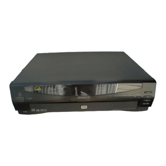
DVD VCD CD PLAYER
DV-4050-B
DVF-R6030-B
SERVICE MANUAL
Knob
(K29-7801-13)
STANDBY
STANDBY
POWER
DISC SKIP
ON/STANDBY
ON/STANDBY
5
D I S C
changer
Knob
(K29-7804-13)
Metallic cabinet
Oscillating module
(A01-3776-01)
(W02-2732-05)
COAXIAL OPTICAL
DIGITAL OUTPUT
( PCM/BIT STREAM )
Pin jack
(E63-1127-05)
In compliance with Federal Regulations, following are repro-
duction of labels on, or inside the porduct relating to laser
product safety.
KENWOOD-Crop. certifies this equipment conforms to DHHS
Regulations No.21 CFR 1040. 10, Chapter 1, subchapter J.
DANGER : Laser radiation when open and interlock
defeated.
AVOID DIRECT EXPOSURE TO BEAM.
VIRTUAL
SURROUND
Pin jack
(E63-1159-05)
S VIDEO
Y
Cb
OUTPUT
COMPONENT VIDEO OUTPUT
Cylindrical receptacle
(E56-0032-05)
Caution : No connection of ground line if disassemble
© 2000-9/B51-5661-00 (K/K) 1399
Front glass
(B10-3610-02)
1
2
3
DISC
DISC
DISC
Knob
(K29-7822-13)
Pin jack
(E63-1157-05)
Pin jack
(E63-1161-05)
1
L
R
2
1
2
Cr
VIDEO
OUTPUT
LINE OUTPUT
SUB WOOFER
Pin jack
(E63-1162-05)
* Refer to parts list on page17.
the unit. Please connect the ground line on
rear panel, PCBs, Chassis and some others.
Panel *
(A60-)
3
OPEN/CLOSE
4
5
0
DISC
DISC
8
7
4 ¢
Knob
(K29-7823-13)
AC power cord *
(E30-)
AC power cord bushing
(J42-0083-05)
70%
Advertisement

Related Manuals for Kenwood DV-4050-B


Summary of Contents for Kenwood DV-4050-B
- Page 1 Please connect the ground line on product safety. rear panel, PCBs, Chassis and some others. KENWOOD-Crop. certifies this equipment conforms to DHHS Regulations No.21 CFR 1040. 10, Chapter 1, subchapter J. DANGER : Laser radiation when open and interlock defeated.
-
Page 2: Table Of Contents
PC BOARD..............7 SPECIFICATIONS ............20 Note: Please contact our KENWOOD Service Department in your side if you want the information; Microprocessor(MN101C35D) ports explanation and full (previous) format parts list on this model. You can be available them by internet from us. -
Page 3: Disassembly For Repair
DV-4050-B/DVF-R6030-B DISASSEMBLY FOR REPAIR 1. How to Remove Tray HOOK ( 1. Remove the front panel and flexible cable. Disassemble the X25 and power supply pcb with sub chassis if it is a difficult. 2. Push and hold the lever( )to clockwise and pull barely out the tray to frontwards( ) where the hook of tray( ) meets with guide( ). - Page 4 DV-4050-B/DVF-R6030-B DISASSEMBLY FOR REPAIR 3. How to Remove Clamper Ass'y 4. How to Disassemble Clamper Ass'y 1. Remove screws. Clamper weight Spacer Magnet Clamper 6. Tangential and Tilt Adjustment 1. Turn the power on with pressing the DISC 1 key.
-
Page 5: Circuit Description
DV-4050-B/DVF-R6030-B CIRCUIT DESCRIPTION Microprocessor pin description : MN101C35D(X14,IC1) Pin No. Pin Name Description Serial output for system communication. STATUS Serial input for system communication. DSPCLK Serial clock for system communication. DATA Data signal output to buffer. Strobe signal output to buffer. -
Page 6: Adjustment
DV-4050-B/DVF-R6030-B ADJUSTMENT INPUT ALIGNMENT ALIGNMENT ITEM OUTPUT SETTING FIG. SETTING POINT Connect the oscilloscope to Y-signal = 100% COLOR BRIGHTNESS Y output with 75-ohms FIG.1. BAR DISC 1000mV±30mV resistor Connect the oscilloscope to Chrom-signal = 100% COLOR CHROM LEVEL COMPOSIT output with 75- FIG.2. -
Page 7: Pc Board
PC BOARD(Component side view) X25-6380-10 (J70-1428-11) C200 D201 C201 R200 R173 C202 R156 W110 O I G R201 R202 Q200 Q118 C134 C136 (Cr) C101 C102 (Cb) Q100 X13-7770-10 (J70-1426-12) W126 C120 R102 R101 R105 R103 C119 R106 R104 W143 C104 C117 C103... - Page 8 (X25-6380-10) 12 11 10 9 8 7 6 5 4 3 8 7 6 5 4 3 2 1 1 2 3 4 5 6 7 8 9 10 11 12 13 14 15 16 17 18 19 20 21 22 23 24 25 R173 R120...
- Page 9 : 1SS133 or 4.7V HSS104A 2 Cb OUTPUT DRIVER : RD6.8ES(B) or (Cr SIGNAL) MTZJ6.8(B) D200 : RD4.7ES(B) or MTZJ4.7(B) 47u25 D201 : RD30ES(B) or 3 Cr MTZJ30(B) DV-4050-B/DVF-R6030-B DIGITAL LINE SIGNAL LINE GND LINE B LINE B LINE Y22-8320-10 DV-4050-B/DVF-R6030 (1/2)
-
Page 10: Parts List
CAUTION: For continued safety, replace safety critical components only with manufacturer's recommended parts (refer to The DC voltage is an actual reading measured with a high imped- DV-4050-B/DVF-R6030-B parts list). indicates safety critical components. For continued protection against risk of fire, replace only with same type ance type voltmeter. - Page 11 (17P) (14P) (X13-7770-10) (21P) 3x10 (BLK) : N89-3010-45 : N09-5214-05 : N82-2006-46 : N35-2604-46 DV-4050/DV-4900...
- Page 12 SUB WOOFER VIDEO S VIDEO OPTICAL COAXIAL OUTPUT OUTPUT OUTPUT COMPONENT VIDEO OUTPUT DIGITAL OUTPUT (X25- 6380) (14P) : N09-1445-05 (25P) : N09-5213-05 (21P) : N89-3006-46 2.6x6 (BLK) : N82-2606-45 (17P) 2.6x8 : N82-2608-46 3x8 (BLK) : N89-3008-45 : N89-3008-46 3x10 : N89-3010-45 POWER...
- Page 13 Ref. No Description Parts No. Parts No. Description Ref. No marks ress Parts nation ress Parts nation marks ✽ K29-7804-13 KNOB DV-4050-B(K), DVF-R6030-B(Y) ✽ K29-7822-13 KNOB 5-DISC ✽ K29-7823-13 KNOB PLAY ✽ A01-3776-01 METALLIC CABINET ✽ A29-1113-22 PANEL TRAY ✽...
- Page 14 ✽ New Parts ✽ New Parts Parts without Parts No. are not supplied. Parts without Parts No. are not supplied. Les articles non mentionnes dans le Parts No. ne sont pas fournis. Les articles non mentionnes dans le Parts No. ne sont pas fournis. Teile ohne Parts No.
- Page 15 ✽ New Parts ✽ New Parts Parts without Parts No. are not supplied. Parts without Parts No. are not supplied. Les articles non mentionnes dans le Parts No. ne sont pas fournis. Les articles non mentionnes dans le Parts No. ne sont pas fournis. Teile ohne Parts No.
-
Page 16: Specifications
DV-4050-B/DVF-R6030-B SPECIFICATIONS [Audio section] [Laser] Frequency response Wave length ..........660 nm - 676 nm Sampling frequency; 44.1 kHz (CD only)...4 Hz ~ 20 kHz Laser power class ........Class 2 (IEC) [General] Sampling frequency; 48 kHz ......4 Hz ~ 22 kHz Sampling frequency;... -
Page 17: Schematic Diagram
Av. Moema, 170-17˚, Andar-Cobertura “B”, Ed. Maximum Service Center, 04077-020 Moema, São Paulo-SP-Brasil KENWOOD ELECTRONICS U.K. LIMITED KENWOOD House, Dwight Road, Watford, Herts., WD1 8EB., United Kingdom KENWOOD ELECTRONICS BELGUM N.V. Meachelsesteenweg 418, B-1930 Zaventem, Belgium KENWOOD ELECTRONICS DEUTSCHLAND GMBH Rembrücker Str.