Table of Contents
Advertisement
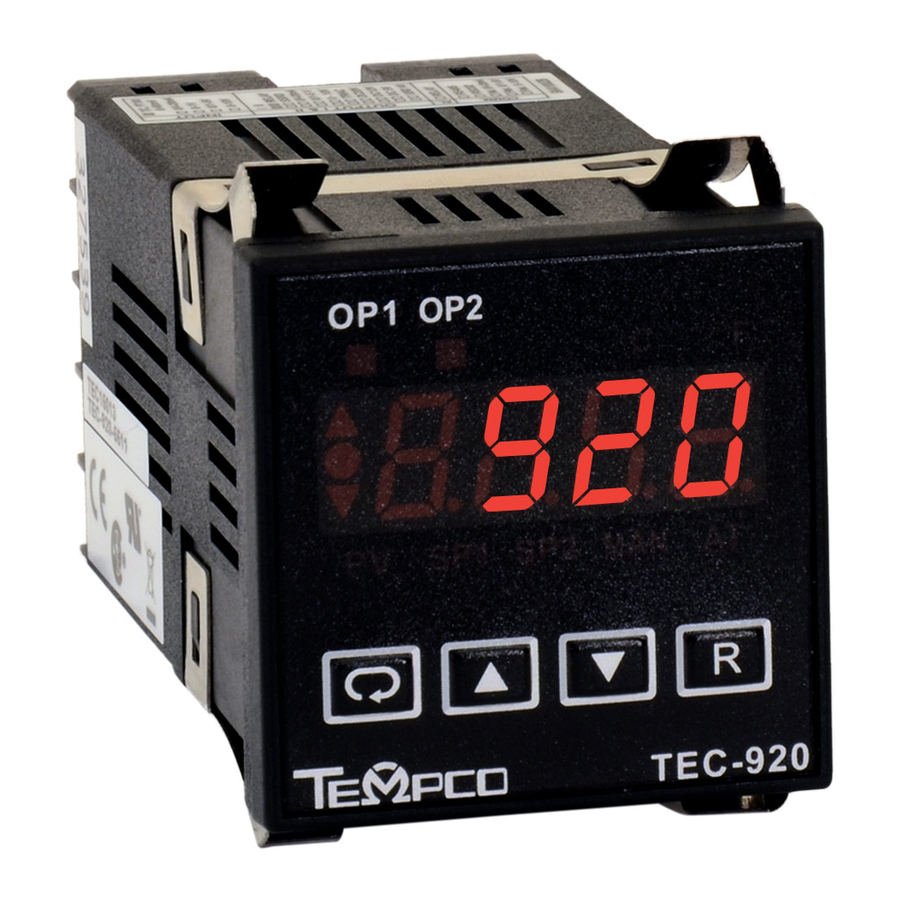
TEC-220 and TEC-920
Auto-Tune Fuzzy / PID Process
Temperature Controller
Serving Industry Since 1972
Instruction Manual
Agency Approvals
TEMPCO Electric Heater Corporation
607 N. Central Avenue • Wood Dale, IL 60191-1452 USA
Tel: 630-350-2252 • Toll Free: 800-323-6859
Fax: 630-350-0232 • E-mail: info@tempco.com
Web: www.tempco.com
Manual TEC-220/920 Revision 9/2016
Advertisement
Table of Contents

Related Manuals for Tempco tec-220


Summary of Contents for Tempco tec-220
- Page 1 Auto-Tune Fuzzy / PID Process Temperature Controller Agency Approvals TEMPCO Electric Heater Corporation 607 N. Central Avenue • Wood Dale, IL 60191-1452 USA Tel: 630-350-2252 • Toll Free: 800-323-6859 Serving Industry Since 1972 Fax: 630-350-0232 • E-mail: info@tempco.com Web: www.tempco.com Manual TEC-220/920 Revision 9/2016...
- Page 2 NOTES...
-
Page 3: Table Of Contents
Figure 2.2 Lead Termination for TEC-920 ... . . 7 Figure 2.3 Lead Termination for TEC-220 ... . . 7 1-6 Parameter Descriptions . - Page 4 NOTES...
-
Page 5: Chapter 1 Overview
Fuzzy technology. The TEC-220 is a 1/32 DIN size panel mount controller. The TEC-920 is a 1/16 DIN size panel mount controller. These units are powered by 11–26 or 90–250 VDC/VAC 50/60 Hz supply, incorporating a 2 Amp control relay output as a standard. -
Page 6: Ordering Code
1–2 Ordering Code Figure 1.2 Programming Port Overview 1–3 Programming Port A special connector can be used to connect the programming port to a PC for automatic configuration. The programming port is used for off- line automatic setup and testing proce- dures only. -
Page 7: Keys And Displays
Table 1.1 Display Form of Characters RESET KEY: for TEC-920, This key is used to: for TEC-220 1. Revert the display to show the process value. 2. Reset the latching alarm, once the alarm condi- tion is removed. 3. Stop the manual control mode, auto-tuning mode, and calibration mode. -
Page 8: Menu Overview
1–5 Menu Overview... -
Page 9: Parameter Descriptions
1–6 Parameter Descriptions... - Page 10 1–6 Parameter Descriptions, continued…...
-
Page 11: Chapter 2 Installation
2–3 Wiring Precautions Note: All model TEC-220 controls are supplied with both mounting clamps and mounting screws. The • Before wiring, verify the correct model number and options on the label. -
Page 12: Power Wiring
Wiring, continued… This equipment is designed for installation in an 2–4 Power Wiring enclosure which provides adequate protection against The controller is designed to operate at 11–26VAC/VDC electric shock. Metal enclosures must be connected to or 90–250VAC. Check that the input voltage corresponds earth ground. -
Page 13: Drive Load
Control Output Wiring, continued… Load 120V / 240V Mains Supply Internal Circuit 30mA/5V Pulsed Voltage Figure 2.10 Output 1 Pulsed Voltage to Drive SSR... -
Page 14: Alarm Wiring
2–8 Alarm Wiring 2–9 Data Communication If you use a conventional 9-pin RS-232 cable instead of TEC99014, the cable must be modified according to the following circuit diagram. -
Page 15: Chapter 3 Programming
Chapter 3 Programming Press for 5 seconds and release to enter the setup menu. 3–2 Signal Input Press and release to select the desired parameter. The display INPT: Selects the sensor type or signal type for signal input. indicates the parameter symbol. Press to view or Range: (thermocouple) Type J, K, T, E, B, R, S, N, L adjust the value of the selected parameter. - Page 16 Control Outputs, continued… Heat only ON-OFF control: Select REVR for OUT1. Set PB Cool only control: ON-OFF control, P (PD) control, and PID (Proportional Band) to 0. O1HY is used to adjust dead band for control can be used for cool control. Set OUT1 to DIRT (direct ON-OFF control.
-
Page 17: Alarm
3.3 & 3.4 Alarm Figures 3–4 Alarm Output 2 can be set as an alarm output. There are six types of alarm functions and one dwell timer that can be selected, and four kinds of alarm modes (ALMD) are available for each alarm function. -
Page 18: Configuring The Display
3–5 Configuring the Display The TEC-220 can be configured to display the process value by selecting PV for DISP or to display the set point value by select- ing SP1 for DISP. If LOCK is set to NONE, OUT2 is set to DEHI, and DISP is set SEL1=SHIF, SEL2=ADDR. -
Page 19: Pv Shift
3–8 PV Shift In certain applications it is desirable to shift the controller display value from its actual value. This can easily be accomplished by using the PV shift function. The SHIF function will alter PV only. Here is an Example: A process is equipped with a heater, a sensor, and a subject to be warmed up. -
Page 20: Auto-Tuning
3. Press several times until appears on the display (for TEC-220), or an AT indicator on lower-right of screen is lit (for TEC-920). 4. Press and hold for at least 5 seconds. The AT indicator (for TEC-920) or the display (for TEC-220) will begin to flash indicating the auto-tuning procedure has begun. -
Page 21: Manual Control
5 seconds or until the MAN indicator (for TEC-920) or the dis- scale and high scale values of retransmission. play (for TEC-220) begins to flash. The controller is now in man- The TEC-920 does not have this feature. ual control mode. - Page 22 NOTES...
-
Page 23: Chapter 4 Applications
Chapter 4 Applications 4–1 Heat Only Control with Dwell Timer An oven is designed to dry products at 150°C for 30 minutes and then stay unpowered for another batch. A TEC-920 equipped with dwell timer is used for this purpose. The system diagram is shown at right: To achieve this function, set the following parame- ters in the setup menu:... -
Page 24: Heat-Cool Control
4–3 Heat-Cool Control An injection mold is required to be controlled at 120°C to ensure a consistent quality for the parts. An oil pipe is buried in the mold. Since plastics are injected at a higher temperature (e.g., 250°C), the circulation oil needs to be cooled as its temperature rises. -
Page 25: Chapter 5 Calibration
Chapter 5 Calibration Do not proceed through this section unless there is a def- Manual Calibration Procedures inite need to recalibrate the controller. If you recalibrate, • Perform step 1 to enter calibration mode. all previous calibration data will be lost. Do not attempt recali- bration unless you have the appropriate calibration equipment. - Page 26 Manual Calibration Procedures, continued… Set up the equipment according to the diagram above for calibrating the Step 6. cold junction compensation. Note that a K type thermocouple must be used. The 525A calibrator is configured as K type thermocouple output with internal compensation.
-
Page 27: Chapter 6 Specifications
Chapter 6 Specifications Power 90–250VAC, 47–63 Hz, 10VA, 5W maximum 11–26VAC/VDC, 10VA, 5W maximum Input 18 bits 5 times/second Resolution: -2VDC minimum, 12VDC maximum Sampling rate: (1 minute for mA input) Maximum rating: ±1.5uV/°C for all inputs except mA input Temperature effect: ±3.0uV/°C for mA input T/C: 0.2uV/ohm... -
Page 28: Analog Retransmission
Stop bit: 1 or 2 bits Moldings: Flame retardant polycarbonate Communication buffer: 160 bytes Dimensions: TEC-220 — 1-3/64" (26.5 mm) H × 2" (50 mm) W Analog Retransmission × 4-3/8" (110.5 mm) D Output Signal: 4-20 mA, 0-20 mA, 0-5V, 1-5V, 0-10V Depth behind panel: 3-7/8"... -
Page 29: Chapter 7 Modbus Communications
Chapter 7 Modbus Communications This chapter specifies the Modbus Communications protocol as RS-232 or RS-485 interface module is installed. Only RTU mode is supported. Data is transmitted as eight-bit binary bytes with 1 start bit, 1 stop bit and optional parity checking (None, Even or Odd). -
Page 30: Exception Responses
7-2 Exception Responses If the controller receives a message which contains a corrupted character (parity check error, framing error etc.), or if the CRC16 check fails, the controller ignores the message. However, if the controller receives a syntactically correct message which contains an illegal value, it will send an exception response, consisting of five bytes as follows: slave address +offset function code + exception code + CRC16 Hi +CRC16 Lo Where the offset function code is obtained by adding the function code with 128 (ie. - Page 31 Register Parameter Parameter Scale Scale Notes Address Notation High ALFN Alarm Function 65535 REHI Retransmission high scale value ALMD Alarm operation mode 65535 ALHY Alarm hysteresis ALFT Alarm failure transfer 65535 COMM Communication function 65535 ADDR Address 65535 BAUD Baud rate 65535 DATA Data bit count...
-
Page 32: Data Conversion
H’030X = Manual control mode The alarm status is shown in MV2 instead of H’040X = Failure mode MODE for models TEC-220 and TEC-920. *3 The PROG Code is defined in the following table Model No. TEC-9100 TEC-8100 TEC-4100 TEC-7100... -
Page 33: Communication Examples
7-5 Communication Examples: Example 1: Download the default values via the programming port The programming port can perform Modbus communications regardless of the incorrect setup values of address, baud, parity, stop bit, etc. It is especially useful during the first time configuration for the controller. The host must be set with 9600 baud rate, 8 data bits, even parity and 1 stop bit. -
Page 34: Error Codes
A–1 Error Codes Table A.1 Error Codes and Corrective Actions... -
Page 35: Warranty
Tempco Electric Heater Corporation is pleased to offer sugges- No product returns can be accepted without a completed Return tions on the use of its products. However, Tempco makes no war- Material Authorization (RMA) form. ranties or representations of any sort regarding the fitness for use, or the application of its products by the Purchaser. - Page 36 The Electric Heating Element, Temperature Controls and Temperature Sensors Handbook REQUEST YOUR FREE 960 PAGE COPY TODAY! Call (800-323-6859) or E-mail (info@tempco.com) Specify Print Edition, CD-ROM or Both Serving Industry Since 1972 Experience the Advantages of our Diverse and Innovative Products TEMPCO Electric Heater Corporation 607 N.