Onkyo TX-NR3008 Instruction Manual
Onkyo av receiver user manual
Hide thumbs
Also See for TX-NR3008:
- Specifications (2 pages) ,
- Quick setup (2 pages) ,
- Firmware update manual (10 pages)
Table of Contents
Advertisement
Quick Links
AV Receiver
TX-NR5008
TX-NR3008
Instruction Manual
Thank you for purchasing an Onkyo AV Receiver.
Please read this manual thoroughly before making
connections and plugging in the unit.
Following the instructions in this manual will enable
you to obtain optimum performance and listening
enjoyment from your new AV Receiver.
Please retain this manual for future reference.
Contents
Introduction ...................................2
Connections.................................13
Turning On & Basic Operations ......27
Advanced Operations .................46
Controlling iPod & Other
Components............................86
Others...........................................99
E
n
Advertisement
Table of Contents

Related Manuals for Onkyo TX-NR3008


Summary of Contents for Onkyo TX-NR3008
- Page 1 AV Receiver TX-NR5008 TX-NR3008 Instruction Manual Thank you for purchasing an Onkyo AV Receiver. Please read this manual thoroughly before making connections and plugging in the unit. Following the instructions in this manual will enable you to obtain optimum performance and listening enjoyment from your new AV Receiver.
-
Page 2: Introduction
Introduction WARNING: TO REDUCE THE RISK OF FIRE OR ELECTRIC SHOCK, DO NOT EXPOSE THIS APPARATUS TO RAIN OR MOISTURE. CAUTION: TO REDUCE THE RISK OF ELECTRIC SHOCK, DO NOT REMOVE COVER (OR BACK). NO USER-SERVICEABLE PARTS INSIDE. REFER SERVICING QUALIFIED PERSONNEL. -
Page 3: Precautions
If water or any other liquid gets inside this unit, have it checked by your Onkyo dealer. 8. Handling Notes • If you need to transport this unit, use the original packaging to pack it how it was when you originally bought it. -
Page 4: Supplied Accessories
We, ONKYO EUROPE ELECTRONICS GmbH LIEGNITZERSTRASSE 6, 82194 GROEBENZELL, GERMANY declare in own responsibility, that the ONKYO product described in this instruction manual is in compliance with the corresponding technical standards such as EN60065, EN55013, EN55020 and EN61000-3-2, -3-3. GROEBENZELL, GERMANY... -
Page 5: Table Of Contents
Looking up for Remote Control Code ... 91 Entering Remote Control Codes... 93 Remote Control Codes for Onkyo Components Connected via u ... 93 Resetting REMOTE MODE Buttons ... 94 Resetting the Remote Controller ... 94 Controlling Other Components ... 94 Activities Setup ... -
Page 6: Features
• 8 HDMI • Onkyo p for System Control • (TX-NR5008) 7 Digital Inputs (4 Optical/3 Coaxial) • (TX-NR3008) 6 Digital Inputs (3 Optical/3 Coaxial) • Component Video Switching (3 Inputs/1 Output) • Universal Port for the Optional Dock for iPod Radio™... - Page 7 HD Radio™ and the HD Radio Ready logo are proprietary trademarks of iBiquity Digital Corporation. To receive HD Radio broadcasts, you must install an Onkyo UP-HT1 HD Radio tuner module (sold separately). In Europe, using banana plugs to connect speakers to an audio amplifier is prohibited.
-
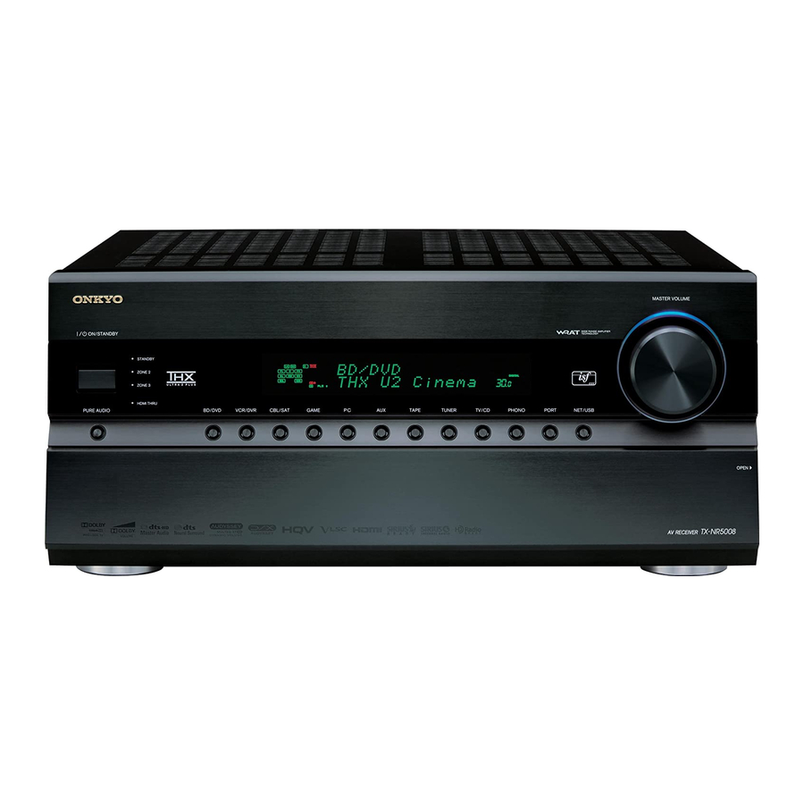
Page 8: Front & Rear Panels
Front & Rear Panels Front Panel The actual front panel has various logos printed on it. They are not shown here for clarity. The page numbers in parentheses show where you can find the main explanation for each item. a ON/STANDBY button (➔... -
Page 9: Display
The page numbers in parentheses show where you can find the main explanation for each item. k PHONES jack (➔ l ZONE 2, ZONE 3 and OFF buttons m TONE button (➔ 66, 84) n LEVEL button (➔ o MONITOR OUT button (➔... -
Page 10: Rear Panel
Rear Panel Illustration is based on TX-NR5008. a UNIVERSAL PORT jack b IR IN and OUT jacks c DIGITAL IN COAXIAL and OPTICAL jacks d USB port (TX-NR5008) e ETHERNET port f u REMOTE CONTROL jack g RS232 terminal Terminal for control. h HDMI IN and HDMI output (HDMI OUT MAIN and HDMI OUT SUB) jacks i MONITOR OUT V and S jacks... -
Page 11: Remote Controller
Controlling the AV Receiver To control the AV receiver, press RECEIVER to select Receiver mode. You can also use the remote controller to control Onkyo Blu-ray Disc/DVD player, CD player and other components. See “Entering Remote Control Codes” for more details (➔... -
Page 12: About Home Theater
With Blu-ray Discs or DVDs, you can enjoy DTS and Dolby Digital. With analog or digital TV, you can enjoy Dolby Pro Logic IIx, DTS Neo:6, or Onkyo’s original DSP lis- tening modes. -
Page 13: Connections
Connections Connecting the AV Receiver Connecting Your Speakers About Speakers A and Speakers B Installing Speakers A and Speakers B allows you to enjoy up to 7.2-channel surround-sound playback from each speaker configuration. Each configuration has its own pair of stereo front speakers and can use the same subwoofer, center, sur- round, and surround back speakers, as required. - Page 14 Speaker Configuration The following table indicates the channels you should use depending on the number of speakers that you have. For 9.2-channel surround-sound playback, you need 9 speakers and 2 powered subwoofers. Number of 2 3 4 5 6 7 7 7 8 8 9 9 9 10 11 speakers Front speakers ✔...
- Page 15 Connecting the Speaker Cables Screw-type speaker terminals Strip 1/2" to 5/8" (12 to 15 mm) of insulation from the ends of the speaker cables, and twist the bare wires tightly, as shown. Using Banana Plugs (North American models) • If you are using banana plugs, tighten the speaker terminal before inserting the banana plug. •...
- Page 16 ■ 7.2-channel Playback with Speakers A or Speakers B The following illustration shows which speaker should be connected to each pair of terminals for up to 7.2-channel play- back with Speakers A or Speakers B. If you’re using only one surround back speaker, connect it to the SURR BACK/ ZONE 3 L terminal.
- Page 17 Using Dipole Speakers You can use dipole speakers for the surround and surround back speakers. Dipole speakers output the same sound in two directions. Dipole speakers typically have an arrow printed on them to indicate how they should be positioned. The surround dipole speakers should be positioned so that their arrows point toward the TV/screen, while the surround back dipole speak- ers should be positioned so that their arrows point toward...
- Page 18 Bridging the Front Speakers A The FRONT L/R and SURR BACK/ZONE 3 L/R terminal posts can be used with front speakers and surround back speak- ers respectively, or bridged together to provide almost double the output power for the front speakers A. •...
- Page 19 Bridging the Front Speakers B The FRONT WIDE/ZONE 2 L/R and SURR BACK/ ZONE 3 L/R terminal posts can be used with front wide speakers and surround back speakers respectively, or bridged together to provide almost double the output power for the front speakers B.
-
Page 20: About Av Connections
About AV Connections Connected image with AV components HDMI cable AV receiver Blu-ray Disc/ DVD player TV, projector, etc. • Before making any AV connections, read the manuals supplied with your AV components. • Don’t connect the power cord until you’ve completed and double-checked all AV connections. •... -
Page 21: Connecting Your Components With Hdmi
Connecting Your Components with HDMI VCR or DVD recorder/Digital Video Recorder Game console Personal computer Satellite, cable, set-top box, etc. Connect your components to the appropriate jacks. The default input assignments are shown below. ✔: Assignment can be changed (➔ 48 to 49). -
Page 22: Connecting Your Components
Connecting Your Components Front Rear Connect your components to the appropriate jacks. The default input assignments are shown below. ✔: Assignment can be changed Jack AUX INPUT VIDEO AUDIO L/R DIGITAL COMPONENT IN 1 (BD/DVD) VIDEO IN 2 (CBL/SAT) IN 3 (GAME) MONITOR OUT DIGITAL COAXIAL... -
Page 23: Connecting Onkyo U Components
AV receiver. The other jack is for connecting addi- tional u-capable components. • Connect only Onkyo components to u jacks. Connecting other manufacturer’s components may cause a malfunction. • Some components may not support all u functions. Refer to the manuals supplied with your other Onkyo components. -
Page 24: Connecting Antenna
Connecting Antenna This section explains how to connect the supplied indoor FM antenna and AM loop antenna. The AV receiver won’t pick up any radio signals without any antenna connected, so you must connect the antenna to use the tuner. (North American models) Insert the plug fully... -
Page 25: Which Connections Should I Use
Which Connections Should I Use? The AV receiver supports several connection formats for compatibility with a wide range of AV equipment. The format you choose will depend on the formats supported by your components. Use the following sections as a guide. Video Connection Formats Video component can be connected by using any one of the following video connection formats: composite video, S-Video, PC IN (Analog RGB), component video or HDMI, the latter offering the best picture quality. - Page 26 ■ “Monitor Out” setting set to “Analog” Video input signals flow through the AV receiver as shown, with composite video, S-Video and PC IN (Analog RGB) sources being upconverted for the component video output. Use this setting if you connect the AV receiver’s COMPONENT VIDEO MONITOR OUT to your TV.
-
Page 27: Turning On & Basic Operations
Turning On & Basic Operations Turning On/Off the AV Receiver (North American models) ON/STANDBY STANDBY indicator Turning On (European and Asian models) Set POWER to the ON position ( ) on the front panel. The AV receiver enters Standby mode, and the STANDBY indicator comes on. Press ON/STANDBY on the front panel. -
Page 28: Basic Operations
Basic Operations This manual describes the procedure using the remote controller unless otherwise specified. Selecting the Language Used for the Onscreen Setup Menus You can determine the language used for the onscreen setup menus. See “Language” in the “OSD Setup” 63). -
Page 29: Muting The Av Receiver
Muting the AV Receiver You can temporarily mute the output of the AV receiver. Press RECEIVER followed by MUTING. The output is muted and the MUTING indicator flashes on the display. • To unmute, press MUTING again or adjust the volume. •... -
Page 30: Using The Home Menu
Using the Home Menu The Home menu provides you quick access to frequently used menus without having to go through the long stan- dard menu. This menu enables you to change settings and view the current information. Press RECEIVER followed by HOME. The following information will be superimposed on the TV screen. -
Page 31: Changing The Input Display
Changing the Input Display When you connect an u-capable Onkyo component, you must configure the input display so that u can work properly. This setting can be done only from the front panel. Press TAPE, GAME or VCR/DVR so that “TAPE”, “GAME”... -
Page 32: Audyssey Multeq ® Xt32 Room Correction And Speaker Setup
Turning Off the Components Press ALL OFF. The playback component assigned to the last- pressed ACTIVITIES, the AV receiver, and the TV turn off. When the last-pressed ACTIVITIES is MY MUSIC, the TV will not turn off. Changing the Playback Components Assigned to ACTIVITIES You can change the playback components assigned to the ACTIVITIES of Easy Macro mode using the following... - Page 33 c a b : Listening area a to h: Listening position Note • Make the room as quiet as possible. Background noise and Radio Frequency Interference (RFI) can disrupt the room measure- ments. Close windows, televisions, radios, air conditioners, flu- orescent lights, home appliances, light dimmers, or other devices.
- Page 34 • Writing Error! This message appears if saving fails. Try saving again. If this message appears after 2 or 3 attempts, contact your Onkyo dealer. • Speaker Detect Error This message appears if a speaker is not detected. “No” means that no speaker was detected.
-
Page 35: Listening To The Radio
Listening to the Radio This section describes the procedure using the but- tons on the front panel unless otherwise specified. Using the Tuner With the built-in tuner you can enjoy AM and FM radio stations. You can store your favorite stations as presets for quick selection. -
Page 36: Presetting Fm/Am Stations
Presetting FM/AM Stations You can store a combination of up to 40 of your favorite FM/AM radio stations as presets. Tune into the FM/AM station that you want to store as a preset. See the previous section. Press MEMORY. The preset number flashes. (Actual display depends on the country.) While the preset number is flashing (about 8 sec- onds), use PRESET e/r to select a preset from 1... - Page 37 Finding Stations by Type (PTY) You can search for radio stations by type. Press RT/PTY/TP twice. The current program type appears on the display. Use PRESET e/r to select the type of program you want. See the table shown later in this chapter. To start the search, press ENTER.
-
Page 38: Recording
Recording This section explains how to record the selected input source to a component with recording capability, and how to record audio and video from different sources. Connecting a Recording Component Cassette, CDR, MD, VCR, DVD recorder Note • The AV receiver must be turned on for recording. Recording is not possible while it’s in Standby mode. -
Page 39: Using The Listening Modes
Using the Listening Modes Selecting Listening Modes See “About Listening Modes” for detailed information about the listening modes Listening Mode Buttons Press RECEIVER first. MUSIC MOVIE/TV MOVIE/TV button This button selects the listening modes intended for use with movies and TV. MUSIC button This button selects the listening modes intended for use with music. -
Page 40: About Listening Modes
About Listening Modes The AV receiver’s listening modes can transform your listening room into a movie theater or concert hall, with high fidel- ity and stunning surround sound. Explanatory Notes SP LAYOUT LISTENING MODE ■ Input Source The following audio formats are supported by the listening mode. This is mono (monophonic) sound. -
Page 41: Listening Modes
Listening Modes Listening Mode Description Pure Audio In this mode, the display and video circuitry are turned off, minimizing pos- sible noise sources for the ultimate in high-fidelity audio reproduction. (As P u r e A u d i o the video circuitry is turned off, only video signals input through HDMI input can be output from an HDMI output(s). - Page 42 Listening Mode Description DTS-HD High (Continued from the previous page.) Resolution Audio D T S – H D H R DTS-HD Master Audio D T S – H D M S T R DTS Express D T S E x p r e s s D S D DTS 96/24 This mode is for use with DTS 96/24 sources.
- Page 43 Listening Mode Description Founded by George Lucas, THX develops stringent standards that ensure movies are reproduced in movie theaters and home theaters just as the direc- T H X C i n e m a tor intended. THX Modes carefully optimize the tonal and spatial character- istics of the soundtrack for reproduction in the home-theater environment.
- Page 44 Listening Mode Description Neural Surround This mode employs psychoacoustic frequency domain processing, which allows delivery of a more detailed sound stage, with superior channel separa- N R L S u r r o u n d tion and localization of audio elements. The Neural Surround modes can expand any 2-channel stereo source for 5.1- or 7.1-channel playback, respec- N R L e m a...
- Page 45 Onkyo-Original DSP Listening Modes Listening Mode Description Orchestra Suitable for classical or operatic music, this mode emphasizes the surround channels in order to widen the stereo image, and simulates the natural rever- O r c h e s t r a beration of a large hall.
-
Page 46: Advanced Operations
Advanced Operations Advanced Setup On-screen Setup Menus This manual describes the procedure using the remote controller unless otherwise specified. MENU 1. Input/Output Assign 2. Speaker Setup 3. Audio Adjust 4. Source Setup 5. Listening Mode Preset 6. Miscellaneous 7. Hardware Setup 8. -
Page 47: Input/Output Assign
Explanatory Notes Main Menu Speaker Setup ■ Subwoofer 1ch: Audio signal is outputted from SW1 jack only. 2ch: Audio signal is outputted from SW1 and SW2 jacks. a Menu selection b Setting target c Setting options (default setting underlined) Input/Output Assign Main Menu Input/Output Assign Monitor Out... -
Page 48: Hdmi Input
■ Resolution You can specify the output resolution for the HDMI and COMPONENT VIDEO MONITOR OUT and have the AV receiver upconvert the picture resolution as neces- sary to match the resolution supported by your TV. Through Select this to pass video through the AV receiver at the same resolution and with no conversion. -
Page 49: Component Video Input
Note • For composite video, S-Video, and component video upconver- sion for the HDMI output, the “Monitor Out” setting must be set to other than “Analog” (➔ 47), and the “HDMI Input” set- ting must be set to “- - - - -”. See “Video Connection Formats” for more information on video signal flow and upconversion (➔... -
Page 50: Speaker Setup
Digital Audio Input If you connect a component to a digital audio input, you must assign that input to an input selector. For example, if you connect your CD player to the OPTICAL IN 1, you must assign “OPT 1” to the “TV/CD” input selector. Here are the default assignments. - Page 51 ■ Speaker Impedance 4ohms: Select if the impedance of any speaker is 4 ohms or more but less than 6. 6ohms: Select if the impedances of all speakers are between 6 and 16 ohms. Note • When bridging is used, “Speaker Impedance” setting is fixed at “8ohms”.
-
Page 52: Speaker Distance
■ Front (Setting Speakers A and Speakers B) Full Band 40Hz to 80Hz(THX) to 100Hz, 120Hz, 150Hz, 200Hz Note • If the “Subwoofer” setting is set to “No”, the “Front” setting is fixed at “Full Band”. ■ Center , Surround , Surround Back Full Band 40Hz to 80Hz(THX) to 100Hz, 120Hz, 150Hz,... -
Page 53: Equalizer Settings
■ Left, Front Wide Left, Front High Left, Center, Front High Right, Front Wide Right, Right, Surround Right, Surround Back Right, Surround Back Left, Surround Left, Subwoofer 1, Subwoofer 2 Specify the distance from the each speaker to your lis- tening position. -
Page 54: Audio Adjust
THX Audio Setup With the “Surr Back Speaker Spacing” setting, you can specify the distance between your surround back speakers. This setting is used by Speakers A and Speakers B. If you’re using a THX-certified subwoofer, set the “THX Ultra2/Select2 Subwoofer” setting to “Yes”. You can then apply THX’s Boundary Gain Compensation (BGC) to compensate the perceived exaggeration of low frequen- cies for listeners sitting very close to a room boundary... - Page 55 Input Channel Left + Right: Both the left and right channels are output. Left: Only the left channel is output. Right: Only the right channel is output. Output Speaker Center: Mono audio is output by the center speaker. Left / Right: Mono audio is output by the front left and right speakers.
-
Page 56: Audyssey Dsx
■ Volume Leveler Off: Volume Leveler off. Low: Low Compression Mode becomes active. Mid: Medium Compression Mode becomes active. High: High Compression Mode becomes active. This set- ting affects volume the most, causing all sounds to be of equal loudness. “Volume Leveler”... -
Page 57: Source Setup
Direct ■ Analog Subwoofer Off: Analog audio signals (bass signals) are not output. Analog audio signals (bass signals) are output. This setting determines whether or not analog audio sig- nals (bass signals) are output from front speakers when the Pure Audio or Direct listening mode is selected. Note •... - Page 58 ■ Dynamic Volume Off: Audyssey Dynamic Volume Light: Light Compression Mode becomes active. Medium: Medium Compression Mode becomes active. Heavy: Heavy Compression Mode becomes active. This set- ting affects volume the most, causing all sounds to be of equal loudness. Note •...
-
Page 59: Name Edit
IntelliVolume ■ IntelliVolume –12dB to 0dB to +12dB in 1 dB steps. With IntelliVolume, you can set the input level for each input selector individually. This is useful if one of your source components is louder or quieter than the others. Use e/r to set the level. -
Page 60: Picture Adjust
Accordingly, Onkyo recommends that setup and calibration be per- formed by an ISF Certified installation technician. ■... - Page 61 ■ Mosquito NR *2*3*4*6 Off: Mosquito noise reduction off. Low: Low mosquito noise reduction. Mid: Medium mosquito noise reduction. High: High mosquito noise reduction. With Mosquito Noise Reduction, you can remove the shimmering or haziness that sometimes appears around objects in the picture. Mosquito noise can be an issue with overly compressed MPEG content.
-
Page 62: Listening Mode Preset
■ Blue Contrast *2*4 –50 to 0 to +50 With this setting you can adjust blue contrast. “–50” is the least. “+50” is the greatest. This procedure can also be performed on the remote controller by using the Home menu (➔... -
Page 63: Miscellaneous
Miscellaneous Main menu Miscellaneous Volume Setup ■ Volume Display Absolute: Display range is “Min”, “0.5” through “99.5”, “Max”. Relative(THX): Display range is “–QdB”, “–81.5dB” through “+18.0dB”. With this setting, you can choose how the volume level is displayed. The absolute value 82 is equivalent to the relative value 0 dB. -
Page 64: Hardware Setup
■ Remote ID 1, 2, or 3 When several Onkyo components are used in the same room, their remote ID codes may overlap. To differenti- ate the AV receiver from the other components, you can change its remote ID from “1”, to “2” or “3”. - Page 65 ■ HDMI Control(RIHD) Off: disabled. enabled. This function allows -compatible components connected via HDMI to be controlled with the AV receiver (➔ 110 to 111). Note • When set to “On” and close the menu, the name of connected p-compatible components and “RIHD On” are dis- played on the AV receiver.
-
Page 66: Lock Setup
See “Firmware Update” for update procedure Note • Perform the firmware update only when an announcement is posted on the Onkyo web site. See the Onkyo web site for latest information. • It takes about 60 minutes to complete the firmware update. - Page 67 Note • This setting is not available when the multichannel analog input is selected. • To bypass the bass and treble tone circuits, select the Direct, Pure Audio or THX listening mode. Speaker Levels You can adjust the volume of each speaker while listening to an input source.
- Page 68 Screen Centered Dialog “Screen Ctr Dialog” is a function for moving the Center image of dialog etc. upwards through use of the front high speaker to fix the image to the display height. ■ Screen Ctr Dialog As the value increases, the Center image moves upwards. Screen Centered Dialog off.
- Page 69 Setting the Incoming Digital Signal (Fixed Mode) By pressing ENTER while selecting “HDMI”, “COAX”, “OPT” in the “Audio Selector”, you can specify the input signal in the Fixed Mode. Pressing ENTER again allows you to return to the “Audio Selector” setting. Normally, the AV receiver detects the signal format auto- matically.
-
Page 70: Net/Usb
NET/USB About NET The AV receiver is network-ready, which means you can hook it up to your home network with a standard Ethernet cable and enjoy the music files stored on your computer or media server. If your network is connected to the Internet, you can also enjoy Internet radio. -
Page 71: Listening To Internet Radio
Internet radio stations and podcasts at any time. To enhance your Internet radio experience, the http://onkyo.vtuner.com/ portal is available to you as an easy way to browse to find stations, set up/organize your favorites, add your own stations, get help, etc. After the... -
Page 72: Playing Music Files On A Server
Enter the preset name and Internet address (URL). Unit Information Preset Internet Radio Internet Radio Information Name Tuner Internet Radio Click “Save” to save the Internet radio station. Registering Presets Once you’ve added a station to the list, simply select it on the Internet Radio screen, and then press ENTER to start playback. -
Page 73: Windows Media Player 11 Setup
Use q/w to select an item, and then press ENTER. A list of music files appears. All Music Song 1 Song 2 Song 3 My favorite song 1 My favorite song 2 My favorite song 3 My favorite song 4 My favorite song 5 My favorite song 6 My favorite song 7... - Page 74 Supported Audio File Formats For server playback, the AV receiver supports the follow- ing music file formats: MP3, WMA, WAV, FLAC, Ogg Vorbis, AAC and LPCM. Not all servers support all for- mats. ■ • MP3 files must be MPEG-1/MPEG-2 Audio Layer 3 for- mat with a sampling rate of 8 kHz, 11.025 kHz, 12 kHz, 16 kHz, 22.05 kHz, 24 kHz, 32 kHz, 44.1 kHz, 48 kHz and a bit-rate of between 8 kbps and 320 kbps.
-
Page 75: Remote Playback From Media Server/Personal Computer
Server Requirements The AV receiver can play digital music files stored on a computer or media server and supports the following tech- nologies: • Windows Media Player 11 • Windows Media Connect 2.0 • DLNA-certified media server If the operating system of your computer is Windows Vista, Windows Media Player 11 is already installed. -
Page 76: Network Settings
Using Remote Playback Start Windows Media Player 12. Before remote playback, setup on Windows Media Player 12 is required. On the product, press NET/USB to select the server screen. A list of media server appears. • The NETWORK indicator on the product’s display lights up. - Page 77 Use q/w to select “Hardware Setup”, and then press ENTER. The “Hardware Setup” menu appears. 7. Hardware Setup 1. Remote ID 2. Multi Zone 3. Tuner 4. HDMI 5. Auto Power Down 6. Network 7. Firmware Update Use q/w to select “Network”, and then press ENTER.
-
Page 78: About Usb
86). Plug your USB mass storage device into the AV receiver’s USB port. (TX-NR5008) Press NET/USB repeatedly to select the “USB(Front)” or “USB(Rear)” screen. (TX-NR3008) Press NET/USB repeatedly to select the “USB” screen. 74). (➔ The USB indicator lights able to read the USB mass storage device. The USB indicator flashes if the AV receiver cannot read the USB mass storage device. - Page 79 MP3 player’s instruction manual for details. • Protected WMA music files on an MP3 player cannot be played. • Onkyo accepts no responsibility whatsoever for the loss or dam- age to data stored on a USB mass storage device when that device is used with the AV receiver.
-
Page 80: Multi Zone
Multi Zone In addition to your main listening room, you can also enjoy playback in the other room, or as we call Multi Zone. And, you can select a different source for each room. Connecting Zone 2 There are two ways you can connect Zone 2 speakers: 1. -
Page 81: Connecting Zone 3
Zone 2 Video Output The AV receiver features a composite video output for connection to a TV in Zone 2, so you can enjoy both audio and video in that zone. Hookup • Use a composite video cable to connect the AV receiver’s ZONE 2 OUT V jack to a composite video input on your Zone 2 TV. -
Page 82: Setting The Powered Zone 2/3
Connecting Your Zone 3 Speakers to an Amp in Zone 3 This setup allows 9.2-channel playback in your main lis- tening room and 2-channel stereo playback in Zone 3, with a different source in each room. Hookup • Use an RCA audio cable to connect the AV receiver’s ZONE 3 PRE OUT L/R jacks to an analog audio input on your Zone 3 amp. -
Page 83: Setting The Multi Zone
Setting the Multi Zone Press RECEIVER followed by SETUP. The main menu appears onscreen. • If the main menu doesn’t appear, make sure the appropri- ate external input is selected on your TV. Use q/w to select “Hardware Setup”, and then press ENTER. - Page 84 Controlling Zone 2/3 with the Remote Controller STANDBY INPUT SELECTOR Note • To control Zone 2/3, you must press the remote controller’s ZONE first. • ZONE turns red while Zone 2 is on, and green while Zone 3 is Press ZONE repeatedly, then point the remote controller at the AV receiver and press ON.
-
Page 85: Using The Remote Controller In Zone 2/3 And Multiroom Control Kits
Using the Remote Controller in Zone 2/3 and Multiroom Control Kits To control the AV receiver with the remote controller while you’re in Zone 2 or Zone 3, you’ll need a commer- cially available multiroom remote control kit for each zone. -
Page 86: Controlling Ipod & Other Components
Controlling iPod & Other Components Controlling iPod Connecting the iPod Directly to the USB Port USB can be used to play music files stored on iPod/ iPhone, which can be plugged into the AV receiver’s USB port. Note • (TX-NR5008) Note that the rear-panel USB port does not sup- port iPod/iPhone connection. -
Page 87: Connecting An Onkyo Dock
The following iPod models are not supported in Standard Mode. These iPod models can only be controlled in Extended Mode. • iPod (5th generation) • iPod nano (1st generation) Connecting an Onkyo Dock (TX-NR5008) Onkyo Dock UP-A1 Dock (Universal Port Option Dock) -
Page 88: Using The Onkyo Dock
Using the Onkyo Dock Dock is sold separately. For the latest information on the Onkyo Dock compo- nents, see the Onkyo web site at: http://www.onkyo.com Before using the Onkyo Dock components, update your iPod with the latest software, available from the Apple web site. -
Page 89: Controlling Your Ipod
RI Dock With the RI Dock, you can easily play the music stored on your Apple iPod through the AV receiver and enjoy great sound, and watch iPod slideshows and videos on your TV. In addition, the onscreen display (OSD) allows you to view, navigate, and select your iPod model’s contents on your TV, and with the supplied remote controller, you can control your iPod from the comfort of your sofa. - Page 90 • For detailed operation of the iPod, please refer to the instruction manual of RI Dock. This button does not turn the Onkyo DS-A2 or DS-A2X RI Dock on or off. Your iPod may not respond the first time you press this button, in which case you should press it again.
-
Page 91: Controlling Other Components
You do not need to enter a remote control code to control these components. For details on controlling these components, see the pages indicated. BD/DVD Onkyo Blu-ray Disc player TAPE Onkyo cassette tape deck with u TV/CD Onkyo CD player (➔ PORT Onkyo Universal Port Option... - Page 92 • If you cannot access the database, a message “Cannot connect to database.” will appear. Press ENTER to return to the previous step. • If the brand name is not found, use r to select “Not Listed”, and then press ENTER. The following screen appears.
-
Page 93: Entering Remote Control Codes
Press REMOTE MODE, point the remote control- ler at the AV receiver, and operate the component. If you want to control an Onkyo component by pointing the remote controller directly at it, or you want to control an Onkyo component that’s not connected via u, use the following remote control codes: •... -
Page 94: Resetting Remote Mode Buttons
Resetting REMOTE MODE Buttons You can reset a REMOTE MODE to its default remote control code. While holding down REMOTE MODE that you want to reset, press and hold down HOME until REMOTE MODE button lights (about 3 seconds). Within 30 seconds, press REMOTE MODE again. REMOTE MODE button flashes twice, indicating that the button has been reset. - Page 95 Press the appropriate REMOTE MODE first. Note • With some components, certain buttons may not work as expected, and some may not work at all. ✔: Available buttons Components Buttons ✔ a ON, STANDBY ✔ b 9, INPUT, TV VOL q/w ✔...
-
Page 96: Activities Setup
Activities Setup Via onscreen menu, you can specify what actions will be taken by the Easy macro command in the Easy macro mode (➔ 31). Press RECEIVER followed by SETUP. The main menu appears onscreen. • If the main menu doesn’t appear, make sure the appropri- ate external input is selected on your TV. -
Page 97: Learning Commands
Press ENTER. A message for transfer will appear. 8–2. Activities Setup Now we are ready to transfer data to the remote. Please hold the remote so that it is facing the receiver. Use ENTER button of your remote to activate “OK”. Ready? To use the remote controller, point it at the AV receiver’s remote control sensor, as shown below. -
Page 98: Using Normal Macros
• Remote controller buttons such as Play, Stop, Pause, and so on are preprogrammed with commands for controlling Onkyo CD players, cassette decks, and DVD players. However, they can learn new commands, and you can restore the preprogrammed commands at any time by resetting the remote controller •... -
Page 99: Others
Onkyo dealer. If you can’t resolve the issue yourself, try resetting the AV receiver before contacting your Onkyo dealer. To reset the AV receiver to its factory defaults, turn it on and, while holding down VCR/DVR, press ON/ STANDBY. - Page 100 ■ Only the center speaker produces sound If you use the Dolby Pro Logic IIx Movie, Dolby Pro Logic IIx Music, or Dolby Pro Logic IIx Game lis- tening mode with a mono source, such as an AM radio station or mono TV program, the sound is con- centrated in the center speaker.
- Page 101 With some CD and LD players, you won’t be able to playback DTS material properly even though your player is connected to a digital input on the AV receiver. This is usually because the DTS bitstream has been processed (e.g., output level, sampling rate, or frequency response changed) and the AV receiver doesn’t recognize it as a genuine DTS signal.
-
Page 102: Music Server And Internet Radio
■ Can’t control other components If it’s an Onkyo component, make sure that the u cable and analog audio cable are connected properly. Connecting only an u cable won’t work. Make sure you’ve selected the correct remote con- troller mode. - Page 103 — wall outlet, wait at least five seconds, and then plug it back in again. Onkyo is not responsible for damages (such as CD rental fees) due to unsuccessful recordings caused by the unit’s malfunction. Before you record important data, make sure that the material will be recorded cor- rectly.
- Page 104 Important Note Regarding Video Playback The AV receiver can upconvert component video, S- Video, and composite video sources for display on a TV connected to the HDMI output. However, if the picture quality of the source is poor, upconversion may make the picture worse or disappear altogether.
-
Page 105: Specifications (Tx-Nr5008)
Specifications (TX-NR5008) Amplifier Section Rated Output Power (North American) All channels: 145 watts minimum continuous power per channel, 8 ohm loads, 2 channels driven from 20 Hz to 20 kHz, with a maximum total harmonic distortion of 0.05% (FTC) 175 watts minimum continuous power per channel, 8 ohm loads, 2 channels driven at 1 kHz, with a maximum total harmonic distortion of 0.7% (FTC) - Page 106 ■ Audio Inputs Digital Optical: 3 (Rear), 1 (Front) Coaxial: 3 Analog BD/DVD, VCR/DVR, CBL/SAT, GAME, PC, TAPE, TV/CD, AUX, PHONO Multichannel Inputs ■ Audio Outputs Analog VCR/DVR, TAPE, ZONE 2 PRE OUT, ZONE 3 PRE OUT Analog Multichannel Pre Outputs Subwoofer Pre Outputs 2 Speaker Outputs Main (L, R, C, SL, SR, SBL/Z3L,...
-
Page 107: Specifications (Tx-Nr3008)
Specifications (TX-NR3008) Amplifier Section Rated Output Power (North American) All channels: 140 watts minimum continuous power per channel, 8 ohm loads, 2 channels driven from 20 Hz to 20 kHz, with a maximum total harmonic distortion of 0.05% (FTC) 160 watts minimum continuous power... - Page 108 ■ Audio Inputs Digital Optical: 2 (Rear), 1 (Front) Coaxial: 3 Analog BD/DVD, VCR/DVR, CBL/SAT, GAME, PC, TAPE, TV/CD, AUX, PHONO Multichannel Inputs ■ Audio Outputs Analog VCR/DVR, TAPE, ZONE 2 PRE OUT, ZONE 3 PRE OUT Analog Multichannel Pre Outputs Subwoofer Pre Outputs 2 Speaker Outputs Main (L, R, C, SL, SR, SBL/Z3L,...
-
Page 109: About Hdmi
About HDMI Designed to meet the increased demands of digital TV, HDMI (High Definition Multimedia Interface) is a new digital interface standard for connecting TVs, projectors, Blu-ray Disc/DVD players, set-top boxes, and other video compo- nents. Until now, several separate video and audio cables have been required to connect AV components. With HDMI, a single cable can carry control signals, digital video, and up to eight channels of digital audio (2-channel PCM, multichan- nel digital audio, and multichannel PCM). -
Page 110: Using An Rihd-Compatible Tv, Player, Or Recorder
Using an RIHD-compatible TV, Player, or Recorder p, which stands for Remote Interactive over HDMI, is the name of the system control function found on Onkyo components. The AV receiver can be used with CEC (Consumer Electronics Control), which allows system control over HDMI and is part of the HDMI standard. - Page 111 ■ How to connect and setup Confirm the connecting and setting. 1. Connect the HDMI OUT MAIN jack to the HDMI input jack of the TV. Blu-ray Disc/DVD player, etc. AV receiver DIGITAL AUDIO connection (OPTICAL) TV, projector, etc. 2. Connect the audio output from the TV to the OPTICAL IN 2 jack of the AV receiver using an optical digital cable.
-
Page 112: Firmware Update
• USB memory devices with security functions are not supported. • In no event shall Onkyo be liable to you or any third party for any damages, whatsoever, arising from your use of or inability to use the firmware, including but not limited to, loss of any equipment,... -
Page 113: Updating The Firmware Via Usb
Update procedure Connect a USB storage device to your PC. If there is any data in the USB storage, remove it. Download the firmware file from the Onkyo web site. The file name is as follows: ONKAVR0001_*******.zip Unzip the downloaded file. The following three files are created: ONKAVR0001_*******.of1... - Page 114 ONKYO CHINA LIMITED Unit 1&12, 9/F, Ever Gain Plaza Tower 1, 88, Container Port Road, Kwai Chung, N.T., Hong Kong Tel: 852-2429-3118 Fax: 852-2428-9039 <http://www.onkyochina.com/> Asia, Oceania, Middle East, Africa Please contact an ONKYO distributor referring to Onkyo SUPPORT site. <http://www.intl.onkyo.com/support/local_support/index.html>...
-
Page 115: Video Resolution Chart
Video Resolution Chart The following tables show how video signals at different resolutions are output by the AV receiver. NTSC/PAL Output HDMI 1080p/24 Input ✔ HDMI 1080p/24 ✔ 1080p ✔ 1080i ✔ 720p 480p/576p ✔ ✔ 480i/576i ✔ Component 1080p ✔... - Page 116 Unit 1 & 12, 9/F, Ever Gain Plaza Tower 1, 88, Container Port Road, Kwai Chung, N.T., Hong Kong. Tel: 852-2429-3118 Fax: 852-2428-9039 http://www.ch.onkyo.com/ SN 29400433 (C) Copyright 2010 ONKYO CORPORATION Japan. All rights reserved. Y1006-1 * 2 9 4 0 0 4 3 3 *...