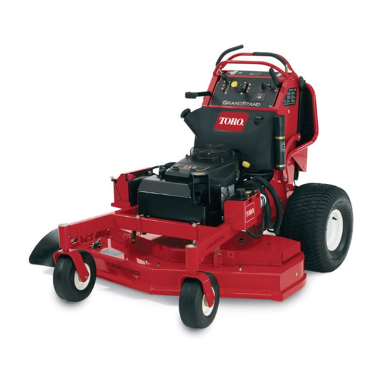
Toro GrandStand 74568TE Operator's Manual
Mower with 122cm turbo force cutting unit
Hide thumbs
Also See for GrandStand 74568TE:
- Operator's manual (68 pages) ,
- Operator's manual (68 pages) ,
- Operator's manual (68 pages)
Table of Contents
Advertisement
Quick Links
Download this manual
See also:
Operator's Manual
Advertisement
Table of Contents

Related Manuals for Toro GrandStand 74568TE


Summary of Contents for Toro GrandStand 74568TE
-
Page 1: Cutting Unit
Form No. 3365-228 Rev A GrandStand ® Mower With 122cm TURBO FORCE ® Cutting Unit Model No. 74568TE—Serial No. 310000001 and Up g012175 To register your product or download an Operator's Manual or Parts Catalog at no charge, go to www.Toro.com. Original Instructions (EN) -
Page 2: Table Of Contents
Authorized Service Vibration Level............. 6 Slope Indicator............. 7 Dealer or Toro Customer Service and have the model and serial numbers of your product ready. Figure 1 Safety and Instructional Decals ......8 identifies the location of the model and serial numbers Product Overview ............ - Page 3 Adjusting the Anti-Scalp Rollers (60 inch Schematics ..............61 Mower Decks Only) ........24 Adjusting the Flow Baffle ........25 Positioning the Flow Baffle......... 25 Using the Mid-Size Weight........26 Maintenance............... 27 Recommended Maintenance Schedule(s) ....27 Premaintenance Procedures........28 Raising the Mower for Access ......
-
Page 4: Safety
To reduce the potential for injury, conditions, especially slopes comply with these safety instructions. – incorrect load distribution Toro designed and tested this mower for reasonably safe service; however, failure to comply with the following Gasoline instructions may result in personal injury. -
Page 5: Toro Mower Safety
– before clearing blockages or unclogging chute. The following list contains safety information specific – before checking, cleaning or working on the lawn to Toro products and other safety information you must mower. know. – after striking a foreign object, inspect the lawn... -
Page 6: Sound Pressure
• Check brake operation frequently. Adjust and service attempting to maintain, adjust or service. as required. • Use only Toro approved attachments. Warranty may be voided if used with unapproved attachments. Sound Pressure • Check carefully for overhead clearances (i.e. -
Page 7: Slope Indicator
Slope Indicator G011841 Figure 3 This page may be copied for personal use. 1. The maximum slope you can safely operate the machine on is 20 degrees. Use the slope chart to determine the degree of slope of hills before operating. Do not operate this machine on a slope greater than 20 degrees. Fold along the appropriate line to match the recommended slope. -
Page 8: Safety And Instructional Decals
Safety and Instructional Decals Safety decals and instructions are easily visible to the operator and are located near any area of potential danger. Replace any decal that is damaged or lost. 93-7010 110-2067 1. Thrown object hazard—keep bystanders a safe distance from the machine. - Page 9 115-4212 1. Hydraulic oil level 3. Warning—do not touch the hot surface. 2. Read the Operator’s Manual. 117-3628 1. Belt tension adjustment: 5.75 inches (146 mm) 116–3267 >10∞ 116-3290 >20∞ 119–8663 1. Tipping hazard—do not mow up or down slopes greater than 10 degrees;...
- Page 10 Battery Symbols Some or all of these symbols are on your battery 1. Explosion hazard 6. Keep bystanders a safe distance from the battery. 2. No fire, open flame, or 7. Wear eye protection; smoking. explosive gases can cause blindness and other injuries 3.
- Page 11 119-7245 1. Parking brake—disengage 4. Fast 7. Power Take-off (PTO)—engage 2. Parking brake—engage 5. Continuous variable setting 8. Power Take-off (PTO)—disengage 3. Traction control 6. Slow 9. Engine speed 119-7285 1. Read the Operator’s Manual before 3. Lubricate every 50 hours 5.
-
Page 12: Product Overview
Product Overview g012844 Figure 5 1. Parking brake lever 8. Fuel cap Figure 4 2. Choke 9. Height-of-cut pin 1. Side discharge chute 7. Control levers 3. Hour meter 10. Platform latch 2. Battery 8. Manual tube 4. Ignition switch 11. -
Page 13: Specifications
Contact your Authorized Service Dealer or Distributor or go to www.Toro.com for a list of all approved attachments and accessories. Specifications Note: Specifications and design are subject to change without notice. Figure 6 122cm mowers: 1. -
Page 14: Operation
Operation DANGER In certain conditions during fueling, static Note: Determine the left and right sides of the electricity can be released causing a spark which machine from the normal operating position. can ignite the gasoline vapors. A fire or explosion from gasoline can burn you and others and can damage property. -
Page 15: Checking The Engine Oil Level
Breaking In a New Machine Note: A fuel stabilizer/conditioner is most effective when mixed with fresh gasoline. To New engines take time to develop full power. Mower minimize the chance of varnish deposits in the fuel decks and drive systems have higher friction when new, system, use fuel stabilizer at all times. -
Page 16: Operating The Mower Blade Control Switch (Pto)
G009174 Figure 10 Figure 8 1. Parking brake engaged 2. Parking brake released Operating the Throttle Releasing the Parking Brake The throttle control can be moved between Fast and Slow positions (Figure 11). Pull the brake lever back and over into the slot and push the parking brake lever forward. -
Page 17: Operating The Ignition Switch
Using the Speed Control Lever This machine has a speed control lever that sets the maximum ground speed of the machine. This can be adjusted to the operator’s desired speed. It is recommended to use the slowest speed for new operator’s. -
Page 18: Starting And Stopping The Engine
Figure 16 7. Turn the ignition key to the Start position G008948 (Figure 13). When the engines starts, release the key. Figure 15 Important: Do not engage starter for more 1. On 2. Off than 5 seconds at a time. If the engine fails to start allow a 15 second cool-down period between attempts. -
Page 19: The Safety Interlock System
Stopping the Engine The Safety Interlock System CAUTION CAUTION Children or bystanders may be injured if they If safety interlock switches are disconnected or move or attempt to operate the tractor while it is damaged the machine could operate unexpectedly unattended. -
Page 20: Operating The Platform
Operating the Machine with the 3. Move the right side motion control lever to the center, un-locked position. The blades should Platform Up not rotate. Operating the machine with the platform up is 4. Move the motion control levers forward. The recommended when: engine should kill. -
Page 21: Driving Forward Or Backward
G012182 Figure 21 1. Front reference bar 4. Right control lever 5. Right control lever in the 2. Left control lever neutral lock position 3. Rear reference bar 3. To go forward, move the speed control lever to the desired speed. Figure 20 4. -
Page 22: Stopping The Machine
Set the parking brake when you leave the machine; refer to Setting the Parking Brake in Operation. Remember to remove the key from the ignition switch. CAUTION Children or bystanders may be injured if they move or attempt to operate the tractor while it is unattended. -
Page 23: Transporting Machines
4. Push the machine to the desired location. extend beyond the rear tires is recommended instead of individual ramps for each side of the unit (Figure 26). 5. Set the parking brake. The platform when down and locked into position, 6. -
Page 24: Side Discharging Or Mulching The Grass
1. Move the height-of-cut lever to the transport position (all the way up). 2. Select a hole in the height-of-cut bracket corresponding to the height-of-cut desired and, insert the pin (Figure 27). 3. Lower the height-of-cut lever to the pin (Figure 27). Figure 26 1. -
Page 25: Adjusting The Flow Baffle
Figure 29 3. Rotate cam to increase or 1. Cam lock decrease locking pressure Figure 28 2. Lever 4. Slot 1. Bushing 4. Bolt 2. Anti-scalp roller 5. Nut 3. Spacer Positioning the Flow Baffle The following figures are only recommendations for Adjusting the Flow Baffle use. -
Page 26: Using The Mid-Size Weight
• Use in tall, dense grass mowing conditions. • Use in wet conditions. • Lowers the engine power consumption. • Allows increased ground speed in heavy conditions. • This position is similar to the benefits of the Toro SFS mower. -
Page 27: Maintenance
• Change the hydraulic filter and hydraulic oil when using Mobil® 1 oil. Every 250 hours • Adjust the caster pivot bearing. • Check the electric clutch. • Change the hydraulic filter and hydraulic oil when using Toro® HYPR-OIL™ 500 Every 500 hours hydraulic oil. • Change the hydraulic filter. -
Page 28: Premaintenance Procedures
Premaintenance Procedures Raising the Mower for Access The front of the mower can be raised and supported on its back for access under the machine for maintenance. 1. Raise the platform. Refer to Operating the Platform in Operation. 2. Remove the battery. Figure 34 3. -
Page 29: Release The Cushion For Rear Access
Figure 35 1. Remove battery 2. With two people, lift the front end of the mower Figure 36 (ensure the platform is up) 1. Plastic bushing with large 3. Hairpin cotter pin washer 2. Cushion bracket with key Release the Cushion for Rear hole Access The cushion can be released for rear access to the... -
Page 30: Lubrication
Lubrication Grease with No. 2 general purpose lithium base or molybdenum base grease. Lubricate the traction rollers with a dry lubricant (PTFE). How to Grease 1. Disengage the PTO and set the parking brake. 2. Stop the engine, remove the key, and wait for all moving parts to stop before leaving the operating position. -
Page 31: Greasing The Front Caster Pivots
Greasing the Front Caster 8. If the axle assembly has had both spacer nuts removed (or broken loose), apply a thread locking Pivots adhesive to one spacer nut and thread onto the axle with the wrench flats facing outward. Do Not thread Service Interval: Yearly spacer nut all of the way onto the end of the axle. -
Page 32: Engine Maintenance
Engine Maintenance Servicing the Air Cleaner Service Interval/Specification Inspect the foam and paper elements and replace them if they are damaged or excessively dirty. Note: Service the air cleaner more frequently (every few operating hours) if the operating conditions are extremely dusty or sandy. -
Page 33: Servicing The Engine Oil
2. Place the air cleaner assembly onto the air cleaner base or hose and secure it (Figure 42). 3. Place the air cleaner cover into position and tighten the cover knob (Figure 42). Servicing the Engine Oil Service Interval: Before each use or daily—Check the engine oil level. -
Page 34: Changing The Engine Oil
Checking the Engine Oil Level Note: Check the oil when the engine is cold. WARNING Contact with hot surfaces may cause personal injury. Keep hands, feet, face, clothing and other body parts away the muffler and other hot surfaces. Important: Do not overfill the crankcase with oil because damage to the engine may result. -
Page 35: Changing The Engine Oil Filter
3. Disengage the PTO, move the motion control levers to the neutral locked position and set the parking brake. 4. Stop the engine, remove the key, and wait for all moving parts to stop before leaving the operating position (Figure 46). G008796 Figure 47 Changing the Engine Oil Filter... -
Page 36: Servicing The Spark Plug
Removing the Spark Plug 1. Disengage the PTO, move the motion control levers to the neutral locked position and set the parking brake. 2. Stop the engine, remove the key, and wait for all moving parts to stop before leaving the operating position. -
Page 37: Fuel System Maintenance
Fuel System Maintenance Draining the Fuel Tank Note: There is no other recommended way to drain fuel from the tank, other than using a syphon pump. A Figure 51 syphon pump can be purchased at a hardware store. DANGER In certain conditions, gasoline is extremely flammable and highly explosive. -
Page 38: Servicing The Fuel Filter
Servicing the Fuel Filter Electrical System Maintenance Replacing the Fuel Filter Service Interval: Yearly Servicing the Battery Never install a dirty filter if it is removed from the fuel Service Interval: Every 100 hours line. Always keep the battery clean and fully charged. Use Note: Note how the fuel filter is installed in order to a paper towel to clean the battery case. -
Page 39: Charging The Battery
WARNING Incorrect battery cable routing could damage the machine and cables causing sparks. Sparks can cause the battery gasses to explode, resulting in personal injury. • Always Disconnect the negative (black) battery cable before disconnecting the positive (red) cable. • Always Reconnect the positive (red) battery cable before reconnecting the negative (black) cable. -
Page 40: Servicing The Fuses
Drive System Maintenance Adjusting the Tracking Note: Determine the left and right sides of the machine from the normal operating position. 1. Push both control levers forward the same distance. Figure 55 2. Check if the machine pulls to one side. If it does, stop the machine and set the parking brake. -
Page 41: Checking The Tire Pressure
Checking the Tire Pressure Service Interval: Every 50 hours/Monthly (whichever comes first) Maintain the air pressure in the rear tires at 12-14 psi (83-97 kPa). Uneven tire pressure can cause an uneven cut. Note: The front tires are semi-pneumatic tires and do not require air pressure maintenance. -
Page 42: Adjusting The Electric Clutch
2. Remove one bushing, then pull the spanner bushing and roller bearing out of the wheel hub (Figure 60). 3. Remove the other bushing from the wheel hub and clean any grease and dirt from the wheel hub (Figure 60). 4. -
Page 43: Cooling System Maintenance
Cooling System Maintenance Cleaning the Air Intake Screen Service Interval: Before each use or daily Before each use remove any build-up of grass, dirt or other debris from the cylinder and cylinder head cooling fins, air intake screen on flywheel end, and carburetor-governor levers and linkage. -
Page 44: Brake Maintenance
Brake Maintenance Servicing the Brake Before each use, check brakes on both a level surface and slope. Always set the parking brake when you stop the machine or leave it unattended. If the parking brake does not hold securely, an adjustment is required. Checking the Parking Brake Service Interval: Before each use or daily 1. - Page 45 6. Loosen the jam nut (Figure 64). 7. Rotate the yoke. To tighten the brake, rotate the yoke up. To loosen the brake, rotate the yoke down (Figure 64). 8. Secure the yoke to lower brake lever with the hair pin cotter pin and clevis pin (Figure 64).
-
Page 46: Belt Maintenance
Belt Maintenance Replacing the Mower Deck Belt Service Interval: Every 100 hours—Check the mower deck belt. Squealing when the belt is rotating, blades slipping when cutting grass, frayed belt edges, burn marks and cracks are signs of a worn deck belt. Replace the deck belt if any of these conditions are evident. -
Page 47: Controls System Maintenance
Controls System Maintenance Adjusting the Motion Control Handle Positions Adjusting the Right Side Motion Control Lever If the motion control levers do not align horizontally, adjust the right side motion control lever. Note: Adjust the horizontal alignment before the front to back alignment. -
Page 48: Motion Control Levers
Figure 69 1. Switch screws 3. Nut and bolt 2. Cam Figure 70 9. After the cam is adjusted, the lever switch needs to 1. Switch 3. Right motion control lever be checked. in the neutral unlocked position 10. Check the gap between the control lever and switch 2. -
Page 49: Hydraulic System Maintenance
Hydraulic System Maintenance Servicing the Hydraulic System Hydraulic Oil Type: Toro ® HYPR-OIL ™ ® hydraulic oil or Mobil 1 15W-50 synthetic motor oil. Hydraulic System Oil Capacity: 67 oz. (2.0 l) Figure 71 Important: Use oil specified. Other fluids could cause system damage. - Page 50 1 oil. refer to Bleeding Hydraulic System. Every 500 hours—Change the 12. Check the level of the fluid and add fluid, if required. hydraulic filter and hydraulic oil Do not overfill. when using Toro ® HYPR-OIL ™ hydraulic oil. WARNING Hot hydraulic fluid can cause severe burns.
-
Page 51: Bleeding The Hydraulic System
Replacing the Hydraulic Filter Service Interval: After the first 8 hours Every 500 hours/Yearly (whichever comes first) WARNING Hot hydraulic fluid can cause severe burns. Allow the hydraulic fluid to cool before performing any maintenance to the hydraulic system. Figure 76 1. -
Page 52: Mower Deck Maintenance
Mower Deck Check hydraulic hoses and hoses for leaks, loose fittings, kinked hoses, loose mounting supports, wear, weather Maintenance and chemical deterioration. Make necessary repairs before operating. Note: Keep areas around hydraulic system clean from Servicing the Cutting Blades grass and debris build up. To ensure a superior quality of cut, keep the blades sharp. -
Page 53: Removing The Blades
Checking for Bent Blades performance and continued safety conformance of the machine, use genuine Toro replacement blades. 1. Disengage the PTO, move the motion control levers Replacement blades made by other manufacturers may to the neutral locked position and set the parking result in non-conformance with safety standards. -
Page 54: Correcting The Mower Quality Of Cut
position. Disconnect the spark plug wire(s) from the spark plug(s). 3. Adjust the tire pressure in the rear tires to 12-14 psi (83-97 kPa). Figure 81 4. Check that the blades and spindle shafts are not 1. Blade 2. Balancer bent. - Page 55 1. Change the rear tire pressure. Do this to the corresponding side that needs adjustment. 2. Locate the U-plates on the side of the engine deck (Figure 84). 3. Loosen the U-plate on one side and adjust it up or down to make the difference between measurements B and C no more than a 1/4 inch (6 mm) (Figure 84).
-
Page 56: Replacing The Grass Deflector
5. Check the front-to-rear pitch of the cutting unit. 6. If the dimensions are not correct, adjust the front and rear nuts on either side to get the correct front-to-rear pitch (Figure 87). Figure 88 1. Measure from a level 2. -
Page 57: Cleaning
Cleaning 1. Remove the locknut, bolt, spring and spacer holding the deflector to the pivot brackets (Figure 90). Remove damaged or worn grass deflector. Cleaning Under the Mower Service Interval: Before each use or daily Remove the grass buildup under the mower daily. 1. -
Page 58: Storage
Storage and distribute the oil inside the cylinder. Install the spark plug(s). Do not install the wire on the spark plug(s). Cleaning and Storage 10. Check and tighten all bolts, nuts, and screws. Repair 1. Disengage the power take off (PTO), set the parking or replace any part that is damaged or defective. -
Page 59: Troubleshooting
Troubleshooting Problem Possible Cause Corrective Action Engine will not start, starts hard, or fails 1. Fuel tank is empty. 1. Fill fuel tank with gasoline. to keep running. 2. Choke is not on. 2. Move the choke lever to choke position. 3. - Page 60 Problem Possible Cause Corrective Action Blades do not rotate. 1. Pump drive belt is worn, loose or 1. Check the belt tension. broken. 2. Install drive belt and check adjusting 2. Pump drive belt is off pulley. shafts and belt guides for correct position.
- Page 61 Schematics Hydraulic Schematic (Rev. A)
- Page 62 Electrical Schematic (Rev. A)
- Page 63 Spypros Stavrinides Limited Cyprus 357 22 434131 Surge Systems India Limited India 91 1 292299901 T-Markt Logistics Ltd. Hungary 36 26 525 500 Toro Australia Australia 61 3 9580 7355 Toro Europe BVBA Belgium 32 14 562 960 374-0269 Rev A...
- Page 64 Repairs necessary due to improper fuel, contaminants in the fuel *Whichever occurs first. system, or failure to properly prepare the fuel system prior to any **Some engines used on Toro LCE Products are warranted by the engine manufacturer. period of non-use over three months. •...