Advertisement
Quick Links
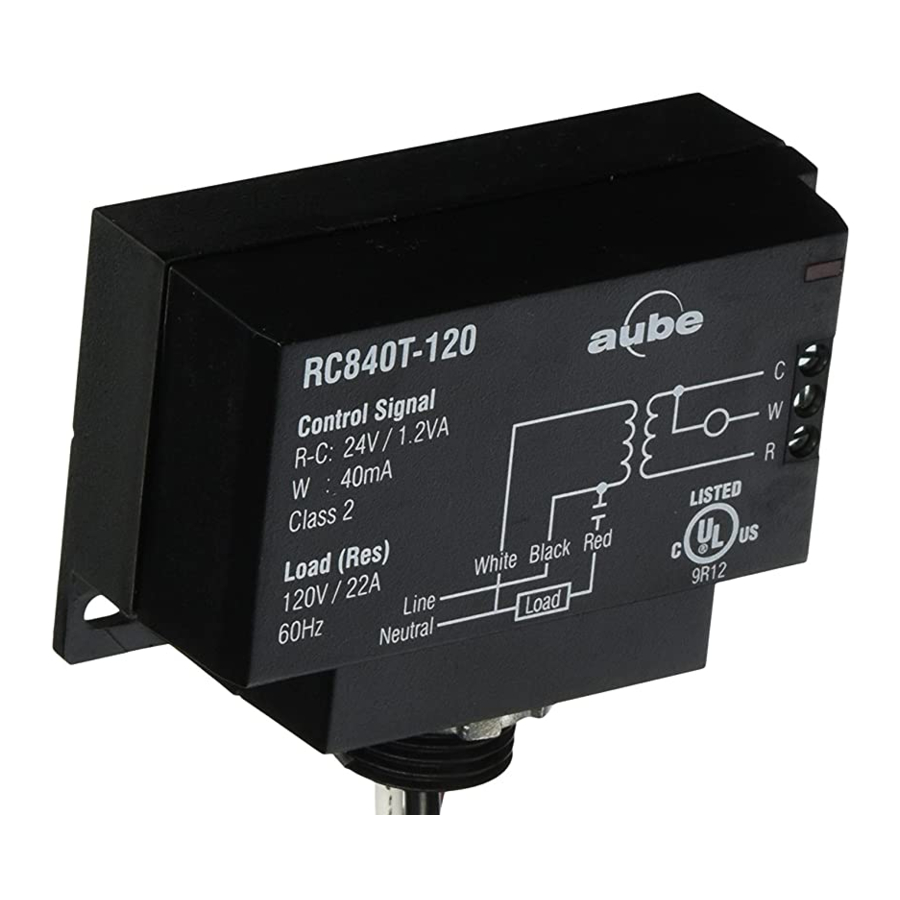
Application
The RC840T Electric Heating Relay is designed to control a line
voltage resistive load from a low voltage thermostat. The RC840T
relay has a built-in 24 V transformer and is compatible with 3-wire
(R,C,W) thermostats as well as 2-wire mechanical and battery-
operated thermostats.
The RC840T operates silently and can be installed in bedrooms,
living rooms, or any other occupied area without disturbing
occupants. On a call for heat, the relay is immediately activated;
there is no delay. This increases temperature control and comfort.
NOTE:
Not recommended for fast-cycling modulated regulation. For
fast-cycling heating equipment, It is recommended to use the RT850
or RT850T (integrated 24 V transformer) Solid State Relay.
I
Installation
The RC840T must be installed in an area where the temperature is
between -4°F and 140°F (-20°C and 60°C).
The RC840T can be installed on the side of an electrical box or a
distribution panel or inside the wiring compartment of an electric
baseboard.
On the side of
an electrical box
All wiring must comply with national and local electrical
code regulations.
Installation should be carried out by an electrician.
Disconnect power supply before installing the relay to
prevent electrical shock.
Secure relay to the mounting surface using the two mounting
brackets. Use the supplied lock nut to secure the relay to the
junction box.
Wire the relay and connect according to typical wiring diagrams
(refer to figures 1 & 2).
RC840T
On/Off Switching Electric Heating Relay with Built-in 24 V Transformer
For proper installation, use
a screw and a washer.
Inside the wiring compartment
of a baseboard
1.
Once mounting and wiring have been completed, return power
to the heating system and test the installation.
Increase the thermostat temperature to activate the relay. Allow
system operation long enough to proof installation. Once
installation has been proofed, set temperature to normal
setpoint.
Typical Wiring Diagrams
2.
Low-voltage
2-wire
thermostat
You must provide an overload protection and
disconnect as required.
Figure 1 :
Connection to a 2-wire low voltage thermostat
Low-voltage
3-wire
thermostat
You must provide an overload protection and
disconnect as required.
Figure 2 :
Connection to a 3-wire low voltage thermostat
RC840T
Installation Guide
Load
Junction box
Red
Black
Blue
Load
Junction box
Red
Black
Blue
400-276-002-C
17/1/07
3.
1/2
Advertisement

Related Manuals for Aube Technologies RC840T


Summary of Contents for Aube Technologies RC840T
-
Page 1: Installation Guide
The RC840T must be installed in an area where the temperature is between -4°F and 140°F (-20°C and 60°C). The RC840T can be installed on the side of an electrical box or a distribution panel or inside the wiring compartment of an electric baseboard. -
Page 2: Electrical Specifications
0 to 95% non-condensing weight: 11.5 oz. (326 g) Terminal wire size: 12 AWG Certification: RC840T Dimensions Dimensions are expressed in INCHES [MM] RC840T Warranty AUBE warrants this product, excluding battery, to be free from defects in the workmanship or materials, under normal use and ser- vice, for a period of three (3) years from the date of purchase by the consumer.