Table of Contents
Advertisement
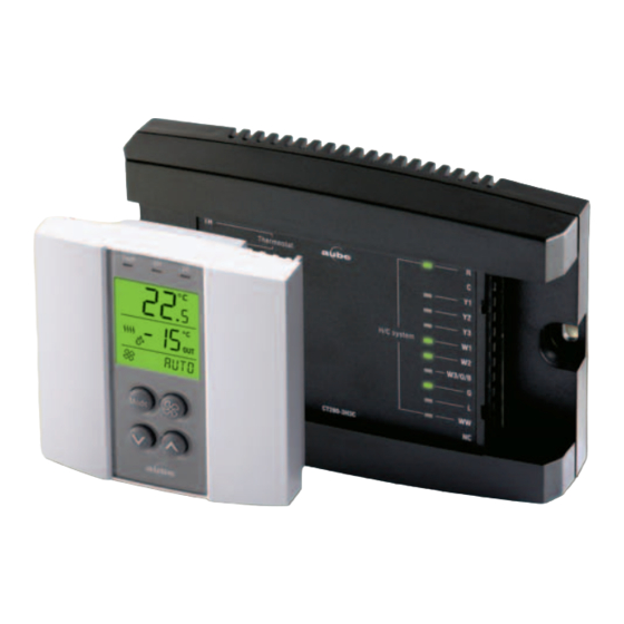
TH146 User Console
* To remove a connector from the control module, pry with a screwdriver.
1. Introduction
1.1
Applications
The TH146-N-U electronic controller can be used with any of the fol-
lowing heating/cooling systems:
Heat pump
1H1C, 2H1C, 2H2C, 3H1C, 3H2C, 3H3C, 4H2C
1H, 2H, 3H, 1C, 2C, 3C, 1H1C, 1H2C, 2H1C, 2H2C,
HVAC
2H3C, 3H1C, 3H2C, 3H3C
The following devices can be connected to the controller:
air recirculation fan
humidifier
dehumidifier or air exchanger
dual-register meter (dual energy)
remote control device (for the unoccupied mode)
1.2
Supplied Parts
• CT280-3H3C control module
• TH146 console with two wall anchors and mounting screws
• AC144-03 outdoor temperature sensor (3 m or 10 ft) with mount-
ing clip (see section 2.7)
1.3
Accessories
• RC845 relay (see section 2.4)
• AC146-410 plenum temperature sensor (see section 2.8)
• CT241 telephone controller (see section 2.10)
TH146-N-U
Removable
Connector *
CT280-3H3C Control Module
Non-programmable H/C Controller
Removable
Connector *
2. Installation
2.1
Control Module (CT280-3H3C)
Configure the control module according to your type of heating/cool-
ing system using DIP switches on the back of the module.
Heat pump
Install the control module near the heating/cooling system, away
from any heat source.
2.2
User Console (TH146)
Install the console in a central location. Avoid locations with air
drafts (e.g., top of staircase or air outlet) or stagnant air (behind a
door). Do not install the console on a wall hiding air ducts nor
expose it to direct sunlight.
NOTE: If this controller replaces an old thermostat, any two of the
wires that were connected to the thermostat can be used to connect
the user console to the control module. The maximum wiring length
is 30 m (100 ft).
TH146-N-U
Installation Guide
AC144-03 Outdoor
Temperature Sensor
HVAC
1/12
Advertisement
Table of Contents

Related Manuals for Aube Technologies TH146-N-U

Summary of Contents for Aube Technologies TH146-N-U
-
Page 1: Installation Guide
TH146-N-U Installation Guide Non-programmable H/C Controller Removable Removable Connector * Connector * AC144-03 Outdoor Temperature Sensor TH146 User Console CT280-3H3C Control Module * To remove a connector from the control module, pry with a screwdriver. 1. Introduction 2. Installation Applications Control Module (CT280-3H3C) The TH146-N-U electronic controller can be used with any of the fol- Configure the control module according to your type of heating/cool-... - Page 2 Install the sensor on the side of the plenum and Choose a location about 1.5 m (5 ft) above the floor on an position it such that its aperture faces the air flow. inside wall. Loosen the captive screw under the console. Connect the sensor to controller terminals PS and CS (no polarity).
-
Page 3: Principles Of Operation
the controller is configured for a new installation, the heat pump 4. Principles of Operation and the auxiliary heat can operate simultaneously. Interstage Delay Automatic Heating/Cooling Changeover Interstage Delay is the time allocated for the temperature to return to an acceptable value when it deviates too far from the setpoint. If With automatic heating/cooling mode changeover, there’s no need this time has elapsed, the next heating or cooling stage is activated. - Page 4 Wiring Tables Heat Pump Terminal Device 1H1C 2H1C 3H1C 2H2C 3H2C 4H2C 3H3C Console Connect the console between the TH terminals (no polarity) Plenum sensor Connect the plenum sensor between the PS and CS terminals (no polarity) Common S Common terminal for the plenum sensor and the outdoor sensor Outdoor sensor Connect the outdoor sensor between the CS and OS terminals (no polarity) Dual Energy...
- Page 5 Wiring Diagram: 2H1C Heat Pump — New Installation Compressor AC146-410 Auxiliary Heat AC144-03 Dual Energy Reversing Valve CT241 Humidifier Fault Dehumidifier Defrost TH146-N-U 5/12...
- Page 6 Wiring Diagram: 3H2C Heat Pump — Add-on Installation Compressor 1 AC146-410 Compressor 2 AC144-03 Dual Energy Reversing Valve CT241 Fault Humidifier Defrost Dehumidifier Furnace TH146-N-U 6/12...
- Page 7 Wiring Diagram: 3H2C HVAC Cooling Unit 1 AC146-410 Cooling Unit 2 AC144-03 Heating Unit 1 CT241 Heating Unit 2 Humidifier Heating Unit 3 Dehumidifier TH146-N-U 7/12...
-
Page 8: Configuration Menu
Configuration Menu Item HVAC Parameters Display Options Default Description Temperature format °C / °F °C Select the temperature display format. Set the bP L limit (see section 4.2). -30 to 10°C -10°C Balance point low NOTE: Lower bP L below its minimum (- -) if you do not wish to use this (-22 to 50°F) (14°F) function. -
Page 9: Operation
TH146-N-U User’s Guide Non-programmable H/C Controller Emergency heat Appears when the System fault indicator Dual energy temperature setpoint indicator is displayed Auxiliary heat is On Indoor temperature Heating is On Cooling is On System operating Outdoor temperature Fan operating mode selection or indoor humidity mode selection Fan is in... -
Page 10: Technical Specifications
TH146 USER CONSOLE Manual Setting In manual setting, the user sets the humidity level (5 to 60%). Temperature setpoint range: 5°C to 30°C (40°F to 86°F) Press the Mode button for 3 seconds. Humidity setpoint range: 5 to 60% Press the buttons to set the humidity Indoor temperature display range: 0°C to 70°C (32°F to 158°F) level. - Page 11 TH146-N-U 11/12...
- Page 12 Printed in USA 09/2011 TH146-N-U 12/12...