
Related Manuals for Toro 04351 Greensmaster 3050


Summary of Contents for Toro 04351 Greensmaster 3050
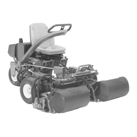
- Page 1 Form No. 3354–728 Rev C Greensmaster 3050 Greensmaster Traction Unit Model No. 04351—Serial No. 260000001 and Up Operator’s Manual Original Instructions (EN,GB)
-
Page 2: Table Of Contents
..... . . Evaporative Emission Control Warranty Statement ..The Toro General Commercial Products Warranty . . . Installing the Cutting Units . -
Page 3: Introduction
This machine meets or exceeds CEN standard EN additional information, contact an Authorized Service 836:1997, ISO standard 5395:1990, and ANSI Dealer or Toro Customer Service and have the model and B71.4-1999 specifications in effect at the time of serial numbers of your product ready. Figure 1 illustrates production when 40 lb. - Page 4 Operation – control of a ride-on machine sliding on a slope will not be regained by the application of the brake. The • Do not operate the engine in a confined space where main reasons for loss of control are: dangerous carbon monoxide fumes can collect.
-
Page 5: Toro Riding Mower Safety
Maintenance and Storage The following list contains safety information specific to Toro products or other safety information that you must • Keep all nuts, bolts and screws tight to be sure the know that is not included in the CEN, ISO, or ANSI equipment is in safe working condition. -
Page 6: Sound Pressure
Keep everyone away. – Reduce speed when making sharp turns. Avoid • To ensure safety and accuracy, have an Authorized Toro sudden stops and starts. Distributor check the maximum engine speed with a tachometer. Maximum governed engine speed should be –... -
Page 7: Safety And Instruction Decals
Safety and Instruction Decals Safety decals and instructions are easily visible to the operator and are located near any area of potential danger. Replace any decal that is damaged or lost. 106-9071 62–5070 93-8062 1. To lock the parking brake, 2. - Page 8 107-2554 1. Read the Operator’s Manual. 4. On 7. Fast 9. Headlights 2. Off 5. Slow 8. Failure/malfunction (Leak 10. Engine—stop detector alarm test) 3. Choke 6. Continuous variable setting 11. Engine—start 93-8063 (for CE) 104-2053 1. Warning—read the Operator’s Manual. 2.
- Page 9 93-8075 1. Press the lift pedal to 2. Press the mow pedal to raise and stop the reels. lower and start the reels. Battery Symbols Some or all of these symbols are on your battery. 1. Explosion hazard 7. Wear eye protection; explosive gases can 2.
-
Page 10: Specifications
Specifications Accessories Note: Specifications and design subject to change without notice. General Specifications 8 Blade DPA Cutting Unit Model No. 04610 11 Blade DPA Cutting Unit Model No. 04611 Width of Cut 59 in. (149.9 cm) Spiker Model No. 04494 Wheel Tread 49-1/2 in. -
Page 11: Setup
Setup Note: Determine the left and right sides of the machine from the normal operating position. Loose Parts Description Qty. Seat Mounting the seat slide and seat cover to the Nut, 5/16 in. seat base Seat cover Wheel assembly Mounting the rear wheel Rear spindle spacer Capscrew, 1/2 x 3/4 in. -
Page 12: Activating And Charging The Battery
Activating and Charging the Warning Battery Charging the battery produces gasses that can Use only electrolyte (1.265 Specific Gravity) to fill battery explode. initially. Never smoke near the battery and keep sparks and 1. Remove the wing nuts, washers, and battery clamp and flames away from battery. -
Page 13: Installing The Rear Wheel Assembly
Installing the Rear Wheel Mounting the Seat Assembly Note: Mount the seat slides in the front set of mounting holes to gain an additional 3 in. (7.6 cm) in the forward 1. Remove the bolt and locknut from the wheel mount adjustment, or in the rear mounting holes for an additional holes in the rear castor fork (Fig. -
Page 14: Mounting The Cover
Installing the Battery 1. Mount the battery with the battery terminals toward the hydraulic tank on the machine. Warning Battery terminals or metal tools could short against metal tractor components causing sparks. Sparks can cause the battery gasses to explode, resulting in personal injury. -
Page 15: Installing The Cutting Units
Installing the Cutting Units 5. Mount the baskets on the pull frames, loosen the jam nuts on the pull arms, and adjust the ball sockets until there is 1/4 to 1/2 in. (6 to 13 mm) clearance between the lip of the basket and the reel blades or the front For Cutting Unit Models 04610 and 04611 shield. -
Page 16: Rear Ballast
Note: Retain the protective covers for the cutting units. Install them whenever the reel drive motors are removed to protect the cutting unit bearings from contamination. 9. Using a hand pump grease gun, fill the cavity at the end of the cutting unit with #2 general purpose grease. 10. -
Page 17: Before Operating
Before Operating Filling the Gas Tank Use unleaded regular gasoline suitable for automotive use Note: Determine the left and right sides of the machine (85 pump octane minimum). Leaded regular gasoline may from the normal operating position. be used if unleaded regular is not available. Important Never use methanol, gasoline containing Checking the Engine Oil... -
Page 18: Servicing The Hydraulic System
Figure 15 Mobil. Contact your Toro Distributor for details. The oil is 1. Fuel tank cap available in 5 gallon (19 l) containers from your Toro Distributor, order part no. -
Page 19: Tire Pressure
Important To prevent system contamination, clean the top of the hydraulic oil containers before puncturing them. Ensure that the pour spout and funnel are clean. Note: Make a close visual inspection of the hydraulic components. Inspect them for Ieaks, loose fasteners, missing parts, improperly routed lines, etc. -
Page 20: Operation
Operation Parking Brake Button Depressing the brake pedal to actuate the brake assembly, then depressing the small button indicated (Fig. 18) will Note: Determine the left and right sides of the machine keep the brakes actuated for parking. Disengage it by from the normal operating position. -
Page 21: Throttle Control
Throttle Control The throttle control (Fig. 20) gives the operator the ability to control the speed of the engine. Moving the throttle control toward the Fast position increases the engine RPM; moving the throttle control toward Slow will decrease the engine RPM. -
Page 22: Break-In Period
If oil leaks machine at mowing speed until the brakes are hot, as continue to appear, contact your local Toro indicated by their smell. An adjustment to the brakes may Distributor for assistance and, if necessary, be required after break-in;... -
Page 23: Checking The Interlock System
If the engine did not crank, proceed to step 6. If the The purpose of the interlock system (Fig. 24) is to prevent engine cranked, contact your local Toro Distributor for the engine from cranking or starting unless the traction shift assistance. -
Page 24: Preparing The Machine For Mowing
Preparing the Machine for Before Mowing Mowing Inspect the green for debris, remove the flag from the cup, and determine the best direction to mow. Base the direction To assist in aligning the machine for successive cutting to mow on the previous mowing direction. Always mow in passes, it is suggested the following be done to the No. -
Page 25: Transport Operation
Transport Operation Make sure that the cutting units are in the full up position. Set the shift selector in No. 2 if conditions will permit faster ground speed. Shift to No. 1 and operate at slower ground speeds in rough or hilly areas. Use the brakes to slow the machine while going down steep hills to avoid loss of control. -
Page 26: Maintenance
Maintenance Note: Determine the left and right sides of the machine from the normal operating position. Recommended Maintenance Schedule Maintenance Service Maintenance Procedure Interval • Change the engine oil. After First 8 Hours • Replace the engine oil filter. • Check the battery fluid level. •... -
Page 27: Daily Maintenance Checklist
Daily Maintenance Checklist Duplicate this page for routine use. For the week of: Mon. Tues. Wed. Thurs. Fri. Sat. Sun. Maintenance Check Item Check the safety interlock operation. Check the instrument operation. Check the brake operation. Check the fuel level. Check the engine oil level. -
Page 28: Lubrication
Caution If you leave the key in the ignition switch, someone could accidently start the engine and seriously injure you or other bystanders. Remove the key from the ignition and disconnect the wire from the spark plug before you do any maintenance. -
Page 29: Changing The Engine Oil And Filter
Changing the Engine Oil and Filter Change the oil and filter after the first 8 hours of operation. Thereafter, change the oil every 50 hours and the filter every 100 hours. Figure 31 1. Remove the drain plug (Fig. 34) and let oil flow into a drain pan. -
Page 30: Servicing The Air Cleaner
Servicing the Air Cleaner 5. Reinstall the foam element, paper element, and air cleaner cover. Service the air cleaner foam pre-cleaner after every 50 Important Do not operate the engine without the air operating hours and the air cleaner cartridge after every 100 cleaner element because extreme engine wear and damage operating hours. -
Page 31: Adjusting The Choke Control
Adjusting the Choke Control 3. Bend the governed idle spring anchor tang (Fig. 38) to attain an idle speed of 1625±50 rpm. Check the speed with a tachometer. 1. Loosen the cable clamp screw securing the cable to the engine (Fig. 37). 2. -
Page 32: Replacing The Fuel Filter
Normally, change the hydraulic oil and filter after every not used, tighten the plug firmly. 2000 operating hours. If the oil becomes contaminated, contact your local Toro distributor because the system must be flushed. Contaminated oil looks milky or black when 0.030 in. -
Page 33: Checking The Hydraulic Lines And Hoses
4. Fill the hydraulic tank with approximately 4.5 gallons 2. If the brakes do not lock equally, disconnect the brake of hydraulic oil; refer to Checking the Hydraulic rods by removing the cotter pin and clevis pin (Fig. 43). System, page 18. 5. -
Page 34: Adjusting The Lift And Mow Pedal Height
Figure 44 1. Mounting capscrews 2. Cam blocks Figure 46 1. Jam nut 3. Control rod Adjusting the Lift and Mow 2. Yoke 4. Adjustment lever Pedal Height To gain proper spool travel in the valve bank, adjust the lift Leveling the Lift and Mow and mow pedals to equal heights as follows: Pedals... -
Page 35: Adjusting The Traction Pedal
Adjusting the Traction Pedal Adjusting Cutting Unit Lift and Drop To check the forward and reverse operation of the traction pedal, proceed as follows: The cutting unit lift/drop circuit is equipped with a flow control valve. This valve is preset at the factory at approximately 3-1/2 turns open, but an adjustment may be Adjusting Forward required to compensate for differences in hydraulic oil... -
Page 36: Replacing The Seat Switch
Replacing the Seat Switch Replacing the Traction Switch 1. Pivot the seat forward and secure it with the support 1. Pivot the seat forward and secure it with the support rod. rod.. 2. Remove the boot from the button end of the seat switch 2. -
Page 37: Adjusting The Traction Return Linkage
Servicing the Steering 5. Connect a continuity tester or ohm meter across the switch terminals and turn the switch in until continuity Assembly occurs. Then rotate the switch in 1/2 turn (180 degrees) and secure the jam nut to 75 in.-lb. (8 N⋅m) against the The steering cable tension should be adjusted whenever bonnet. -
Page 38: Battery Care
Battery Care If corrosion occurs at the terminals, disconnect the cables, negative (–) cable first, and scrape the clamps and terminals separately. Reconnect the cables, positive (+) cable first, Warning and coat the terminals with petroleum jelly. Storage Battery posts, terminals, and related accessories contain lead and lead compounds, chemicals known to the State of California to cause cancer If you wish to store the machine for a long period of time,... -
Page 39: Schematics
Electrical Schematic... - Page 40 Hydraulic Schematic...
-
Page 41: Troubleshooting
Troubleshooting Problem Possible Causes Corrective Action 1. The fuel tank is empty. 1. Fill the fuel tank. Engine: The engine loses power. 2. A fuel line is clogged or there is 2. Clean the fuel tank. Use clean debris in the fuel tank. gasoline. - Page 42 Problem Possible Causes Corrective Action 3. The traction relief cartridge in the 3. Remove the relief cartridge. Repair In the hydraulic system there is no #1 #4 spool section is open. or replace it. or reverse traction speed. The #2 o e e se t act o speed speed is normal.
- Page 43 5. An improper suction line(s) is 5. Remove the suction line and installed. The line collapsed. replace with genuine Toro parts. 6. A line fitting has a blockage. 6. Repair as necessary. 7. A motor is excessively worn.
- Page 44 Problem Possible Causes Corrective Action 1. The mow/lift switch, traction switch, 1. Refer to Replacing the Traction The engine fails to crank, regardless of and/or seat switch are adjusted Switch, Replacing the Mow/Lift the shift selector or mow pedal incorrectly or are damaged. Switch, and/or Replacing the Seat position.
- Page 45 Problem Possible Causes Corrective Action 1. The seat switch is adjusted 1. Refer to Replacing the Seat The engine does not continue to run incorrectly or is damaged. Switch. when sitting on the seat and the shift e s tt g o t e seat a d t e s selector is placed in gear or the mow 2.
-
Page 47: Evaporative Emission Control Warranty Statement
Company. Owner’s Warranty Responsibilities: ® As the equipment owner, you are responsible for performance of the required maintenance listed in your Operator’s Manual. The Toro • ® Company recommends that you retain all receipts covering maintenance on your equipment, but The Toro Company cannot deny warranty solely for the lack of receipts. -
Page 48: The Toro General Commercial Products Warranty
If for any reason you are dissatisfied with your Distributor’s service or have difficulty obtaining guarantee information, contact the Toro importer. If all other remedies fail, you may contact us at Toro Warranty Company.