KTM 990 Supermoto T Owner's Manual
Hide thumbs
Also See for 990 Supermoto T:
- Owner's manual (218 pages) ,
- Owner's manual (219 pages) ,
- Owner's manual (201 pages)
Table of Contents
Advertisement
Quick Links
Advertisement
Table of Contents

Related Manuals for KTM 990 Supermoto T


Summary of Contents for KTM 990 Supermoto T
- Page 1 OWNER'S MANUAL 2010 990 Supermoto R USA 990 Supermoto T USA Art. no. 3211562en...
- Page 3 KTM accepts no liability for delivery options, deviations from illustrations and descriptions, as well as misprints and other errors.
- Page 4 Reproduction, even in part, as well as copying of all kinds, is permitted only with the express written permission of the copyright owner. ISO 9001(12 100 6061) According to the international quality management standard ISO 9001, KTM uses quality assurance processes that lead to the maximum possible quality of the products.
-
Page 5: Table Of Contents
TABLE OF CONTENTS Combination instrument - indicator lamps......42 TABLE OF CONTENTS MEANS OF REPRESENTATION ..........7 Combination instrument - display........43 IMPORTANT INFORMATION ........... 8 Combination instrument - speedometer....... 44 Overview of labels (Supermoto T) ........12 Setting kilometers or miles ..........44 Overview of labels (Supermoto R)........ - Page 6 TABLE OF CONTENTS RIDING INSTRUCTIONS ............61 Checking the chain tension ..........90 Checks before putting into operation ........61 Adjusting the chain tension ..........91 Starting ................62 Checking the chain, rear sprocket and engine sprocket..93 Starting up ..............63 Checking the front brake discs...........
- Page 7 TABLE OF CONTENTS Changing the headlight bulb..........125 Ignition curve plug-in connector........171 Changing the parking light bulb ........128 Adjusting the ignition curve to the fuel quality....171 Changing the turn signal bulb .......... 131 IMMOBILIZER BLINK CODE..........173 Changing the brake light bulb ..........
- Page 8 TABLE OF CONTENTS STANDARDS..............212 INDEX ................213...
-
Page 9: Means Of Representation
All work marked with this symbol requires specialist knowledge and technical understanding. In the interest of your own safety, have these jobs performed by an authorized KTM workshop! There, your motorcycle will be serviced opti- mally by specially trained experts using the specialist tools required. -
Page 10: Important Information
Warranty The work prescribed in the service schedule must be carried out by an authorized KTM workshop only and confirmed in the customer's ser- vice record; otherwise, all warranty claims will be void. No warranty claim can be honored for damage resulting from manipulation and/or other changes to the vehicle. - Page 11 Spare parts, accessories For your own safety, only use spare parts and accessory products that have been approved and/or recommended by KTM and have them installed by an authorized KTM workshop. KTM accepts no liability for other products and any resulting damage.
- Page 12 IMPORTANT INFORMATION – Switch off the engine and remove the ignition key. – Secure the motorcycle against falling over or rolling away using straps or other suitable devices. Environment Motorcycling is a wonderful sport and we naturally hope that you can enjoy it to the full. However, it can also lead to problems with the environment and conflict with other persons.
- Page 13 IMPORTANT INFORMATION...
-
Page 14: Overview Of Labels (Supermoto T)
IMPORTANT INFORMATION Overview of labels (Supermoto T) 601100-10... - Page 15 IMPORTANT INFORMATION Information on emission control Type label, Canada Information on operating substances and tires Information on noise emission Information on the fuel evaporation system Information on chain tension Information on suspension setting Type label, USA Information on preparing for use 601102-01 Information on emission control...
- Page 16 IMPORTANT INFORMATION 600962-01 Type label, Canada 600969-01 Information on operating substances and tires...
- Page 17 IMPORTANT INFORMATION 601103-01 Information on noise emission Information on the fuel evaporation system 600968-01...
- Page 18 IMPORTANT INFORMATION Information on chain tension 600966-01 Information on suspension setting 601104-01...
- Page 19 IMPORTANT INFORMATION 600963-01 Type label, USA Information on preparing for use 600961-01...
-
Page 20: Overview Of Labels (Supermoto R)
IMPORTANT INFORMATION Overview of labels (Supermoto R) 601101-10... - Page 21 IMPORTANT INFORMATION Information on emission control Type label, Canada Information on operating substances and tires Information on noise emission Information on preparing for use Information on the fuel evaporation system Information on chain tension Information on suspension setting Type label, USA 600964-01 Information on emission control...
- Page 22 IMPORTANT INFORMATION 600962-01 Type label, Canada 600969-01 Information on operating substances and tires...
- Page 23 IMPORTANT INFORMATION 600965-01 Information on noise emission Information on preparing for use 600961-01...
- Page 24 IMPORTANT INFORMATION Information on the fuel evaporation system 600968-01 Information on chain tension 600966-01 Information on suspension setting 600967-01...
- Page 25 IMPORTANT INFORMATION 600963-01 Type label, USA Notes/warnings Pay close attention to the notes/warnings. Info Various information and warning labels are affixed to the vehicle. Do not remove information/warning labels. If they are missing, you or others may not recognize potential hazards and may therefore be injured.
- Page 26 If NHTSA receives similar complaints, it may open an investigation. If it finds that a safety defect exists in a group of vehicles, it may order a recall and remedy campaign. However, NHTSA cannot become involved in individual problems between you, your dealer, or KTM...
- Page 27 Noise emission warranty KTM Sportmotorcycle AG warrants that this exhaust system, at the time of sale, meets all applicable U.S. EPA Federal noise standards. This warranty extends to the first person who buys this exhaust system for purposes other than resale, and to all subsequent buyers.
- Page 28 Consumer rights Warranty claims should be submitted to an authorized KTM workshop. If you are not satisfied, please contact: KTM North America, Inc., Customer Support, 1119 Milan Ave., Amherst, OH 44001, USA Phone: (440) 985–3553...
-
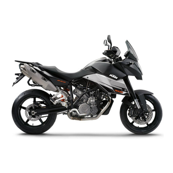
Page 30: View Of Vehicle
VIEW OF VEHICLE View of vehicle, front left side (vehicle differs slightly from photo) B00143-10... - Page 31 VIEW OF VEHICLE Combination instrument Filler cap Rear mirror Clutch lever Seat Handrails Shock absorber compression damping Shock absorber spring preload Engine number Shift lever Oil level viewer...
-
Page 32: View Of Vehicle, Rear Right Side (Vehicle Differs Slightly From Photo)
VIEW OF VEHICLE View of vehicle, rear right side (vehicle differs slightly from photo) B00142-10... - Page 33 VIEW OF VEHICLE Seat lock Light switch, headlight flasher switch, indicator switch, horn button Emergency OFF switch, electric starter button Hand brake lever Fork spring preload, fork rebound damping Chassis number Fork compression damping Type label Foot brake lever Passenger footrests Shock absorber rebound damping...
-
Page 34: Location Of Serial Numbers
LOCATION OF SERIAL NUMBERS Chassis number/type label The chassis number is stamped on the frame behind the steering head on the right. 601117-10 The type label for the USA is fitted on the frame tube on the right. 601116-10... -
Page 35: Key Number
LOCATION OF SERIAL NUMBERS The type label for Canada is fitted on the frame tube on the left. 601115-10 Key number The Code number key number can be found on the KEYCODECARD. Info You need the key number to order a spare key. Keep the KEYCODECARD in a safe place. -
Page 36: Engine Number
LOCATION OF SERIAL NUMBERS Engine number The engine number is stamped on the left side of the engine under the engine sprocket. B00120-10 Fork part number The fork part number is stamped on the inner side of the fork stub. ... -
Page 37: Shock Absorber Part Number
LOCATION OF SERIAL NUMBERS Shock absorber part number The shock absorber part number is stamped on the top of the shock absorber above the adjusting ring on the engine side. 700547-01... -
Page 38: Controls
CONTROLS Clutch lever The clutch lever is fitted on the left side of the handlebar. The clutch is hydraulically operated and self-adjusting. 700548-01 Hand brake lever The hand brake lever is fitted on the right side of the handlebar. ... -
Page 39: Light Switch
CONTROLS Light switch The light switch is fitted on the left side of the handlebar. Possible states Low beam on – The light switch is turned downwards. In this position, the low beam and tail light are switched on. High beam on –... -
Page 40: Turn Signal Switch
CONTROLS Turn signal switch The turn signal switch is fitted on the left side of the handlebar. Possible states Turn signal off Left turn signal on – The turn signal switch is pressed to the left. The turn signal switch automatically returns to the central position after use. Right turn signal on –... -
Page 41: Ignition/Steering Lock
CONTROLS Ignition/steering lock The ignition/steering lock is in front of the upper triple clamp. Info The ignition may only be switched on using a black ignition key. Use the orange programming key to activate and deactivate the black ignition key. Possible states Ignition OFF –... -
Page 42: Emergency Off Switch
The second black ignition key is activated when the vehicle is shipped. Two additional spare ignition keys (key number on the KEYCODECARD) can be ordered from an authorized KTM workshop, but they must be activated before use. Emergency OFF switch The emergency OFF switch is fitted on the right side of the handlebar. -
Page 43: Combination Instrument
CONTROLS Combination instrument 5.11 The combination instrument is installed in front of the handlebar. The combination instrument is divided into 4 function areas. Function buttons Tachometer Indicator lights Display 400920-10 Combination instrument - function buttons 5.12 You can change the display mode with the MODE button ... -
Page 44: Combination Instrument - Tachometer
CONTROLS Combination instrument - tachometer 5.13 The tachometer shows the engine speed in revolutions per minute. The red marking shows the excess speed range of the engine. 400922-10 Combination instrument - indicator lamps 5.14 The indicator lamps offer additional information about the operating state of the motorcy- cle. -
Page 45: Combination Instrument - Display
CONTROLS The oil indicator lamp lights up red – The oil pressure is too low. Warning lamp FI (MIL) lights up/flashes orange – The OBD has detected an emission- or safety-critical fault. The immobilizer indicator lamp lights up or flashes red – Status or error message for immobilizer/alarm system. -
Page 46: Combination Instrument - Speedometer
CONTROLS LEnGth Following the display function test, the LEnGth wheel circumference is shown for one sec- ond. Info 1870 mm corresponds to the circumference of the 17" front wheel with a series pro- duction tire. The display then changes to the last selected mode. 400837-01 Combination instrument - speedometer 5.16... -
Page 47: Combination Instrument - Time
CONTROLS Condition The motorcycle is stationary. – Switch on the ignition by turning the ignition key to the ON position. – Press the MODE button repeatedly until the ODO mode is active. – Keep the MODE button pressed until the display mode changes from km/h to mph or from mph to km/h. -
Page 48: Setting The Clock
CONTROLS Setting the clock 5.19 Condition The motorcycle is stationary. – Switch on the ignition by turning the ignition key to the ON position. – Press the MODE button repeatedly until the ODO mode is active. – Keep the MODE button and the SET button pressed simultaneously. The time display begins to flash. -
Page 49: Combination Instrument - Setting/Resetting Trip 1
CONTROLS Combination instrument - setting/resetting TRIP 1 5.21 Info The TRIP 1 trip counter is always running and counts up to 999.9. The trip counter can be used to measure the distance covered during trips or between two refueling stops. After the value 999.9 is reached, the trip counter starts at 0.0 again. -
Page 50: Combination Instrument - Trip F Display
CONTROLS – Switch on the ignition by turning the ignition key to the ON position. – Press the MODE button repeatedly until the TRIP 2 mode is active. – Keep the SET button pressed. The TRIP 2 display is set to 0.0. 400841-01 Combination instrument - TRIP F display 5.23... -
Page 51: Combination Instrument - Ambient Temperature Display
CONTROLS Combination instrument - ambient temperature display 5.24 The ambient temperature is displayed in °C or °F. 400893-13 Setting the temperature units 5.25 Condition The motorcycle is stationary. – Switch on the ignition by turning the ignition key to the ON position. -
Page 52: Combination Instrument - Warning Of Slippery Roads
CONTROLS Combination instrument - warning of slippery roads 5.26 The ice symbol lights up to indicate an increased danger of slippery roads. The ice symbol appears in the display when the ambient temperature drops below the specified value. Temperature 3 °C (37 °F) The ice symbol goes out in the display when the ambient temperature rises above the specified value again. -
Page 53: Opening The Filler Cap
CONTROLS Opening the filler cap 5.28 – Lift the cover of the filler cap and insert the ignition key. Note Danger of damage Ignition key breakage. – To take pressure off of the ignition key, push down on the filler cap. Damaged igni- tion keys must be replaced. -
Page 54: Handrails
CONTROLS Handrails 5.30 The handrails are used for moving the motorcycle around. If you carry a passenger, the passenger can hold onto the handrails during the trip. 600923-10 Seat lock 5.31 Seat lock is located at the rear under the tail light. ... -
Page 55: Tool Set
CONTROLS Tool set 5.32 The tool set is located in the storage compartment under the seat. 600924-10 Helmet lock 5.33 Warning Danger of accidents Impairment of ride behavior and vehicle operation if a helmet or helmet lock is attached to the vehicle. –... -
Page 56: Passenger Footrests
CONTROLS Passenger footrests 5.34 The passenger footrests can be folded up and down. Possible states Passenger footrests folded up – For operation without a passenger. • Passenger footrests folded down – For operation with a passenger. • B00127-01 Shift lever 5.35 Shift lever is mounted on the left side of the engine. -
Page 57: Foot Brake Lever
CONTROLS The gear positions can be seen in the photograph. The neutral or idle position is between the first and second gear. B00121-10 Foot brake lever 5.36 Foot brake lever is located in front of the right footrest. The rear brake is activated using the foot brake lever. -
Page 58: Side Stand
CONTROLS Side stand 5.37 Side stand is coupled with the safety start system; see the riding instructions. Possible states Side stand folded out – The vehicle can be leaned on the side stand. The safety start • system is active. Side stand folded in –... -
Page 59: Tips On Putting Into Operation
The front and rear wheels must be fitted with tires with similar tread patterns to prevent loss of control over the vehicle. Warning Danger of accidents Uncontrollable handling characteristic due to non-approved and/or non-recommended tires/wheels. – Only tires/wheels approved by KTM and with the corresponding speed index should be used. Warning Danger of accidents Reduced road grip with new tires. –... -
Page 60: Running In The Engine
TIPS ON PUTTING INTO OPERATION – Make sure that the pre-delivery inspection work has been carried out by an authorized KTM workshop. You receive a delivery certificate and the service record at vehicle handover. – Before your first trip, read the entire operating instructions carefully. - Page 61 TIPS ON PUTTING INTO OPERATION Warning Danger of accidents Unstable handling characteristics due to incorrect mounting of suitcase and/or tank rucksack. – Mount and secure suitcase and tank rucksack according to the manufacturer's instructions. Warning Danger of accidents Unstable handling characteristics at high speed. –...
- Page 62 TIPS ON PUTTING INTO OPERATION – If you are carrying baggage, make sure it is fixed firmly as close as possible to the center of the vehicle and ensure even weight distri- bution between the front and rear wheels. – Do not exceed the maximum permissible total weight and the axle loads.
-
Page 63: Riding Instructions
RIDING INSTRUCTIONS Checks before putting into operation Info Make sure that the motorcycle is in perfect technical condition before use. In the interests of riding safety, make a habit of making a general check before you ride. – Check the engine oil level. ( p. -
Page 64: Starting
RIDING INSTRUCTIONS Starting Danger Danger of poisoning Exhaust gases are poisonous and inhaling them may result in unconsciousness and/or death. – When running the engine, always make sure there is sufficient ventilation, and do not start or run the engine in an enclosed space without an effective exhaust extraction system. -
Page 65: Starting Up
RIDING INSTRUCTIONS – Press the emergency OFF switch into the position – Switch on the ignition by turning the ignition key to the ON position. After you switch on the ignition, you can hear the fuel pump working for about two seconds. -
Page 66: Shifting, Riding
RIDING INSTRUCTIONS Shifting, riding Warning Danger of accidents Abrupt load alterations can cause the vehicle to get out of control. – Avoid abrupt load alterations and sudden braking actions, and adapt your speed to the road conditions. Warning Danger of accidents If you change down at high engine speed, the rear wheel can lock up. –... - Page 67 RIDING INSTRUCTIONS Warning Danger of accidents Reduced road grip with cold tires. – On every journey, take the first miles carefully at moderate speed until the tires reach operating temperature and optimal road grip is ensured. Warning Danger of accidents Reduced road grip with new tires. –...
- Page 68 Info If you hear unusual noises while riding, stop immediately, switch off the engine and contact an authorized KTM workshop. – When conditions allow (incline, road situation, etc.), you can shift into a higher gear.
-
Page 69: Braking
Danger of accidents Reduced braking efficiency caused by spongy pressure point of front or rear brake. – Check the brake system and do not continue riding. (Your authorized KTM workshop will be glad to help.) Warning Danger of accidents Failure of brake system. -
Page 70: Stopping, Parking
RIDING INSTRUCTIONS Warning Danger of accidents Longer stopping distance due to higher overall weight. – Take the longer stopping distance into account when carrying a passenger and baggage. Warning Danger of accidents Delayed brake action on salted roads. – There may be salt deposits on the brake discs. In order to restore the normal braking efficiency, you will need to remove the deposits from the discs by carefully applying the brakes. - Page 71 RIDING INSTRUCTIONS – Always place the vehicle on a firm and even surface. Note Fire hazard Some vehicle components become very hot when the vehicle is operated. – Do not park the vehicle near flammable or explosive substances. Do not place objects on the vehicle while it is still warm from being run.
-
Page 72: Refueling
RIDING INSTRUCTIONS Refueling Danger Fire hazard Fuel is highly flammable. – Never refuel the vehicle near open flames or burning cigarettes, and always switch off the engine first. Be careful that no fuel is spilt, especially on hot vehicle components. Clean up spilt fuel immediately. –... - Page 73 RIDING INSTRUCTIONS – Switch off the engine. – Open the filler cap. ( p. 51) – Fill the fuel tank with fuel up to the lower edge of the fuel filler. Total fuel tank 19 l (5 US gal) Super unleaded (ROZ 95 / RON 95 / capacity, approx.
-
Page 74: Service Schedule
Check that the electrical equipment is functioning properly. • • • • • • • • Read out the trouble code memory using the KTM diagnostics tool. • • • • Change the engine oil and filter, clean the oil screens. p. 163) • •... - Page 75 Final inspection: Check the vehicle of roadworthiness and take a test ride. • • • • • • • • Read out the fault memory after a test ride using the KTM diagnostics tool. • • • • Make the service entries in the KTM DEALER.NET and service record.
- Page 76 SERVICE SCHEDULE K10N: Once after 1,000 km (621.4 mi) K75A: Every 7,500 km (4,660 mi) or annually K150A: Every 15,000 km (9,321 mi) or every 2 years K300A: Every 30,000 km (18,641 mi) or every 4 years...
-
Page 77: Maintenance Work On Frame And Engine
MAINTENANCE WORK ON FRAME AND ENGINE Jacking up motorcycle at the front Note Danger of damage The parked vehicle may roll away or fall over. – Always place the vehicle on a firm and even surface. – Jack up the motorcycle at the rear. ( p. -
Page 78: Jacking Up Motorcycle At The Rear
MAINTENANCE WORK ON FRAME AND ENGINE Jacking up motorcycle at the rear Note Danger of damage The parked vehicle may roll away or fall over. – Always place the vehicle on a firm and even surface. – Insert the work stand adapter in the rear of the work stand. Work stand adapter (61029055120) Work stand rear (61029055100) –... -
Page 79: Fork/Shock Absorber
MAINTENANCE WORK ON FRAME AND ENGINE Fork/shock absorber The fork and the shock absorber offer many options of adapting the suspension to your rid- ing style and the payload. Info To help you adapt the vehicle, we have summarized our findings in Table . - Page 80 MAINTENANCE WORK ON FRAME AND ENGINE – Turn adjusting screws clockwise until they stop. Info The adjusting screws are located at the bottom end of the fork legs. Make the same adjustment on both fork legs. – Turn back counterclockwise by the number of clicks corresponding to the fork type. Guideline (Supermoto R) Compression damping...
-
Page 81: Adjusting The Rebound Damping Of The Fork
MAINTENANCE WORK ON FRAME AND ENGINE Adjusting the rebound damping of the fork Info The hydraulic rebound damping determines the fork rebound behavior. An optimally adjusted rebound damping brakes the springing energy and enables a fast, vibration-free resetting of the fork to the zero position. -
Page 82: Adjusting The Spring Preload Of The Fork
MAINTENANCE WORK ON FRAME AND ENGINE Info Turn clockwise to increase suspension damping; turn counterclockwise to reduce damping. Adjusting the spring preload of the fork Info The spring preload defines the initial situation of the spring process of the fork. The spring preload setting is optimal when it is set for the weight of the rider and that of any baggage and a passenger, and thus ensures a compromise between maneuverability and stability. -
Page 83: Bleeding The Fork Legs
MAINTENANCE WORK ON FRAME AND ENGINE (Supermoto T) Spring preload - Preload Adjuster Comfort 5 turns Standard 5 turns Sport 3 turns Full payload 3 turns Info Turn clockwise to increase preload, turn counterclockwise to reduce spring preload. Changing the spring preload has no influence on the rebound damping although the adjusting screws turn during the adjustment work. -
Page 84: Compression Damping Of The Shock Absorber
Danger Danger of accidents Disassembly of pressurized parts can lead to injury. – The shock absorber is filled with high density nitrogen. Adhere to the description provided. (Your authorized KTM workshop will be glad to help.) Info The low-speed setting can be seen during the slow to normal compression of the shock absorber. - Page 85 MAINTENANCE WORK ON FRAME AND ENGINE – Turn adjusting screw clockwise with a screwdriver as far as the last perceptible click. Info Do not loosen nut – Turn back counterclockwise by the number of clicks corresponding to the shock absorber type.
-
Page 86: Adjusting The High-Speed Compression Damping Of The Shock Absorber
Danger Danger of accidents Disassembly of pressurized parts can lead to injury. – The shock absorber is filled with high density nitrogen. Adhere to the description provided. (Your authorized KTM workshop will be glad to help.) Info The high-speed setting can be seen during the fast compression of the shock absorber. -
Page 87: Adjusting The Rebound Damping Of The Shock Absorber
9.13 Danger Danger of accidents Disassembly of pressurized parts can lead to injury. – The shock absorber is filled with high density nitrogen. Adhere to the description provided. (Your authorized KTM workshop will be glad to help.) – Turn adjusting screw clockwise up to the last perceptible click. -
Page 88: Adjusting The Spring Preload Of The Shock Absorber
MAINTENANCE WORK ON FRAME AND ENGINE Guideline (Supermoto R) Rebound damping Comfort 20 clicks Standard 15 clicks Sport 10 clicks Full payload 10 clicks (Supermoto T) Rebound damping Comfort 20 clicks Standard 15 clicks Sport 10 clicks Full payload 10 clicks Info Turn clockwise to increase suspension damping;... - Page 89 MAINTENANCE WORK ON FRAME AND ENGINE Info The spring preload defines the initial situation of the spring process on the shock absorber. The spring preload setting is optimal when it is set for the weight of the rider and that of any baggage and a passenger, and thus ensures a compromise between maneuverability and stability.
-
Page 90: Checking The Chain For Dirt
MAINTENANCE WORK ON FRAME AND ENGINE (Supermoto T) Spring preload Comfort 11 mm (0.43 in) Standard 11 mm (0.43 in) Sport 11 mm (0.43 in) Full payload 13 mm (0.51 in) – Tighten locking ring Checking the chain for dirt 9.15 –... - Page 91 MAINTENANCE WORK ON FRAME AND ENGINE Warning Danger of accidents Reduced braking efficiency due to oil or grease on the brake discs. – Always keep the brake discs free of oil and grease, and clean them with brake cleaner when necessary. Warning Environmental hazard Hazardous substances cause environmental damage.
-
Page 92: Checking The Chain Tension
MAINTENANCE WORK ON FRAME AND ENGINE Checking the chain tension 9.17 Warning Danger of accidents Danger caused by incorrect chain tension. – If the chain tension is too high, the components of the secondary power train (chain, engine sprocket, rear sprocket, bearings in transmission and rear wheel) are under additional load. -
Page 93: Adjusting The Chain Tension
MAINTENANCE WORK ON FRAME AND ENGINE Adjusting the chain tension 9.18 Warning Danger of accidents Danger caused by incorrect chain tension. – If the chain tension is too high, the components of the secondary power train (chain, engine sprocket, rear sprocket, bearings in transmission and rear wheel) are under additional load. - Page 94 MAINTENANCE WORK ON FRAME AND ENGINE – Loosen nut – Loosen nuts – Adjust the chain tension by turning the adjusting screws on the left and right. Guideline Chain tension 7 mm (0.28 in) Turn adjusting screws on the left and right so that the markings on the left and ...
-
Page 95: Checking The Chain, Rear Sprocket And Engine Sprocket
MAINTENANCE WORK ON FRAME AND ENGINE Checking the chain, rear sprocket and engine sprocket 9.19 – Check the rear sprocket and engine sprocket for wear. » If the rear sprocket or engine sprocket is worn: – Replace the rear sprocket or engine sprocket. Info The rear sprocket, engine sprocket and chain should always be changed together. - Page 96 MAINTENANCE WORK ON FRAME AND ENGINE – Shift into neutral, and pull the lower chain section with the specified weight Guideline Weight, chain wear measurement 15 kg (33 lb.) – Measure the distance of 18 chain links in the lower chain section. ...
-
Page 97: Checking The Front Brake Discs
Danger of accidents Reduced braking efficiency due to worn brake disc(s). – Change the worn brake disc(s) without delay. (Your authorized KTM workshop will be glad to help.) – Check the thickness of the brake disc in several places to see if it conforms to measure- ment ... -
Page 98: Checking The Rear Brake Disc
Danger of accidents Reduced braking efficiency due to worn brake disc(s). – Change the worn brake disc(s) without delay. (Your authorized KTM workshop will be glad to help.) – Check the thickness of the brake disc in several places to see if it conforms to measure- ment ... -
Page 99: Adjusting The Basic Position Of The Hand Brake Lever
MAINTENANCE WORK ON FRAME AND ENGINE Adjusting the basic position of the hand brake lever 9.22 – Pull the brake lever forwards. – Adjust the basic setting of the hand brake lever to your hand size by turning adjusting wheel ... -
Page 100: Checking The Front Brake Fluid Level
Warning Danger of accidents Reduced braking effect caused by old brake fluid. – Change the brake fluid of the front and rear brakes according to the service schedule. (Your authorized KTM workshop will be glad to help.) – Move the brake fluid reservoir mounted on the handlebar to a horizontal position. -
Page 101: Adding Front Brake Fluid
Warning Danger of accidents Reduced braking effect caused by old brake fluid. – Change the brake fluid of the front and rear brakes according to the service schedule. (Your authorized KTM workshop will be glad to help.) Warning Environmental hazard Hazardous substances cause environmental damage. -
Page 102: Brake Linings
Clean up overflowed or spilt brake fluid immediately with water. Brake linings 9.26 The brake linings fitted by KTM have been tested over long periods and guarantee optimal braking characteristics. The type names of the brake linings are entered in the homologation documents. Info Brake linings available in accessories shops are often untested and unapproved for use on KTM vehicles. - Page 103 MAINTENANCE WORK ON FRAME AND ENGINE Note Danger of accidents Reduced braking efficiency caused by damaged brake discs. – If the brake linings are not changed in time, the steel brake lining carriers grind on the brake disc. The braking effect is greatly reduced and the brake discs are rendered unserviceable.
-
Page 104: Checking The Rear Brake Fluid Level
Warning Danger of accidents Reduced braking effect caused by old brake fluid. – Change the brake fluid of the front and rear brakes according to the service schedule. (Your authorized KTM workshop will be glad to help.) – Stand the vehicle upright. - Page 105 Warning Danger of accidents Reduced braking effect caused by old brake fluid. – Change the brake fluid of the front and rear brakes according to the service schedule. (Your authorized KTM workshop will be glad to help.) Warning Environmental hazard Hazardous substances cause environmental damage.
-
Page 106: Checking The Rear Brake Linings
Clean up overflowed or spilt brake fluid immediately with water. B00133-10 Checking the rear brake linings 9.30 Warning Danger of accidents Reduced braking efficiency caused by worn brake linings. – Change worn brake linings immediately. (Your authorized KTM workshop will be glad to help.) -
Page 107: Removing The Front Wheel
MAINTENANCE WORK ON FRAME AND ENGINE Note Danger of accidents Reduced braking efficiency caused by damaged brake discs. – If the brake linings are not changed in time, the steel brake lining carriers grind on the brake disc. The braking effect is greatly reduced and the brake discs are rendered unserviceable. -
Page 108: Installing The Front Wheel
MAINTENANCE WORK ON FRAME AND ENGINE – Loosen screws – Unscrew screw about six turns and press your hand on the screw to push the wheel spindle out of the fork stub. Remove screw Warning Danger of accidents Reduced braking efficiency caused by damaged brake discs. - Page 109 MAINTENANCE WORK ON FRAME AND ENGINE – Check the wheel bearing for damage and wear. » If the wheel bearing is broken or worn: – Replace the wheel bearing. – Grease and mount the left and right spacers and the shaft seal rings. Long-life grease ( p.
-
Page 110: Removing The Rear Wheel
MAINTENANCE WORK ON FRAME AND ENGINE Guideline Screw, front brake caliper M10x1.25 45 Nm Loctite ® 243™ (33.2 lbf ft) – Remove the fixation of the hand brake lever. – Take the front from the work stand. ( p. 75) –... -
Page 111: Installing The Rear Wheel
MAINTENANCE WORK ON FRAME AND ENGINE – Push the rear wheel forward as far as possible and take the chain off the rear sprocket. – Withdraw the wheel spindle. – Pull the rear wheel backward until the brake caliper support hangs free between the brake disc and the wheel rim. - Page 112 MAINTENANCE WORK ON FRAME AND ENGINE – Check the wheel bearing for damage and wear. » If the wheel bearing is broken or worn: – Replace the wheel bearing. – Remove bushing and bushing . Clean and grease the roll surfaces of the bushing ...
-
Page 113: Checking Rear Hub Shock Absorbers
MAINTENANCE WORK ON FRAME AND ENGINE – Engage the counter bearing of the brake caliper support and swingarm. Lay the chain on the rear sprocket and mount the wheel spindle. – Mount chain adjuster and nut Info Mount the left and right chain adjusters in the same position. -
Page 114: Checking The Tire Condition
The front and rear wheels must be fitted with tires with similar tread patterns to prevent loss of control over the vehicle. Warning Danger of accidents Uncontrollable handling characteristic due to non-approved and/or non-recommended tires/wheels. – Only tires/wheels approved by KTM and with the corresponding speed index should be used. - Page 115 MAINTENANCE WORK ON FRAME AND ENGINE Warning Danger of accidents Reduced road grip with new tires. – New tires have a smooth rolling surface and therefore cannot provide full road grip. The entire rolling surface must be rough- ened in the first 200 kilometers (124.3 miles) by moderate riding at alternating angles. The full grip levels are not achieved until the tires have been run in.
-
Page 116: Checking The Tire Air Pressure
DOT marking. The first two digits refer to the week of manufacture and last two digits refer to the year of manufacture. KTM recommends that the tires be changed after 5 years at the latest, regard- less of the actual state of wear. -
Page 117: Removing The Seat
MAINTENANCE WORK ON FRAME AND ENGINE – Mount the dust cap. Info The rubber seal in the dust cap prevents air from leaking out of the tire if the valve is faulty. Removing the seat 9.38 – Insert the ignition key in the seat lock and turn it clockwise. -
Page 118: Mounting The Helmet Lock On The Vehicle
MAINTENANCE WORK ON FRAME AND ENGINE Mounting the helmet lock on the vehicle 9.40 Warning Danger of accidents Impairment of ride behavior and vehicle operation if a helmet or helmet lock is attached to the vehicle. – Do not use the helmet lock for holding a helmet or other objects during the journey. Always remove the helmet lock before start- ing out. - Page 119 MAINTENANCE WORK ON FRAME AND ENGINE Caution Danger of accidents If the vehicle is operated with a discharged battery or without a battery, electronic components and safety equipment may be damaged. – Never operate the vehicle with a discharged battery or without a battery. –...
-
Page 120: Installing The Battery
MAINTENANCE WORK ON FRAME AND ENGINE Installing the battery 9.42 – Position the battery in the battery rack. Info The terminals of the battery must face in the direction of travel. – Attach rubber band – Reconnect the positive (plus) cable of the battery. -
Page 121: Recharging The Battery
– Do not discard batteries with the household trash. Dispose of a defective battery in an environmentally compatible manner. Give the battery to your KTM dealer or to a recycling center that accepts used batteries. Warning Environmental hazard Hazardous substances cause environmental damage. - Page 122 MAINTENANCE WORK ON FRAME AND ENGINE Info Even when there is no load on the battery, it still loses power steadily. The charge state and the type of charge are very important for the service life of the battery. Rapid recharging with a high charging current shortens the battery's service life. If the charging current, charging voltage and charging time are exceeded, electrolyte escapes through the safety valves.
-
Page 123: Changing The Main Fuse
MAINTENANCE WORK ON FRAME AND ENGINE – Connect the battery charger to the battery. Switch on the battery charger. Battery charger (58429074000) You can also use the battery charger to test the rest potential and start potential of the battery, and to test the generator. With this device, you cannot overcharge the battery. Info Never remove lid ... - Page 124 MAINTENANCE WORK ON FRAME AND ENGINE Info The main fuse protects all power consumers of the vehicle. The main fuse is under the seat. – Switch off all power consumers and the engine. – Remove the seat. ( p. 115) –...
-
Page 125: Changing The Fuses Of Individual Power Consumers
MAINTENANCE WORK ON FRAME AND ENGINE Changing the fuses of individual power consumers 9.45 Warning Fire hazard The electrical system can be overloaded by the use of incorrect fuses. – Use only fuses with the prescribed amperage. Never by-pass or repair fuses. Info The fuse box containing the fuses of individual power consumers is located under the seat. - Page 126 MAINTENANCE WORK ON FRAME AND ENGINE Guideline Fuse IGNITION, FUEL PUMP - 10A - ignition, fuel pump, immobilizer, alarm system (optional) Fuse H/L BEAM, POSITION - 15A - high beam, low beam, parking light, license plate lamp Fuse HORN, BRAKE LIGHT - 10A - horn, brake light, hazard warning flasher Fuse FAN - 10A - radiator fan Fuse POWER RELAY - 10A - ignition (EFI control unit) Fuse ACC1, CLOCK - 10A - combination instrument, socket, supplementary devices...
-
Page 127: Changing The Headlight Bulb
MAINTENANCE WORK ON FRAME AND ENGINE Changing the headlight bulb 9.46 Note Damage to reflector Reduced luminance. – Grease on the lamp will evaporate due to the heat and be deposited on the reflector. Clean the lamp and keep it free of grease before mounting. - Page 128 MAINTENANCE WORK ON FRAME AND ENGINE (Supermoto T) – Remove the cover. Info For purposes of illustration only, the following steps are shown with the headlight mask removed for this model. Removal is not necessary. 700604-01 – Disconnect plug-in connector ...
- Page 129 MAINTENANCE WORK ON FRAME AND ENGINE – Position the retaining clamp. – Mount rubber cap – Position plug-in connection 700592-11 (Supermoto R) – Position holes onto holding lugs 700591-11...
-
Page 130: Changing The Parking Light Bulb
MAINTENANCE WORK ON FRAME AND ENGINE – Position the headlight mask. Mount and tighten screws Guideline Remaining chassis screws 10 Nm (7.4 lbf ft) B00137-11 (Supermoto T) – Mount the cover. – Check that the lighting is functioning properly. 700604-01 Changing the parking light bulb 9.47... - Page 131 MAINTENANCE WORK ON FRAME AND ENGINE (Supermoto R) – Remove screws B00137-10 – Cover the fender with a cloth. – Swing the headlight mask forward and pull it upward out of holding lugs 700591-10 (Supermoto T) – Remove the cover. Info For purposes of illustration only, the following steps are shown with the headlight mask removed for this model.
- Page 132 MAINTENANCE WORK ON FRAME AND ENGINE – Pull the parking light carefully out of the holder. – Remove the bulb. – Position a new light bulb in the holder. Parking light (W5W/socket W2.1x9.5d) ( p. 196) – Carefully position the holder with the bulb into the holder in the headlight. 700594-01 (Supermoto R) –...
-
Page 133: Changing The Turn Signal Bulb
MAINTENANCE WORK ON FRAME AND ENGINE – Position the headlight mask. Mount and tighten screws Guideline Remaining chassis screws 10 Nm (7.4 lbf ft) B00137-12 (Supermoto T) – Mount the cover. – Check that the lighting is functioning properly. 700604-01 Changing the turn signal bulb 9.48... -
Page 134: Changing The Brake Light Bulb
MAINTENANCE WORK ON FRAME AND ENGINE – Remove the screw on the rear of the turn signal housing. – Carefully remove diffuser – Press bulb carefully into the socket, turn it counterclockwise by about 30°, and pull it out of the socket. –... - Page 135 MAINTENANCE WORK ON FRAME AND ENGINE – Remove screws – Remove screws on the left and right rear side part. – Remove the rear side part. B00138-10 – Remove screws – Remove the top part. 700599-10...
- Page 136 MAINTENANCE WORK ON FRAME AND ENGINE – Turn bulb socket counterclockwise all the way and take it out of the tail light. – Push the bulb carefully into the socket, turn it counterclockwise and pull it out of the socket.
- Page 137 MAINTENANCE WORK ON FRAME AND ENGINE – Position the rear side parts. – Mount and tighten screws Guideline Remaining chassis screws 5 Nm (3.7 lbf ft) – Mount and tighten screws on the left and right rear side part. ...
-
Page 138: Changing The Tail Light Bulbs
MAINTENANCE WORK ON FRAME AND ENGINE Changing the tail light bulbs 9.50 Note Damage to reflector Reduced luminance. – Grease on the lamp will evaporate due to the heat and be deposited on the reflector. Clean the lamp and keep it free of grease before mounting. - Page 139 MAINTENANCE WORK ON FRAME AND ENGINE – Remove screws – Remove screws on the left and right rear side part. – Remove the rear side part. B00138-10 – Remove screws – Remove the top part. 700599-10...
- Page 140 MAINTENANCE WORK ON FRAME AND ENGINE – Pull bulb holders carefully out of the bracket. – Remove the bulb. – Position a new light bulb in the holder. Tail light (WR5W/socket W2.1x9.5d) ( p. 197) – Carefully position the holders with the bulbs into the holder in the tail light. 700601-10 –...
- Page 141 MAINTENANCE WORK ON FRAME AND ENGINE – Position the rear side parts. – Mount and tighten screws Guideline Remaining chassis screws 5 Nm (3.7 lbf ft) – Mount and tighten screws on the left and right rear side part. ...
-
Page 142: Changing The License Plate Lamp
MAINTENANCE WORK ON FRAME AND ENGINE Changing the license plate lamp 9.51 – Remove screws – Remove the license plate lamp cover. 700602-01 – Pull holder carefully out of the bracket. – Remove the bulb. – Position a new light bulb in the holder. License plate lamp (W5W/socket W2.1x9.5d) ( p. -
Page 143: Checking The Headlight Setting
MAINTENANCE WORK ON FRAME AND ENGINE – Position the cover. – Mount and tighten screws – Check that the license plate lamp is functioning properly. 700602-10 Checking the headlight setting 9.52 – Park the vehicle on a horizontal surface in front of a light-colored wall and make a mark 0 0 A at the level of the center of the headlight. -
Page 144: Adjusting Headlight Range
MAINTENANCE WORK ON FRAME AND ENGINE » If the boundary between light and dark does not meet specifications: – Adjust the headlight range. ( p. 142) Adjusting headlight range 9.53 – Check the headlight setting. ( p. 141) (Supermoto R) –... -
Page 145: Activating/Deactivating The Ignition Key
MAINTENANCE WORK ON FRAME AND ENGINE Activating/deactivating the ignition key 9.54 Info The orange programming key must only be used for activating and deactivating! If a black ignition key is lost or replaced, the black ignition keys must be activated/deactivated using the orange programming key. This will also prevent the vehicle from being operated without authorization with the lost black ignition key. - Page 146 MAINTENANCE WORK ON FRAME AND ENGINE – Insert the orange programming key in the ignition lock. – Switch on the ignition by turning the orange programming key to the ON position FI Warning lamp (MIL) lights up, switches off, and then starts to flash. Immobilizer indicator lamp lights up, switches off briefly and flashes;...
- Page 147 MAINTENANCE WORK ON FRAME AND ENGINE All black ignition keys are deactivated. – Order a new black ignition key according to the key number on the KEYCODECARD and activate it. Activating the ignition key: – Press the emergency OFF switch into the position –...
-
Page 148: Cooling System
MAINTENANCE WORK ON FRAME AND ENGINE – Switch off the ignition by turning the orange programming key to the OFF position – Pull out the programming key. All black ignition keys are activated included in this job sequence are activated. Cooling system 9.55 The water pump... -
Page 149: Checking The Antifreeze And Coolant Level
MAINTENANCE WORK ON FRAME AND ENGINE Checking the antifreeze and coolant level 9.56 Warning Danger of scalding During motorcycle operation, the coolant gets very hot and is under pressure. – Do not remove the radiator cap, radiator hoses or other cooling system components when the engine is hot. Allow the engine and cooling system to cool down. - Page 150 MAINTENANCE WORK ON FRAME AND ENGINE – Add coolant to the upper marking. Alternative 1 Coolant ( p. 206) Alternative 2 Coolant (mixed ready to use) ( p. 206) » If there is no coolant in the compensating tank: – Check the cooling system for leaks.
-
Page 151: Checking The Coolant Level In The Compensating Tank
MAINTENANCE WORK ON FRAME AND ENGINE Checking the coolant level in the compensating tank 9.57 Warning Danger of scalding During motorcycle operation, the coolant gets very hot and is under pressure. – Do not remove the radiator cap, radiator hoses or other cooling system components when the engine is hot. Allow the engine and cooling system to cool down. -
Page 152: Draining The Coolant
MAINTENANCE WORK ON FRAME AND ENGINE – Mount the cap of the compensating tank. » If there is no coolant in the compensating tank: – Check the cooling system for leaks. Info Do not start up the motorcycle! – Fill/bleed the cooling system. p. -
Page 153: Filling/Bleeding The Cooling System
MAINTENANCE WORK ON FRAME AND ENGINE – Place a suitable container under the radiator. – Remove radiator cap – Remove screw – Completely drain the coolant. – Mount screw with a new seal ring and tighten it. Guideline Remaining chassis screws 10 Nm (7.4 lbf ft) - Page 154 MAINTENANCE WORK ON FRAME AND ENGINE – Reset the fuel tank. ( p. 154) – Ensure that the drain plug on the radiator and the water pump cover are tightened. – Remove bleeder screw 700629-10 – Position the vehicle as shown and secure it against rolling. Height difference must ...
- Page 155 MAINTENANCE WORK ON FRAME AND ENGINE – Remove the radiator cap and pour in coolant until it emerges without bubbles at the vent hole, and then immediately mount and tighten the bleeder screw Alternative 1 Coolant ( p. 206) Alternative 2 Coolant (mixed ready to use) ( p.
-
Page 156: Reinstalling The Fuel Tank
MAINTENANCE WORK ON FRAME AND ENGINE Reinstalling the fuel tank 9.60 – Remove the seat. ( p. 115) (Supermoto T) – Remove the mask spoiler. ( p. 157) – Remove screws and the spoiler on both sides. B00141-10 – Remove screw on both sides. -
Page 157: Positioning The Fuel Tank
MAINTENANCE WORK ON FRAME AND ENGINE (Supermoto R) – Remove screw – Carefully push the fuel tank back. 700652-11 Positioning the fuel tank 9.61 – Carefully push the fuel tank forward. (Supermoto T) The fuel tank fixations must engage in the recesses. (Supermoto R) –... - Page 158 MAINTENANCE WORK ON FRAME AND ENGINE – Install and tighten screw with the bearing sleeve and rubber sleeve on both sides. Check the fuel tank for tightness. Guideline Remaining chassis screws 25 Nm (18.4 lbf ft) – Check the routing of the fuel lines. B00147-10 –...
-
Page 159: Removing The Mask Spoiler (Supermoto T)
MAINTENANCE WORK ON FRAME AND ENGINE Removing the mask spoiler (Supermoto T) 9.62 – Remove screws 700632-01 – Remove screws – Remove the mask spoiler. 700634-01... -
Page 160: Installing The Mask Spoiler (Supermoto T)
MAINTENANCE WORK ON FRAME AND ENGINE – Remove screws – Remove the inside trim of the mask spoiler. – Repeat the operation on the opposite side. 700633-01 Installing the mask spoiler (Supermoto T) 9.63 – Position the inside trim of the mask spoiler. –... -
Page 161: Adjusting The Basic Position Of The Clutch Lever
MAINTENANCE WORK ON FRAME AND ENGINE – Position the mask spoiler. – Mount and tighten screws 700632-10 – Mount and tighten screws – Repeat the operation on the opposite side. 700634-10 Adjusting the basic position of the clutch lever 9.64 Info Turn the adjusting screw clockwise to increase the distance between the clutch lever and the handlebar. -
Page 162: Checking/Rectifying The Fluid Level Of The Hydraulic Clutch
MAINTENANCE WORK ON FRAME AND ENGINE (Supermoto R) – Adjust the basic setting of the clutch lever to your hand size by turning adjusting screw 700548-10 (Supermoto T) – Adjust the basic setting of the clutch lever to your hand size by turning adjusting screw ... -
Page 163: Checking The Play In The Throttle Cable
MAINTENANCE WORK ON FRAME AND ENGINE – Remove screws – Remove cover with membrane – Check the fluid level. Fluid level below top edge of container 4 mm (0.16 in) » If the coolant level does not meet specifications: –... -
Page 164: Adjusting The Play In The Throttle Cable
Adjusting the play in the throttle cable 9.67 – Move the handlebar to the straight-ahead position. – Use the KTM diagnostics tool to set the throttle stepper motor to the basic position. – Loosen counter nut – Set the play in the throttle cable by turning adjusting screw ... -
Page 165: Changing The Engine Oil And Filter, Cleaning The Oil Screens
MAINTENANCE WORK ON FRAME AND ENGINE – Switch off the engine. – Park the motorcycle on a horizontal surface in a vertical position (not on the side stand). Info After switching off the engine, wait one minute before checking the level. –... -
Page 166: Draining The Engine Oil And Filter, Cleaning The Oil Screens
MAINTENANCE WORK ON FRAME AND ENGINE Draining the engine oil and filter, cleaning the oil screens 9.70 Warning Danger of scalding Engine oil and gear oil get very hot when the motorcycle is ridden. – Wear appropriate protective clothing and safety gloves. In case of burns, rinse immediately with lukewarm water. Warning Environmental hazard Hazardous substances cause environmental damage. - Page 167 MAINTENANCE WORK ON FRAME AND ENGINE – Remove screws and cover 700610-10 – Pull oil screen out of the engine case with pliers. 700612-10 – Place a suitable container under the engine. – Remove oil drain plug ...
- Page 168 MAINTENANCE WORK ON FRAME AND ENGINE – Pull oil sieve out of the oil tank. 700615-10 – Remove screw connections and move the oil line to one side. – Remove screws. Take off oil filter cover with the O-ring. ...
- Page 169 MAINTENANCE WORK ON FRAME AND ENGINE Guideline Screw connection, suction M14x1.5 45 Nm Loctite ® line (33.2 lbf ft) – Check seal ring of the oil sieve for damage and correct seating. – Insert oil sieve into the oil tank. ...
-
Page 170: Filling Up With Engine Oil
MAINTENANCE WORK ON FRAME AND ENGINE – Mount oil drain plug with the magnet and new seal ring and tighten. Guideline Oil drain plug with magnet M22x1.5 35 Nm (25.8 lbf ft) 700611-10 – Slide oil sieve into the engine case with the TOP marking facing up. ... - Page 171 MAINTENANCE WORK ON FRAME AND ENGINE – The oil must be added in two steps. Engine oil 3.80 l External Engine oil (1.004 US gal) temperature: (SAE 10W/50) ≥ 0 °C (≥ 32 °F) p. 207) External Engine oil (SAE temperature: 5W/40) ( p.
-
Page 172: Adding Engine Oil
MAINTENANCE WORK ON FRAME AND ENGINE Adding engine oil 9.72 Info Too little engine oil or poor-quality engine oil results in premature wear to the engine. The engine oil level must be corrected when the engine is warm. – Remove plug and add engine oil to the top marking ... -
Page 173: Ignition Curve Plug-In Connector
MAINTENANCE WORK ON FRAME AND ENGINE Ignition curve plug-in connector 9.73 The plug-in connection is located under the seat in front of the fuse box. By disconnecting the plug-in connector, the ignition curve for fuel with an octane rating below 95 (ROZ 95/RON 95/PON 91) is activated. While the engine will have a slightly lower power output, this setting prevents engine damage by hindering spark knocking due to poor fuel quality. - Page 174 MAINTENANCE WORK ON FRAME AND ENGINE – Mount the seat. ( p. 115)
-
Page 175: Immobilizer Blink Code
IMMOBILIZER BLINK CODE Blink code of immobilizer indica- tor lamp 12 Immobilizer indicator lamp flashes 1x short, 1 second pause, 2x short Error level condition All ignition keys inactive Blink code of immobilizer indica- tor lamp 13 Immobilizer indicator lamp flashes 1x short, 1 second pause, 3x short Error level condition Malfunction, antenna of immobilizer control unit Blink code of immobilizer indica-... - Page 176 IMMOBILIZER BLINK CODE Blink code of immobilizer indica- tor lamp 21 Immobilizer indicator lamp flashes 2x short, 1 second pause, 1x short Error level condition Immobilizer control unit not activated Blink code of immobilizer indica- tor lamp 31 Immobilizer indicator lamp flashes 3x short, 1 second pause, 1x short Error level condition Malfunction, encryption query from EFI control unit to immobilizer control unit Blink code of immobilizer indica-...
-
Page 177: Engine Control Blink Code
ENGINE CONTROL BLINK CODE Blink code FI of warning lamp (MIL) 02 Warning lamp FI (MIL) flashes 2x short Error level condition Circuit ignition pulse generator - circuit fault Blink code FI of warning lamp (MIL) 06 Warning lamp FI (MIL) flashes 6x short Error level condition Throttle valve sensor circuit A - input signal too low Throttle valve sensor circuit A - input signal too high... - Page 178 ENGINE CONTROL BLINK CODE Blink code FI of warning lamp (MIL) 12 Warning lamp FI (MIL) flashes 1x long, 2x short Error level condition Coolant temperature sensor - input signal too low Coolant temperature sensor - input signal too high Blink code FI of warning lamp (MIL) 13 Warning lamp FI (MIL) flashes 1x long, 3x short...
- Page 179 ENGINE CONTROL BLINK CODE Blink code FI of warning lamp (MIL) 18 Warning lamp FI (MIL) flashes 1x long, 8x short Error level condition Lambda sensor cylinder 2, sensor 1 - circuit fault Blink code FI of warning lamp (MIL) 24 Warning lamp FI (MIL) flashes 2x long, 4x short Error level condition Power supply - circuit fault...
- Page 180 ENGINE CONTROL BLINK CODE Blink code FI of warning lamp (MIL) 37 Warning lamp FI (MIL) flashes 3x long, 7x short Error level condition Ignition coil cylinder 1 - circuit fault Blink code FI of warning lamp (MIL) 38 Warning lamp FI (MIL) flashes 3x long, 8x short Error level condition Ignition coil cylinder 2 - circuit fault Blink code FI of warning...
- Page 181 ENGINE CONTROL BLINK CODE Blink code FI of warning lamp (MIL) 49 Warning lamp FI (MIL) flashes 4x long, 9x short Error level condition Motor drive circuit A - circuit fault Blink code FI of warning lamp (MIL) 50 Warning lamp FI (MIL) flashes 5x long Error level condition Motor drive circuit B - circuit fault Blink code FI of warning...
- Page 182 ENGINE CONTROL BLINK CODE Blink code FI of warning lamp (MIL) 69 Warning lamp FI (MIL) flashes 6x long, 9x short Error level condition Manifold absolute pressure sensor cylinder 2 - connection leaks Blink code FI of warning lamp (MIL) 81 Warning lamp FI (MIL) flashes 8x long, 1x short Error level condition Immobilizer control unit - circuit fault...
-
Page 183: Troubleshooting
Reconnect coupling of fuel hose connection. connected – Socket connector of cable harness oxi- Clean the socket connector and treat it with con- dized tact spray. – Defect in fuel injection system Read out the fault memory using the KTM diag- nostics tool. - Page 184 Air filter very dirty Change the air filter. – Defect in fuel injection system Read out the fault memory using the KTM diag- nostics tool. – Ignition curve for low octane fuel acti- Refuel with fuel with an octane rating of 95 or vated higher.
- Page 185 TROUBLESHOOTING Faults Possible cause Action – High oil consumption Engine oil too thin (low viscosity) Change the engine oil and filter, clean the oil screens. p. 163) – Headlight and parking light are not Fuse H/L BEAM, POSITION blown Change the fuses of individual power consumers. functioning p.
-
Page 186: Cleaning
CLEANING Cleaning motorcycle 13.1 Note Material damage Damage and destruction of components by high-pressure cleaning equipment. – Never clean the vehicle with high-pressure cleaning equipment or a strong water-jet. The excessive pressure can penetrate electrical components, socket connects, throttle cables, and bearings, etc., and can damage or destroy these parts. Warning Environmental hazard Hazardous substances cause environmental damage. - Page 187 CLEANING Warning Danger of accidents Reduced braking efficiency due to wet or dirty brakes. – Clean or dry dirty or wet brakes by riding and braking gently. – After cleaning, ride the vehicle a short distance until the engine warms up, applying the brakes occasionally. Info The heat produced causes water at inaccessible positions in the engine and on the brakes to evaporate.
-
Page 188: Protective Treatment For Winter Operation
PROTECTIVE TREATMENT FOR WINTER OPERATION Conserving for winter operation 14.1 Info If you use the motorcycle in winter, you must expect salt on the roads. You should therefore take precautions against aggressive road salt. If the vehicle was operated in road salt, clean it with cold water. Warm water would enhance the corrosive effects of salt. –... -
Page 189: Storage
Storage temperature of battery without direct sunshine 0… 35 °C (32… 95 °F) – The storage place should be dry and not subject to large temperature differences. Info KTM recommends jacking up the motorcycle. – Jack up the motorcycle at the rear. ( p. 76) –... -
Page 190: Putting Into Operation After Storage
STORAGE Info Do not use non-porous materials since they prevent humidity from escaping, thus causing corrosion. Avoid running the engine for a short time only. Since the engine cannot warm up properly, the water vapor produced during combustion condenses and causes valves and exhaust system to rust. Putting into operation after storage 15.2 –... -
Page 191: Technical Data - Engine
TECHNICAL DATA - ENGINE Design 2-cylinder 4-stroke Otto motor, 75° V arrangement, water-cooled Displacement 999 cm³ (60.96 cu in) Stroke 62.4 mm (2.457 in) Bore 101 mm (3.98 in) Compression ratio 11.5:1 Control DOHC, 4 valves per cylinder, chain-driven Valve - diameter Exhaust 33 mm (1.3 in) Intake... -
Page 192: Capacity- Engine Oil
TECHNICAL DATA - ENGINE 5th gear 24:27 6th gear 27:26 Mixture preparation Electronic fuel injection Ignition system Contactless controlled fully electronic ignition with digital ignition adjustment Alternator 12 V, 450 W Spark plug NGK KR8DI Spark plug electrode gap 0.8 mm (0.031 in) Cooling Water cooling, permanent circulation of coolant by water pump Idle speed... -
Page 193: Technical Data - Engine Tightening Torques
TECHNICAL DATA - ENGINE TIGHTENING TORQUES – Hose clip, intake flange 1.5 Nm (1.11 lbf ft) ® Oil jet 6 Nm (4.4 lbf ft) Loctite 243™ – Remaining engine screws 6 Nm (4.4 lbf ft) ® Screw, bearing retainer 6 Nm (4.4 lbf ft) Loctite 243™... - Page 194 TECHNICAL DATA - ENGINE TIGHTENING TORQUES – Screw, valve cover 10 Nm (7.4 lbf ft) – Screw, water pump cover 10 Nm (7.4 lbf ft) ® Screw, water pump wheel 10 Nm (7.4 lbf ft) Loctite 243™ ® Stud, cylinder head in cylinder Loctite 243™...
- Page 195 TECHNICAL DATA - ENGINE TIGHTENING TORQUES Nut, cylinder head on chain shaft Step 1 Lubricated with engine oil 25 Nm (18.4 lbf ft) Step 2 38 Nm (28 lbf ft) – Plug, clutch lubrication 15 Nm (11.1 lbf ft) – Stud, cylinder head in engine case 20 Nm (14.8 lbf ft) –...
- Page 196 TECHNICAL DATA - ENGINE TIGHTENING TORQUES ® Nut, primary gear M33LHx1.5 130 Nm (95.9 lbf ft) Loctite 243™...
-
Page 197: Technical Data - Chassis
TECHNICAL DATA - CHASSIS Frame Lattice frame made of chrome molybdenum steel tubing, powder- coated Fork WP Suspension Up Side Down 4860 ROMA PA Shock absorber WP Suspension 4618 BAVP DCC Suspension travel Front 160 mm (6.3 in) Rear 180 mm (7.09 in) Brake system Front Double disc brake with radially screwed four-piston brake calipers,... -
Page 198: Lighting Equipment
TECHNICAL DATA - CHASSIS Secondary drive ratio 17:41 Chain 5/8 x 5/16” X‑ring Steering head angle 65.6° Wheelbase 1,505 mm (59.25 ±15 ±0.59 Seat height, unloaded (Supermoto R) 875 mm (34.45 in) Seat height, unloaded (Supermoto T) 855 mm (33.66 in) Ground clearance, unloaded 195 mm (7.68 in) Weight without fuel, approx. -
Page 199: Tires
120/70 ZR 17 M/C 58W TL 180/55 ZR 17 M/C 73W TL Continental ContiSportAttack Continental ContiSportAttack Additional information is available in the Service section under: http://www.ktm.com Capacity - fuel 18.3 Total fuel tank capacity, approx. 19 l (5 US gal) Super unleaded (ROZ 95 / RON 95 / PON 91) ( p. -
Page 200: Technical Data - Fork
TECHNICAL DATA - FORK Supermoto R 19.1 Fork part number 14.18.7E.21 WP Suspension Up Side Down 4860 ROMA PA Fork Compression damping Comfort 20 clicks Standard 15 clicks Sport 10 clicks Full payload 10 clicks Rebound damping Comfort 20 clicks Standard 15 clicks Sport... -
Page 201: Supermoto T
TECHNICAL DATA - FORK Supermoto T 19.2 Fork part number 14.18.7E.43 WP Suspension Up Side Down 4860 ROMA PA Fork Compression damping Comfort 25 clicks Standard 20 clicks Sport 15 clicks Full payload 15 clicks Rebound damping Comfort 25 clicks Standard 20 clicks Sport... -
Page 202: Technical Data - Shock Absorber
TECHNICAL DATA - SHOCK ABSORBER Supermoto R 20.1 Shock absorber part number 15.18.7E.03 WP Suspension 4618 BAVP DCC Shock absorber Compression damping, low-speed Comfort 25 clicks Standard 20 clicks Sport 15 clicks Full payload 15 clicks Compression damping, high-speed Comfort 2 turns Standard 1.5 turns... -
Page 203: Supermoto T
TECHNICAL DATA - SHOCK ABSORBER Medium (standard) 140 N/mm (799 lb/in) Spring length 200 mm (7.87 in) Gas pressure 10 bar (145 psi) Static sag 20 mm (0.79 in) Fitted length 372 mm (14.65 in) Shock absorber fluid Shock absorber oil (SAE 2,5) (50180342S1) ( p. - Page 204 TECHNICAL DATA - SHOCK ABSORBER Full payload 10 clicks Spring preload Comfort 11 mm (0.43 in) Standard 11 mm (0.43 in) Sport 11 mm (0.43 in) Full payload 13 mm (0.51 in) Spring rate Medium (standard) 140 N/mm (799 lb/in) Spring length 200 mm (7.87 in) Gas pressure...
-
Page 205: Technical Data - Chassis Tightening Torques
TECHNICAL DATA - CHASSIS TIGHTENING TORQUES – Screw, rear side part EJOT Initial screw connection 3.3 Nm (2.43 lbf ft) Subsequent screw connec- tion 2 Nm (1.5 lbf ft) ® Screw, side stand switch 2 Nm (1.5 lbf ft) Loctite 243™... - Page 206 TECHNICAL DATA - CHASSIS TIGHTENING TORQUES – Remaining chassis nuts 30 Nm (22.1 lbf ft) – Remaining chassis screws 25 Nm (18.4 lbf ft) ® Screw, bag carrier (Supermoto T) 15 Nm (11.1 lbf ft) Loctite 243™ – Screw, bottom triple clamp 15 Nm (11.1 lbf ft) –...
- Page 207 TECHNICAL DATA - CHASSIS TIGHTENING TORQUES ® Screw, upper subframe M10x1.25 45 Nm (33.2 lbf ft) Loctite 243™ – Oil drain plug with magnet M12x1.5 25 Nm (18.4 lbf ft) ® Screw connection, suction line M14x1.5 45 Nm (33.2 lbf ft) Loctite Screw, bottom shock absorber M14x1.5...
-
Page 208: Substances
– Guideline – Use only brake fluid that complies with the specified standard (see specifications on the container) and that possesses the correspond- ® ing properties. KTM recommends Castrol and Motorex products. Supplier Castrol – RESPONSE BRAKE FLUID SUPER DOT 4 ®... - Page 209 SAE ( p. 212) (SAE 10W/50) Guideline – Use only engine oils that comply with the specified standards (see specifications on the container) and that possess the corresponding ® properties. KTM recommends Motorex products. Fully synthetic engine oil Supplier ® Motorex –...
- Page 210 – ISO VG (15) Guideline – Use only hydraulic oil that complies with the specified standard (see specifications on the container) and that possesses the corre- ® sponding properties. KTM recommends Motorex products. Supplier ® Motorex – Hydraulic Fluid 75...
- Page 211 SUBSTANCES Super unleaded (ROZ 95 / RON 95 / PON 91) According to – DIN EN 228 (ROZ 95 / RON 95 / PON 91)
-
Page 212: Auxiliary Substances
AUXILIARY SUBSTANCES Chain cleaner Guideline – ® KTM recommends Motorex products. Supplier ® Motorex – Chain Clean 611 Chain lube for road use Guideline – ® KTM recommends Motorex products. Supplier ® Motorex – Chain Lube 622 Strong Cleaning and preserving materials for metal, rubber and plastic Guideline –... - Page 213 AUXILIARY SUBSTANCES Long-life grease Guideline – ® KTM recommends Motorex products. Supplier ® Motorex – Fett 2000 Motorcycle cleaner Guideline – ® KTM recommends Motorex products. Supplier ® Motorex – Moto Clean 900 Universal oil spray Guideline – ® KTM recommends Motorex products.
- Page 214 STANDARDS JASO T903 MA Different technical development directions required a new specification for 4-stroke motorcycles – the JASO T903 MA Standard. Ear- lier, engine oils from the automobile industry were used for 4-stroke motorcycles because there was no separate motorcycle specification. Whereas long service intervals are demanded for automobile engines, high performance at high engine speeds are in the foreground for motorcycle engines.
- Page 215 INDEX Brake linings ....... . . INDEX front brake, checking ......100 Accessories .
- Page 216 INDEX ODO display ....... . . 46 Engine oil speed display ....... . 44 adding .
- Page 217 INDEX Fuel tank Ignition lock ........39 positioning .
- Page 218 INDEX Rear sprocket checking ........93 Oil filter Rear wheel changing .
- Page 219 INDEX Steering lock ........39 Stopping ........68 Use definition .
- Page 220 *3211562en* 3211562en 01/2010 Photo: Mitterbauer KTM-Sportmotorcycle AG 5230 Mattighofen/Austria http://www.ktm.com...