Table of Contents
Advertisement
QUESTIONS OR COMMENTS?
COUNTRY
INDONESIA
MALAYSIA
PHILIPPINES
SINGAPORE
TAIWAN
VIETNAM
MYANMAR
CAMBODIA
LAOS
DB68-06039A-00.indd 54
CALL
021-56997777
08001128888
1800-88-9999
603-77137477 (Overseas contact)
1-800-10-726-7864 [ PLDT Toll Free ]
1-800-8-726-7864 [ Globe Landline
and Mobile ]
02- 422-2111 [ Standard Landline ]
1800-SAMSUNG(726-7864)
0800-329999
1800 588 889
+95-1-2399-888
+855-23-993232
+856-214-17333
OR VISIT US ONLINE AT
www.samsung.com/id/support
www.samsung.com/my/support
www.samsung.com/ph/support
www.samsung.com/sg/support
www.samsung.com/tw/support
www.samsung.com/vn/support
www.samsung.com/th/support
www.samsung.com/th/support
www.samsung.com/th/support
DB68-06039A-01
5/25/2016 7:08:29 PM
Advertisement
Table of Contents

Related Manuals for Samsung AR18JVFSBWKNME


Summary of Contents for Samsung AR18JVFSBWKNME
- Page 1 QUESTIONS OR COMMENTS? COUNTRY CALL OR VISIT US ONLINE AT 021-56997777 INDONESIA www.samsung.com/id/support 08001128888 1800-88-9999 MALAYSIA www.samsung.com/my/support 603-77137477 (Overseas contact) 1-800-10-726-7864 [ PLDT Toll Free ] 1-800-8-726-7864 [ Globe Landline PHILIPPINES www.samsung.com/ph/support and Mobile ] 02- 422-2111 [ Standard Landline ]...
- Page 2 User manual/Installation manual AR✴✴HVSD✴✴ AR✴✴HVSS✴✴, AR✴✴JVFS✴✴, AR✴✴KVFS✴✴, AR✴✴KVFN✴✴ • Thank you for purchasing this Samsung air conditioner. • Thank you for purchasing this Samsung air conditioner. • Before operating this unit, please read this user manual carefully and retain it for future •...
-
Page 3: Table Of Contents
Contents Safety Information Safety Information At a Glance Indoor Unit Overview Display Remote Control Overview Inserting batteries Remote Control Operation Operation modes • Controlling temperature • Controlling fan speed • Controlling air flow direction Power Smart Features Cooling Operation Cool mode • 2-Step cooling function Dehumidifying Operation Dry mode Air Purifying Operation... - Page 4 Installation Safety Information on Installation Preparation Step 1.1 Choosing the installation location Step 1.2 Unpacking Step 1.3 Checking and preparing accessories and tools Step 1.4 Drilling a hole through the wall Step 1.5 Taping the pipes, cables, and drain hose Indoor Unit Installation Step 2.1 Disassembling the cover panel Step 2.2 Disassembling the installation plate...
-
Page 5: Safety Information
If you have any questions, call your nearest contact centre or find help and information online at www.samsung.com. WARNING Hazards or unsafe practices that may result in severe personal injury or death. - Page 6 The installation of this appliance must be performed by a qualified technician or service company. • Failing to do so may result in electric shock, fire, explosion, problems with the product, or injury and may also void warranty on the installed product.
- Page 7 CAUTION Install your appliance on a level and hard floor that can support its weight. • Failing to do so may result in abnormal vibrations, noise, or problems with the product. Install the drain hose properly so that water drains correctly. •...
- Page 8 FOR USING WARNING If the appliance is flooded, please contact your nearest service centre. • Failing to do so may result in electric shock or fire. If the appliance generates a strange noise, a burning smell or smoke, cut off the power supply immediately and contact the nearest service centre.
- Page 9 After unpacking the air conditioner, keep all packaging materials well out of the reach of children, as packaging materials can be dangerous to children. • If a child places a bag over its head, it may result in suffocation. Do not touch the air flow blade with your hands or fingers during heating.
- Page 10 CAUTION Do not place objects or devices under the indoor unit. • Water dripping from the indoor unit may result in fire or property damage. Check that the installation frame of the outdoor unit is not broken at least once a year. •...
- Page 11 Avoid directly exposing humans, animals or plants to the air flow from the air conditioner for long periods of time. • This may result in harm to humans, animals or plants. This appliance is not intended for use by persons (including children) with reduced physical, sensory or mental capabilities, or lack of experience and knowledge, without supervision or instruction concerning use of the appliance by a person responsible for their...
- Page 12 Correct Disposal of This Product (Waste Electrical & Electronic Equipment) (Applicable in countries with separate collection systems) This marking on the product, accessories or literature indicates that the product and its electronic accessories (e.g. charger, headset, USB cable) should not be disposed of with other household waste at the end of their working life. To prevent possible harm to the environment or human health from uncontrolled waste disposal, please separate these items from other types of waste and recycle them responsibly to promote the sustainable reuse of material resources.
-
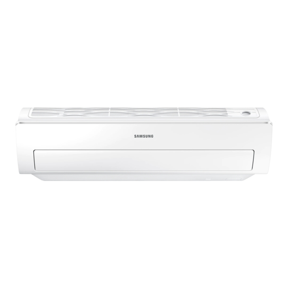
Page 13: At A Glance
Indoor Unit Overview The actual product may differ slightly from the image depicted below. 01 Air intake 06 Display 02 Air filter 07 Power button / Remote control receiver 03 Air flow blade (up and down) 08 (Inside) Virus doctor(AR✴✴HVSS✴✴) 04 Air flow blade (left and right) 05 Room temperature sensor Display (AR✴✴HVSS✴✴) - Page 14 Display (AR✴✴JVFS✴✴, AR✴✴KVFS✴✴, AR✴✴KVFN✴✴) 01 Operation indicator 02 Timer indicator good'sleep indicator Auto clean indicator 03 Single user indicator English DB68-06039A-00.indd 13 5/25/2016 7:08:32 PM...
-
Page 15: Remote Control Overview
Remote Control Overview 01 Set temperature indicator 02 Timer option indicator 03 Operation mode indicator 04 Options indicator 05 Low battery indicator 06 Transmit indicator 07 Fan speed indicator 08 Vertical air swing indicator 09 Settings indicator 10 Power button 11 Temperature button 12 Options button 13 Timer button... -
Page 16: Remote Control Operation
Remote Control Operation You can use the air conditioner easily by selecting a mode and then by controlling the temperature, fan speed, and air direction. Operation modes You can change the current mode between Auto, Cool, Dry, and Fan by pressing the button. -
Page 17: Vertical Air Flow
Controlling fan speed You can select the following fan speeds in each mode: Mode Available fan speeds Auto/Dry (Auto) (Auto), (Low), (Med), (High), Cool (Turbo) (Low), (Med), (High), (Turbo) Controlling air flow direction Vertical air flow Keep the vertical air flow in a constant direction by stopping the movements of the vertical air flow blade. -
Page 18: Power Smart Features
Power Smart Features Cooling Operation The smart and powerful cooling functions of the Samsung air conditioner keep an enclosed space cool and comfortable. Cool mode Use the Cool mode to stay cool in hot weather. ► ► Select Cool. NOTE •... -
Page 19: Dehumidifying Operation
Dehumidifying Operation The dehumidifying function of the Samsung air conditioner keeps an enclosed space dry and comfortable. Dry mode Use the Dry mode in rainy or humid weather. ► ► Select Dry. NOTE • The lower the set temperature is, the greater the dehumidifying capacity is. -
Page 20: Air Purifying Operation
Air Purifying Operation The air purification function of the Samsung air conditioner keeps the air in an enclosed space purified. Virus doctor function ( AR✴✴HVSS✴✴ Use the Virus doctor function to purify your room with positive ions produced by the air conditioner. This function is available in the Auto, Dry, and Fan modes. -
Page 21: Quick Smart Features
Quick Smart Features There is a variety of extra functionality provided by the Samsung air conditioner. Auto mode Use the Auto mode when you want the air conditioner to automatically control the operation. The air conditioner will provide the most comfortable atmosphere that it can. - Page 22 Fast function Use the Fast function to quickly cool your room. This function is the most powerful coolingfunction provided by the air conditioner. You can select this function in the Cool mode. ► ► ► In the Cool mode ► Select Fast.
- Page 23 Comfort function Use the Comfort function when you feel the current cooling effect is too strong. The air conditioner provides a mild cooling. You can select this function in the Cool mode. ► ► ► In the Cool mode ► Select Comfort.
- Page 24 Beep sound function Use the Beep sound function to turn on or off the beep sound that plays when you press a button on the remote control. ► ► ► Select Beep. English DB68-06039A-00.indd 23 5/25/2016 7:08:39 PM...
-
Page 25: Energy-Saving Features
Energy-Saving Operation The smart energy-saving functions of the Samsung air conditioner reduce electricity consumption. Single user function Use the Single user function to reduce electricity consumption while staying cool. You can select this function in the Cool mode. ► In the Cool mode NOTE •... - Page 26 Timed on/Timed off function Use the Timed on/Timed off to turn on or off the air conditioner after the time that you set. ► (Select On or Off among On, Off, and ► (Set the on/off time.) • Press the (Timer) button to change the current function between On, Off, and (good’sleep).
- Page 27 good’sleep function Use the good'sleep function to get a good sleep at night and to save energy. You can select this function in the Cool mode. In the Cool (Select among ► ► mode On, Off, and (Set the ► operation time.) •...
-
Page 28: Cleaning And Maintenance
Cleaning at a Glance Running Auto clean Cleaning duration (minutes) Auto (Cool), Cool, Dry NOTE • When you set the Auto clean timer, Clean blinks and then disappears on the remote control display. The Timer ( ) indicator also appears on the indoor unit display. •... -
Page 29: Cleaning The Filter
• When you clean and inspect the heat exchanger on the outdoor unit, contact the local service centre for help. • Make sure to prevent any injury from sharp edges of the surface when handling the heat exchanger. Cleaning the filter Vacuum cleaner Soft brush 30 minutes... -
Page 30: Troubleshooting
Troubleshooting If the air conditioner operates abnormally, refer to the following chart to save time and unnecessary expenses. Problem Solution • Check the power status, then operate the air conditioner again. • Switch on the circuit breaker, plug in the power cord, then operate The air conditioner the air conditioner again. - Page 31 Problem Solution The Timed on/off • Check whether you pressed the SET button on the remote control function does not after setting the time. work. The indicator • Press the Power button to turn off the air conditioner or disconnect blinks the power plug.
-
Page 32: Installation
• This manual explains how to install an indoor unit authorised centres or returned to the retailer so that with a split system with two SAMSUNG units. The use it can be disposed of correctly and safely. of other types of units with different control systems may damage the units and invalidate the warranty. - Page 33 • Our units must be installed in compliance with the smoothly. spaces indicated in the installation manual to ensure • If you have any difficulty finding installation location either accessibility from both sides or ability to as prescribed above, contact your manufacturer for perform routine maintenance and repairs.
-
Page 34: Preparation
Preparation Step 1.1 Choosing the installation CAUTION location • Comply with the length and height limits described in the figure above. Overview of installation location requirements Minimum clearances for the outdoor unit Wall 100 mm or more 125 mm 125 mm or more or more Minimum clearance in mm... -
Page 35: Step 1.2 Unpacking
When installing more than 1 outdoor unit (5 cases) Step 1.2 Unpacking (Unit: mm) Unpacking the indoor unit 1 Open the indoor unit package. 2 Remove the left and right cushions. 3 Pull out the unit from the package. 1500 3000 3000 Unpacking the outdoor unit... - Page 36 Optional accessories Accessories in the outdoor unit package Insulated assembly pipe, Rubber leg (4) Insulated assembly pipe, Ø 9.52 mm (1) Ø 6.35 mm (1) ✴✴09/10/12/13✴✴ Insulated assembly pipe, Insulated assembly pipe, NOTE Ø 12.70 mm (1) Ø 15.88 mm (1) •...
-
Page 37: Step 1.4 Drilling A Hole Through The Wall
Step 1.4 Drilling a hole through the 2 Drill the hole. wall CAUTION Before fixing the installation plate to a wall and then • Be sure to drill only one hole. fixing the indoor unit to the installation plate, a window frame, or a gypsum board, you must determine the •... -
Page 38: Indoor Unit Installation
Indoor Unit Installation Please scan this QR code for detail video of indoor unit installation. Step 2.1 Disassembling the cover panel 1 Remove the cap screws, then the screws. Cap screw Screw Step 2.2 Disassembling the installation plate Phillips screwdriver Flat-head screwdriver 2 Unlock the side hooks ( , ), then centre hooks ( ). -
Page 39: Step 2.3 Connecting The Power And Communication Cables (Assembly Cable)
Step 2.3 Connecting the power and • When performing electrical and earthing works, communication cables (assembly be sure to comply with the 'technical standards of cable) electrical installations' and the 'wiring regulations' in the local regulations. • Tighten the terminal block screw to 1.2-1.8 N•m (1.2- 1.8 kgf•cm). -
Page 40: Step 2.4 Optional: Extending The Power Cable
Step 2.4 Optional: Extending the 4 Using a compressor, compress the two points and flip it power cable over and compress another two points in the same location. • The compression dimension should be 8.0. 1 Prepare a compressor and the following tools. Tools Spec Shape... -
Page 41: Step 2.5 Installing And Connecting The Drain Hose
WARNING CAUTION • In case of extending the • Make sure that the indoor unit is in upright position electric wire, please DO when you pour water to check for leakage. Make sure NOT use a round-shaped that the water does not overflow onto the electrical pressing socket. -
Page 42: Step 2.7 Optional: Changing The Direction Of The Drain Hose
Step 2.7 Optional: Changing the Step 2.8 Installing and connecting direction of the drain hose the assembly pipes to the refrigerant pipes (assembly pipe) Connect indoor and outdoor units with field-supplied Drain pan outlet copper pipes by means of flare connections. Use Rubber cap insulated seamless refrigeration grade pipe only, (Cu DHP type according to ISO1337), degreased and... -
Page 43: Step 2.9 Shortening Or Extending The Refrigerant Pipes (Assembly Pipe)
1 Cut out the appropriate knock-out piece (A, B, C) on Step 2.9 Shortening or extending the the rear of the indoor unit unless you connect the refrigerant pipes (assembly pipe) pipe directly from the rear. 2 Smooth the cut edges. Pipe cutter 3 Remove the protection caps of the pipes and connect the assembly pipe to each pipe. -
Page 44: Step 2.10 Fixing The Installation Plate
CAUTION Step 2.10 Fixing the installation plate • If you need a pipe longer than specified in piping You can install the indoor unit on a wall, window frame, codes and standards, you must add refrigerant to the or gypsum board. pipe. -
Page 45: Step 2.11 Fixing The Indoor Unit To The Installation Plate
giving attention to the weight of the indoor unit. 3 Attach the installation plate to the wooden upright using tapping screws. When fixing the indoor unit on a gypsum board 1 Use stud finder to find out locations of the studs. 2 Fix the plate hanger on two studs. -
Page 46: Outdoor Unit Installation
Outdoor Unit Installation Step 3.1 Fixing the outdoor unit in Optional: Fixing the outdoor unit to a wall with a rack place Soft rubber designed to cut off vibration from rack to wall (not supplied with product) Rubber leg (Unit : mm) Model ✴✴09KV✴✴ME ✴✴10✴✴UN... -
Page 47: Step 3.3 Evacuating The Air
CAUTION • When installing, make sure there is no leakage. When recovering the refrigerant, ground the compressor first before removing the connection pipe. If the refrigerant pipe is not properly connected and the compressor works with the stop valve open, the pipe Control box inhales the air and it makes the pressure inside of Remove the screw for the... -
Page 48: Step 3.4 Adding Refrigerant
3 Open the valve of the low pressure side of manifold gauge anticlockwise. Siphon 4 Evacuate the air in the connected pipes using the vacuum pump for about 15 minutes. • Make sure that pressure gauge shows -0.1 MPa (-76 cmHg, 5 torr) after about 10 minutes. This Charge the refrigerant Charge the refrigerant turning standing the cylinder upright. -
Page 49: Installation Inspection
Installation Inspection Test parts for the indoor unit Step 4.1 Performing the gas leak tests 1 Before inspecting the leakage, use a torque wrench to close the cap for the stop valve. (Comply with a tightening torque for each size of the diameter, and Test parts for the indoor unit tighten the cap firmly to prevent any leakage.) - Page 50 When error occurs, take necessary measures by referring to the following table. For more information on necessary measures for errors, refer to the service manual. Error indicator LED Display Error Measures for the installer to take LED 1 LED 2 LED 3 Display Communication...
-
Page 51: Trial Operation
Step 4.3 Performing final check and 4 Turn off the air conditioner and switch mains supply off. trial operation 5 Disconnect tubing. After disconnection, protect valves 1 Check the following: and tubing ends from dust. • Strength of the installation site CAUTION •... - Page 52 English DB68-06039A-00.indd 51 5/25/2016 7:09:00 PM...