Table of Contents
Advertisement
Advertisement
Table of Contents

Related Manuals for Omega Engineering OMEGASCOPE OS523


Summary of Contents for Omega Engineering OMEGASCOPE OS523
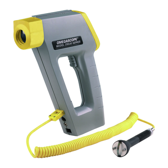
- Page 1 User’ s Guide MADE IN Shop online at omega.com e-mail: info@omega.com For latest product manuals: omegamanual.info Shown with Built-in Laser Sighting OS531, OS532, OS53x-CF, OS533, OS534, OS530L, OS530HR OS523, OS524 OMEGASCOPE ® Handheld Infrared Thermometer...
- Page 2 Toll Free in United Kingdom: 0800-488-488 e-mail: sales@omega.co.uk It is the policy of OMEGA Engineering, Inc. to comply with all worldwide safety and EMC/EMI regulations that apply. OMEGA is constantly pursuing certification of its products to the European New Approach Directives. OMEGA will add the CE mark to every appropriate device upon certification.
- Page 3 Unpacking Instructions Notes...
- Page 4 Remove the Packing List and verify that you have received all equipment, including the following (quantities in parentheses): • OS530/OS520 Series Handheld Infrared Thermometer (1) • AA Size Lithium Batteries (4) • Soft Cover Carrying Case (1) • Analog Cable (1) •...
-
Page 6: Table Of Contents
Parts of the Thermometer 1.2.1 Front of the Thermometer 1.2.2 Rear of the Thermometer Chapter 2 Using the Handheld Infrared Thermometer ..2-1 How to Power the Thermometer 2.1.1 Battery Operation 2.1.2... - Page 7 TABLE OF CONTENTS Appendix A How Infrared Thermometry Works ... . . A-1 Appendix B Emissivity Values ......B-1 Appendix C Determining an Unknown Emissivity .
-
Page 8: General Description
• Food Processing: Taking accurate temperature readings without direct contact with the food or packaging material. The IR thermometer provides information at a glance — the custom backlit dual digital LCD displays both current and minimum, maximum, average or differential temperatures. This versatile instrument provides: •... -
Page 9: Chapter 1 General Description
• Sealed keypad display. • Convenient trigger operation. • Soft carrying case and wrist strap, for safety and ease of carrying. • Rubber boot around the lens and the display. Table 1-1. OS530 Series Handheld Infrared Thermometer Features Features Accuracy* Range Emissivity... - Page 10 Features OS530L Accuracy* ±1% rdg Range -18 to 538°C -30 to 121°C -18 to 538°C -18 to 538°C -18 to 871°C 0 to 1000°F Emissivity Adjustable Display Resolution 1°F or 1°C Backlit Dual Display Field of view 10:1 Differential Temperature Min/Max Temperature Average...
- Page 11 General Description Features Accuracy Range Emissivity Backlit Dual Display Distance to Spot Size Ratio Differential Temperature Min/Max Temperature Average Temperature High Alarm Low Alarm Audible Alarm & Indicator Ambient Target Temperature Compensation Analog Output RS-232 Output Thermocouple Input Data Storage Built-in Laser Sighting Trigger Lock Last Temperature Recall...
-
Page 12: Parts Of The Thermometer
1.2 Parts of the Thermometer 1.2.1 Front of the Thermometer °F Figure 1-1. OS530/OS520 Series Handheld Infrared Thermometer Front View The display is shown in more detail in Figure 1-2 and described in Table 1-2. There are no user-serviceable parts in the thermometer. - Page 13 General Description Figure 1-2. Display and Keypad View ➀ Display Mode displays one of the following: E (Emissivity) MAX (Maximum Temperature) MIN (Minimum Temperature) dIF (Differential Temperature) AVG (Average Temperature) ➁ Data associated with one of the Display Modes ➂ Backlighting Icon - allows the display to be viewed under low ambient light ➃...
-
Page 14: Rear Of The Thermometer
1.2.2 Rear of the Thermometer Figure 1-3 shows the various jacks that are used to connect a recorder or the ac adapter to the thermometer. The figure also shows the location of the tripod thread mount used for fixed point monitoring. - Page 15 General Description Notes...
-
Page 16: How To Power The Thermometer
2.1 How to Power the Thermometer 2.1.1 Battery Operation Invert the thermometer and install 4 fresh AA size batteries as shown in Figure 2-1. Make sure the batteries’ polarities are correct, the batteries are not put in backwards, and are of the same type. -
Page 17: Chapter 2 Using The Handheld Infrared Thermometer
Laser Sighting. Figure 2-2. OS530/OS520 Series with Built-in Laser Sighting 2. The field of view of the thermometer should fall within the area of the target being measured. See Figure 2-3. Figures 2-4 through 2-6 show the field of view vs distance for the various thermometers. - Page 18 Using the Handheld Infrared Thermometer Figure 2-4. Field of View OS531, OS532, OS530L DISTANCE: SENSOR TO OBJECT (FT) 20" 4.8" 4.2" 3.6" 1.0" @ 0" to 20" 3.0" 2.4" 1.8" 1.0" 1.2" 1.0" D:S = 20:1 2.5cm @ 51cm 10.0 *SPOT DIAMETER MEASURED 12.2...
- Page 19 Using the Handheld Infrared Thermometer Figure 2-6 Field of View OS534, OS523-1 DISTANCE: SENSOR LENS TO OBJECT (in.) 6" 15" 3" 9" 12" 1.17" .78" 0.9" .39" .45" .15" D:S = 40:1 11.5 19.9 29.9 *SPOT DIAMETER MEASURED AT 90% ENERGY 15.2...
- Page 20 Using the Handheld Infrared Thermometer DISTANCE: SENSOR TO OBJECT (FT) 0.9"@ 0 1.2" 1.0" 0.9" 22mm @ 0 *SPOT DIAMETER MEASURED AT 90% ENERGY DISTANCE: SENSOR TO OBJECT (M) Figure 2-8 Field of View OS523-2 DISTANCE: SENSOR TO OBJECT (FT) 3’...
- Page 21 Laser Sighting as well as the display backlight will stay on . 5. After completing a temperature measurement, release the trigger. In order to conserve battery life, the thermometer goes into sleep mode and the Laser Sighting turns off. DISTANCE: SENSOR TO OBJECT (FT) 5.1"...
-
Page 22: Measurement Techniques
2.2.1 Measurement Techniques You can use the IR Thermometer to collect temperature data in any one of five different ways: • Spot Measurement — Measures the temperature of discrete objects such as motor bearings, engine exhaust manifolds, etc.: Aim at the desired target and pull the trigger. - Page 23 Using the Handheld Infrared Thermometer • Moving Surface Scan - Measures the Temperature of Points on a Moving Surface: Mount the thermometer on a camera tripod and aim at a fixed point on the moving surface. Pull the trigger and press the If necessary, adjust the emissivity.
-
Page 24: Real Time Mode (Active Operation)
2.3 Real Time Mode (Active Operation) Definition: Real Time Mode is the active operational mode of the thermometer. In this mode, the thermometer constantly measures and displays temperature. Figure 2-12. General Operational Block Diagram If the trigger is pulled two times in rapid sequence, it may reset the emissivity, high alarm, low alarm and target ambient temperature to the default values. - Page 25 Using the Handheld Infrared Thermometer Table 2-1. Functional Flow Chart when the Trigger is Pulled (Real Time Mode) OS530HR OS530L, OS532 & OS531 OS533 OS524 OS523, OS534, 2-10...
- Page 26 Using the Handheld Infrared Thermometer MODE DISPLAY ☞ ☞ ☞ ☞ ☞ ☞ ☞ Figure 2-13. Visual Function Flow Chart While in these 5 modes: key to change temperature from °F to °C or vice versa. key to turn on the display backlighting.
-
Page 27: Adjusting Emissivity
This function electronically locks the trigger mechanism: 1. Pull the trigger and press the icon will appear on the display. 2. Release the trigger. This allows the thermometer to operate continuously whether or not the trigger is pulled. To unlock the trigger function, press the... -
Page 28: Calculating Temperature Values
°F °F To clear the “AVG ---” display, turn off the thermometer. Every time the thermometer goes from the sleep mode to the Real Time mode (by pulling the trigger) the MAX, MIN, dIF, AVG and TC temperatures are updated. -
Page 29: Thermocouple Input
Using the Handheld Infrared Thermometer 2.3.6 Thermocouple Input (OS532, OS533, OS534) The thermometer accepts thermocouple input. It displays thermocouple temperature and the target temperature (via infrared) simultaneously. This function provides an accurate method of determining an unknown emissivity. °F • To Determine an unknown target emissivity... -
Page 30: Using The Alarm Functions
2.3.7 Using the Alarm Functions The thermometer provides audible and visible alarm indications. • To set the high alarm value: °F Pull the trigger. Then press and hold the the High Alarm Display Mode (HAL) appears. Press the Press the... - Page 31 NOTE The low alarm setpoint does not change when the thermometer is turned off. However, when the batteries are replaced, it is reset to the default value of 0°F (1000°F for OS524). key until...
-
Page 32: Using Ambient Target Temperature Compensation
Set the emissivity to 1.0 (refer to Section 2.3.1). Press and hold the Mode (AVG) appears. Slowly move the thermometer so that the line of sight sweeps across the area surrounding the target. The thermometer measures the temperature at each point on the surrounding area. - Page 33 Using the Handheld Infrared Thermometer °F 2.3.9 Sending Temperature Data to a Serial Printer (OS533, OS534, OS523, OS524) The thermometer can transmit temperature data to a Serial Printer via the RS-232 phone jack and the RS-232 cable. °F 2-18 Press and hold the Mode (E) appears.
- Page 34 °F Thermometer To stop sending data, press the Using the Handheld Infrared Thermometer NOTE Bottom hole is the RS-232 jack RS-232 Digital Cable 6-pin Phone Jack To the Figure 2-14. Serial Printer Hookup Pull the trigger and press the trigger. The icon will appear on the display.
-
Page 35: Sending Temperature Data To A Personal Computer
Using the Handheld Infrared Thermometer °F 2.3.10 Sending Temperature Data to a Personal Computer (OS533, OS534, OS523, OS524) The thermometer can transmit temperature data to a Personal Computer via the RS-232 phone jack and the °F RS-232 cable. 2.3.10.1 Software Installation... - Page 36 8. After a successful installation, the installer program will notify you with a pop-up which states "IR_TEMPSOFT from Omega Engineering Setup was completed successfully." Just click on the "OK" button. If you have any trouble with the installation of this...
- Page 37 PC can cause damage to communications ports, or other electronic circuitry in your device or computer. 1. With the thermometer device powered down, connect the enclosed serial communications cable to the device. 2. Connect the other end of the serial cable to the desired communications port of the personal computer.
- Page 38 Using the Handheld Infrared Thermometer waiting for the thermometer to transmit data through your RS-232 port. 4. Begin transmitting data from the thermometer by pressing and holding the until the Print Data Display Mode (PRN) appears. 5. Press the "UP" key to increment the printing interval.
-
Page 39: Storing The Temperature Data On Command
Using the Handheld Infrared Thermometer 2.3.11 Storing the Temperature Data on Command (OS534, OS523, OS524) The thermometer can store up to 100 temperature data points on command. Each set of temperature data is broken °F down into the temperature value, emissivity, and high alarm setpoint for that temperature. - Page 40 1 and 2 The display freezes momentarily, and a beep sounds for about 1 second. Now the memory is cleared. The thermometer reverts to real time mode. Erasing the temperature data does not erase or reset Emissivity, High and Low Alarm setpoints,...
-
Page 41: Recall Mode (Passive Operation)
Using the Handheld Infrared Thermometer 2.4 Recall Mode (Passive Operation) Definition: Recall Mode is the passive operational mode of the thermometer. In this mode, you may review the most recently stored temperature data and parameters. Pull Trigger Real Time (Table 2-1) Mode (Active) Figure 2-16. - Page 42 Using the Handheld Infrared Thermometer Table 2-2. Functional Flow Chart (Recall Mode) OS530HR OS530L, OS532 & OS531 OS533 OS524 OS523, OS534, 2-27...
-
Page 43: Reviewing The Last Parameters
Using the Handheld Infrared Thermometer 2.4.1 Reviewing the Last Parameters The thermometer stores the last temperature measured in the real time mode (refer to Table 2-1). This temperature °F can be recalled by pressing the - Press the temperature data and parameters. You may review: 3.6.2 Downloading Previously Stored Temperature Data... - Page 44 To download stored temperature data points from the thermometer, first make certain that it is not in printing °F mode. Make sure that the IR_TEMPSOFT is installed properly as explained in section 2.3.10. On the main menu bar, click on “Command-> Download Stored Data”.
-
Page 45: Reviewing Previously Stored Temperature
(OS534, OS523, OS524) You can review all 100 stored temperature values on the thermometer display using the following procedure: °F If no keys are pressed, the thermometer goes into sleep mode in approximately 10 seconds. 2-30 Press and hold the Display Mode (MEM) appear. -
Page 46: Chapter 3 Laser Sighting
3.1 Warnings and Cautions You may receive harmful laser radiation exposure if you do not adhere to the warnings listed below: • USE OF CONTROLS OR ADJUSTMENTS OR PERFORMANCE OF PROCEDURES OTHER THAN THOSE SPECIFIED HERE MAY RESULT IN HAZARDOUS RADIATION EXPOSURE. -
Page 47: Description
OS53x-CF and OS523-3 — Thermometer with built-in Laser Dot All other models — Thermometer with built-in Laser Dot/Circle Switchable Figures 3-1 and 3-2 show the rear and front view of the thermometer with the built-in laser sight module. Laser... -
Page 48: Operating The Laser Sighting
The laser dot provides visibility at longer distances. Figure 3-3 shows the two different laser configurations. The laser Dot indicates the center of the field of view of the thermometer. The laser Circle indicates the perimeter of the thermometer’s field of view. - Page 49 The Laser Sighting turns on only when used with the thermometer. The module does not turn on by itself. The line of sight of the thermometer does not coincide with that of the Laser Sighting, as shown in Figure 3-4. The two lines of sight become less critical when measuring distant targets.
-
Page 50: Installing And Operating The Sighting Scope
4.1 Sighting Scope The Sighting scope is an accessory for the thermometer. It provides a visual indication of the target being measured. Aiming at distant targets (up to 200 feet) becomes much easier by using the Sighting scope. 4.2 Installing and Operating the Sighting Scope 1. - Page 51 Sighting Scope Line of sight of Pair of Mounting Clamps the sighting scope 1 11/16 (42.8 mm) Line of sight of the thermometer Figure 4-1. Installing the Sighting Scope...
-
Page 52: Chapter 5 Maintenance
BEFORE replacing the batteries. The thermometer is powered by 4 standard AA size lithium batteries. To replace the batteries: 1. Invert the thermometer and open the cover of the battery compartment. 2. Remove the old batteries. 3. Install 4 fresh AA size (lithium or alkaline) batteries as shown in Figure 2-1. -
Page 53: Cleaning The Lens
Do not wipe the surface dry, as this may cause scratching. 5.3 Calibrating the Thermometer The thermometer can not be calibrated by the user. For precise calibration of the thermometer, call our Customer Service Department. It is recommended that the Infrared Thermometer to be sent to the factory once a year for recalibration. -
Page 54: Troubleshooting Guide
- remove and reinstall the batteries. Make sure that the trigger is pulled completely. Reset the thermometer. It sets all of the parameters to the default values and restores calibration. The procedure is as follows, when the thermometer is in sleep mode: a. - Page 55 Solution Remove and reinstall the batteries or disconnect and reconnect the ac adapter. Clean the thermometer lens. Refer to Section 4.2. Activate the Diagnostic Program in the thermometer as follows: a. Pull the trigger and press the key to lock the trigger.
- Page 56 The Customer Service Department representative may ask you to return the thermometer to the factory. • The display will go back to the Real Time Mode (Emissivity Display Mode).
- Page 57 Troubleshooting Guide Problem The thermometer resets itself unexpectedly. The emissivity has been reset to .95. All other parameters are reset to the default values. Laser Sighting Problem No Laser Beam The Laser "line of sight" does not coincide with the center of the target.
-
Page 58: Specifications
(Specifications are for all models except where noted) THERMOMETER Measuring: Temperature Range: Accuracy (24°C or 75°F Ambient Temperature and at emissivity of 0.95 or greater): Field of Vision: Repeatability: Resolution: Response Time: Spectral Response: Thermocouple Input Input Connection Thermocouple Display Accuracy @ 75°F (24°C) - Page 59 Each set of data consists of the temperature, the Emissivity and the high alarm value. ”V” groove on top of the thermometer or use Laser Sighting 1 mV/°F or 1 mV/°C, set via keypad (0.5 mV/Deg, OS524)
- Page 60 Laser Sighting): 17 hours (continuous operation) 30 hours (continuous operation) 3 days (continuous operation) ⁄ ”-20 UNC Attached to the thermometer case Standard 8.6" x 6.6" x 2.0" (218.4 x 167.6 x 50.8 mm) 1.3 lbs (0.585 kg) Specifications...
- Page 61 Operating Relative Humidity: 95% or less without condensation Power Switch: Power Indicator: Power: Identification Label: Warning & Certification Label: Located on the left side of the thermometer 630-670 nanometers (red) 2 to 40 ft. 2 to 15 ft. Class II Laser Product...
- Page 62 Key(s) Press and hold down the key & then press the keys Glossary of Key Strokes Key(s) Functions • Selects one of the following Display Modes: E , MAX, MIN, dIF, AVG, TC, HAL, LAL, AMB, PRN or MEM. • Locks/unlocks the trigger.
- Page 63 Glossary of Key Strokes Notes...
-
Page 64: Appendix A How Infrared Thermometry Works
Figure A-1 shows a block diagram of an infrared radiation thermometer. Energy from the object is focused by the lens onto the detector. As the detector heats up, it sends out an electrical signal, which in turn is amplified and sent to the circuitry of the thermometer. - Page 65 Appendix: How Infrared Thermometry Works Blackbody When thermal radiation falls on an object, part of the energy is transmitted through the object, part is reflected and part is absorbed. A blackbody is defined as an ideal object that absorbs all the radiation incident upon it.
- Page 66 T = temperature of object in Kelvin = temperature of ambient surroundings in Kelvin The infrared thermometer uses this equation directly in calculating the temperature of an object. The incident power is measured by the infrared detector. The emissivity of the object is determined by the user.
- Page 67 FOV, within which they see all objects. In particular, the thermometer will measure a fixed proportion of the energy radiated by all objects within its FOV. The user must guarantee that the distance between the thermometer and the object is defined so that only that object fills the FOV of the instrument.
-
Page 68: Appendix B Emissivity Values
Appendix: Emissivity Values Table B-1 provides guidelines for estimating the emissivity of various common materials. Actual emissivity, especially of metals, can vary greatly depending upon surface finish, oxidation, or the presence of contaminants. Also, emissivity or infrared radiation for some materials varies with wavelength and temperature. - Page 69 Appendix: Emissivity Values Material Emissivity (ε) Asbestos Board ......... . 0.96 Asphalt, tar, pitch .
-
Page 70: Appendix C Determining An Unknown Emissivity
Heat the object (or at least a sample of the object material) on top of a heating plate to a known temperature. Make sure the thermometer and the air surrounding the heating plate are at the same temperature. Measure the temperature of the object material with the thermometer. - Page 71 FOV of the thermometer. Area 'A' Target Aim the thermometer at Area ‘B’ as shown in Figure C-1 Make sure that Area ‘B’ is as close as possible to Area ‘A’. Adjust the emissivity of the thermometer until the temperature reading equals the temperature found in Step 3.
- Page 72 C-1. Make sure that the painted area of object material fills the FOV of the thermometer. Aim the thermometer at another spot on the target - Area ‘B’ in Figure C-1. Adjust the emissivity of the thermometer until the temperature reading equals the temperature found in Step 2.
- Page 73 Appendix: Determining an Unknown Emissivity Notes...
-
Page 74: Index
ac Adapter Input Jack ... 1-6 Active Operation ... 2-8 Aiming Sight “V Groove” ... 1-4 Alarms ... 2-14, 2-15 Alkaline Batteries ... 2-1, 4-1, 6-3 Ambient Target Temperature Compensation ... 2-16 Analog Output Jack ... 1-6 Backlighting Icon ... 1-5 Battery(s): Compartment ... - Page 75 Power Button ... 2-2, 3-2 Problems ... 5-1 - 5-4 Power Indicator LED... 2-2, 3-2 Removing from Thermometer ... 3-4, 3-5 Warnings and Cautions ... 3-1 LCD, Backlit ... 1-4 Lens Cleaning ... 4-2 Lines of Sight of the Module and Thermometer ...
- Page 76 Stefan-Boltzmann Law ... A-3 Storing Temperature Data ... 2-23 Temperature Data: Erasing ...2-24 Storing ... 2-23 Thermal Radiation ... A-1 Thermometer: Front View...1-4 Rear View ...1-6 Tripod Thread Mount ... 1-4, 1-6 “V” Groove Aiming Sight ... 1-4 Wein’s Displacement Law ... A-3 Wrist Strap ...
- Page 77 OMEGA ENGINEERING, INC. warrants this unit to be free of defects in materials and workmanship for a period of 25 months from date of purchase on the base unit and 13 months from date of purchase on Laser Sight Module.
- Page 78 Where Do I Find Everything I Need for Process Measurement and Control? OMEGA…Of Course! Shop online at omega.com TEMPERATURE Thermocouple, RTD & Thermistor Probes, Connectors, Panels & Assemblies Wire: Thermocouple, RTD & Thermistor Calibrators & Ice Point References Recorders, Controllers & Process Monitors Infrared Pyrometers PRESSURE, STRAIN AND FORCE Transducers &...