
Related Manuals for Omega PRESSURE GAUGES DPG5000


Summary of Contents for Omega PRESSURE GAUGES DPG5000
- Page 1 User’s Guide http://www.omega.com e-mail: info@omega.com DPG5000 PRESSURE GAUGES M3366/0606...
- Page 2 Where Do I Find Everything I Need for Process Measurement and Control? OMEGA...Of Course! TEMPERATURE ✓ Thermocouple, RTD & Thermistor Probes, Connectors, Panels & Assemblies ✓ Wire: Thermocouple, RTD & Thermistor ✓ Calibrators & Ice Point References ✓ Recorders, Controllers & Process Monitors ✓ Infrared Pyrometers PRESSURE, STRAIN AND FORCE ✓ Transducers & Strain Gages ✓ Load Cells & Pressure Gages ✓ Displacement Transducers ✓ Instrumentation & Accessories FLOW/LEVEL ✓ Rotameters, Gas Mass Flowmeters...
-
Page 3: Table Of Contents
M3366/0606 DPG5000 Table of Contents Warranty/Disclaimer..2 Return.Requests/Inquiries..3 Instructions...4 . Zero.Trimming..4 . Use.of.Auto-Tare.Feature...4 . Battery.Replacement...4 . Re-Calibration...5 . Use.Of.Peak-Hold.Feature.(Optional)...5 . Analog.Output.Option.(0.To.2.VDC)...5 . 4-20.mA.Transmitter.Option...6 . External.Power.(24.VDC).and. . 0.to.5.VDC.Analog.Output.Option..7 . External.Power.Without.Other.Options...7... -
Page 4: Warranty/Disclaimer
In no even shall OMEGA be liable for consequential, incidental or special damages. -
Page 5: Return.requests/Inquiries
M3366/0606 • Return Requests/Inquiries Direct all warranty and repair requests/inquiries to the OMEGA Customer Service Department. BEFORE RETURNING ANY PRODUCT(S) TO OMEGA, PURCHASER MUST OBTAIN AN AUTHORIZED RETURN (AR) NUMBER FROM OMEGA’S CUSTOMER SERVICE DEPARTMENT (IN ORDER TO AVOID PROCESSING DELAYS). The assigned AR number should then be marked on the outside of the return package and on any correspondence. The purchaser is responsible for shipping charges, freight, insurance and proper packaging to prevent breakage in transit. Warranty Returns For WARRANTY RETURNS, please have the following information available BEFORE contacting OMEGA: 1. Purchase Order number under which the product was PURCHASED, 2. Model and serial number of the product under warranty, and 3. Repair instructions and/or specific problem relative to the product. Non-Warranty Repairs For NON-WARRANTY REPAIRS, consult OMEGA for current repair charges. Have the following information available BEFORE contact OMEGA: 1. Purchase Order number to cover the COST of the repair, 2. Model and serial number of the product, and 3. Repair instructions and/or specific problem relative to the product. DPG5000... -
Page 6: Instructions
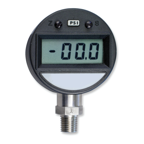
DPG5000 • Instructions NOTE:.All.units.are.factory.calibrated.prior.to.shipment. 1. Zero Trimming NOTE:.Some.units.are.equipped.with.zero.“knob”. If it becomes necessary to re-adjust the “Zero” on the display, this can be accomplished by turning the trimpot marked “Z” just to the left of the On/Off push button. On the DPG5000 there is either a zero adjustment knob or a black nylon cover screw. If the gauge has a cover screw, it is necessary to remove the cover screw to access the zero adjustment pot. An ideal zero is indicated by a reading of 000 with an intermittently flashing “-” sign. NOTE:.A.jewelers.screwdriver.or.an.eyeglass.repair.screwdriver.(supplied). is.a.suitable.instrument..Do.not.make.changes.to.the.Span.adjustment.(the.“S”. pot.to.the.right.of.the.push.button).as.part.of.the.zero.trimming..The.Span.should. only.be.changed.as.part.of.the.re-calibration.of.a.gauge.with.a.known.pressure. source. 2. Use of Auto-Tare Feature When the DPG5000 is first turned on you will notice that the display flashes for the first 4 seconds. If the On/Off button is pushed and held during this period, any existing reading will be re-set to zero. This allows the user to “Tare- Out” a starting weight in hydraulic weighing applications. To remove the Tare feature turn the unit off and back on again and do not push the On/Off button during the flashing period. 3. Battery Replacement (9 Volt Type) The battery can be replaced simply by removing the single screw at the top of the battery door. Remove the old battery, unplug the cable connector and replace with Eveready type 216 or equivalent. Replace the battery door and secure with the self-tapping screw. (Do not overtighten) NOTE:.For.best.accuracy,.re-calibration.per.step.4.should.be.performed.at.the. -
Page 7: Re-Calibration
M3366/0606 4. Re-Calibration This procedure requires a known pressure source of at least ±0.1% accuracy in order to fully utilize the accuracy potential of the DPG5000 (If not available, the gauge can be returned to OMEGA for re-calibration.) Procedure: A. Ensure the Gauge is at 0 psig (or vacuum if absolute), and adjust the zero as per instructions in step 1. B. Apply full scale pressure to the pressure port and adjust the span (“S”) pot until the display reads the correct pressure. C. Re-check the zero and re-adjust the zero (“Z”) pot if required. D. Repeat steps B and C, until no further adjustment is required. 5. Use Of Peak-Hold Feature (Optional) After initially turning the gage on (wait until the display stops flashing), a second push of the On/Off button energizes the peak-hold feature and causes an arrow to appear in the display. In this mode, only the highest reading sensed will be shown (until a higher reading comes along). This “peak” reading will be retained until the unit is reset by turning it off with a third push of the button. The sequence can then be re-initiated; one push for on in normal mode, two pushes for “peak-hold” mode and a third push for Off/Re-set. 6. Analog Output Option (0 To 2 VDC) The 0–2 VDC analog output is accessed through a miniature “Phone Jack” (mate supplied) on the back of the unit (see External Power and 0-2 VDC Output Plug drawing on the last page). The “Tip” connection is “+ Output”... -
Page 8: 4-20.Ma.transmitter.option
DPG5000 7. 4-20 mA Transmitter Option When equipped with this option the gauge no longer operates from batteries but instead is “Loop Powered”. The loop connection is made to a 6 pin receptacle located at the rear of the unit (a mating plug is supplied). A voltage of between 9 and 32 VDC must be maintained at this connection (Pin A is “+” and Pin B is “-” see sketch) to insure proper operation. Completion of the earth or system ground (Pin F) is recommended for proper circuit protection. Power supply voltage must be sufficient to maintain a minimum of 9 VDC at the gauge terminals after “dropping” voltage across RL at full scale current (20 mA). Example: If RL = 250 ohm then “drop” is 0.02 Amps X 250 ohm = 5 volts. Therefore power supply minimum is 5 V + 9 V = 14 V. RE-CALIBRATION: The procedure is the same as in step 4, except that there are 2 sets of zero and span adjustments. The front panel controls affect the display and the rear controls (remove “battery” door) affect the 4/20 mA signal. Typical 4-20 mA Circuit Gauge Connector + EXCITATION – EXCITATION 4-20 mA CURRENT LOOP M3366/0606 Process Controller +Vin... -
Page 9: External.power.(24.Vdc).And
M3366/0606 8. External Power (24 VDC) and 0 to 5 VDC Analog Output Option When equipped with this option the gauge no longer operates from batteries but instead is “externally powered”. Both the 24* VDC input power and the 0 to 5 VDC Analog Output are connected to the 6 pin circular connector on the rear of the unit. Pin connections are as follows: *Actual.range.of.input.voltage.is.12.to.31.VDC. 24 VDC External Power and 0-5 V Analog Output PIN -A- PLUS (+) 24 VDC POWER IN PIN -B- PLUS (+) ANALOG OUTPUT PIN -C- MINUS (-) ANALOG OUTPUT PIN -D- MINUS (-) 24 VDC POWER IN PIN -E- NO CONNECTION PIN -F- CASE GROUND 9. External Power Without Other Options The external power input is accessed through a miniature “Phone Jack”... - Page 10 DPG5000 M3366/0606 Notes...
- Page 11 Thank You for Purchasing OMEGA Products OMEGA’s policy is to make running changes, not model changes, whenever an improvement is possible. This affords our customers the latest in technology and engineering. It is the policy of OMEGA to comply with all worldwide safety and EMC/ EMI regulations that apply. OMEGA is constantly pursuing certification of its products to the European New Approach Directives. OMEGA will add the CE mark to every appropriate device upon certification. The information contained in this document is believed to be correct, but OMEGA Engineering, Inc. accepts no liability for any errors it contains, and reserves the right to alter specifications without notice. WARNING: These products are not designed for use in, and should not be used for, patient-connected applications. Again, thank you for your interest in OMEGA. We welcome the opportunity to help you achieve your application goals.
- Page 12 On-Line Service ® www.omega.com USA: One Omega Drive, P.O. Box 4047 Stamford, CT 06907-0047 ISO.9001.Certified TEL: (203) 359-1660 e-mail: info@omega.com Canada: 976 Bergar Laval (Quebec) H7L 5A1 TEL: (514) 856-6928 e-mail: info@omega.ca For immediate technical or application assistance: USA and Canada: Sales Service: 1-800-826-6342 / 1-800-TC-OMEGA Customer Service: 1-800-622-2378 / 1-800-622-BEST Engineering Service: 1-800-872-9436 / 1-800-USA-WHEN TELEX: 996404 EASYLINK: 62968934 CABLE: OMEGA Mexica: Tel: (001) 800-826-6342 En Español: (001) 203-359-7803 Benelux: Postbus 8034, 1180 LA Amstelveen, The Netherlands TEL: +31 (0) 20 6418405 Toll Free in Benelux: 0800 0993344 e-mail: nl@omega.com Czech Republic: Rudé armády 1868, 733 01 Karviná TEL: +420 (0) 69 6311899 Toll Free in Czech Rep.: 0800-1-66342 e-mail: czech@omega.com...