Table of Contents
Advertisement
Quick Links
Advertisement
Table of Contents

Related Manuals for Omega 3200


Summary of Contents for Omega 3200
- Page 1 FMA 3200/3200ST/3400/3400ST Series Thermal Mass Flow Controllers...
-
Page 3: Table Of Contents
READ THIS MANUAL COMPLETELY BEFORE ATTEMPTING TO CONNECT OR OPERATE YOUR FLOW SENSOR. FAILURE TO DO SO MAY RESULT IN INJURY TO YOU OR DAMAGE TO THE FLOW CONTROLLER. T A B L E Introduction ... 4 1. Unpacking ... 4 2. -
Page 4: Introduction
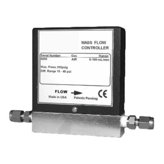
The products should also be checked for any concealed shipping damage. If any shortages or damage is noted, please contact Omega Engineering to resolve the problem. Typical Contents of Box: Controller, Calibration Certificate & Manual FMA 3200/3200ST shown;... -
Page 5: Installation
A patented system insures that the zero remains stable and the sensor is extremely repeatable. Flow in the FMA 3200/3400 Series is controlled by a proportional solenoid valve with active servo electronics. The flow measurement signal is analyzed by micro-processor controlled electronics and compared to a set- point. - Page 6 unit may be damaged or fail prematurely. Such damage will not be repaired under warranty. Units should be installed in a clean, dry environment with an ambient temperature that is as stable as possible. Avoid areas with strong magnetic fields, strong air flows or excessive vibration. In order to operate the differential pressure across the controller should be in the range 15-45psid (1-3 bar).
-
Page 7: Mounting The Flow Controller
Mounting the Flow Controller. The FMA 3200/3400 Series controllers have no particular orientation or installation requirements so may be mounted in any convenient position. It is recommended that units be fixed to a suitable substrate using the two 4-40 mounting holes provided. -
Page 8: Electrical Connections
Overview The FMA 3200/3400 Series provides a 0-5VDC analog output proportional to the flow rate. This output may be connected to a display, data acquisition system or voltmeter with an impedance of greater than 2.5 kΩ... -
Page 9: B) Connecting The 6 Pin Mini Din Connector
Connecting The 6 Pin Mini Din Connector Using a suitable mating connector the pins of the integrated connector should be wired as follows: Connecting To The Integrated 6 Pin Connector Pin 2 should be connected to the Positive of the power source. Pin 6 should be connected to the Negative (Ground) of the power source. -
Page 10: C) Connecting The 6 Pin Mini Din Connector & Fma 3000C Cable
Connecting The 6 Pin Mini Din Connector & FMA 3000C Cable The two mating connectors should be pushed together and the pigtail leads wired as follows: Connecting To The Integrated 6 Pin Connector Using A FMA 3000C Cable The RED wire should be connected to the Positive of the power source. The BLACK wire should be connected to the Negative (Ground) of the power source. -
Page 11: D) Connections For The 9 Pin D Sub Connector
Connections For The 9 Pin D Sub Connector Using a suitable mating connector the pins of the integrated connector should be wired as follows: Connecting To The Integrated 9 Pin Connector PIN 3 should be connected to the Positive of the power source. PIN 4 should be connected to the Negative ( Ground ) of the power source. -
Page 12: E) Connections For The 15 Pin D Sub Connector
Connections For The 15 D Sub Connector Using a suitable mating connector the pins of the integrated connector should be wired as follows: Connecting To The Integrated 15 Pin Connector PIN 7 should be connected to the Positive of the power source. PIN 5 should be connected to the Negative ( Ground ) of the power source. -
Page 13: F) Using A 0-5Vdc Output / Input Power Adapter Package
Using a 0-5VDC Input / Output Power Adapter Package. An optional 0-5VDC Input / Output Power Adapter Package is available for use with the FMA 3200/3400 Series. This consists of a power source (115VAC or 230VAC), a connection hub and two cable assemblies with pig- tail (soldered wire) ends. -
Page 14: Operation
Operation Warm Up Before applying power to the unit check all tubing and electrical connections. Once correct installation is verified switch on the power. The unit should then be allowed to warm up for 5 minutes before gas pressure is applied. Verification of Zero Flow through the unit should be stopped by sealing or capping the inlet of the controller. -
Page 15: Changing The Flow Rate Set-Point (Using An External Voltage Source)
is the flow rate of the new gas is the flow rate of the original calibration gas is the K factor of the new gas is the K factor of the original calibration gas = (K If K is larger than K then linear results will only be achieved if the unit does not exceed 5(K )VDC for the full scale output. -
Page 16: Changing The Flow Rate Set-Point - Fma3400 / 3400St Only
Power Save Mode. To improve valve performance and reliability over time, the FMA 3200/3400 Series features a Power Save Mode. This is activated after a prolonged application of a zero or negative set-point. When a control voltage greater than 0 VDC is applied after the Power Save Mode has been initiated there may be a short delay (1-2 secs) before the valve actuates. -
Page 17: Zero Adjustments
Recalibration If recalibration is required please contact the Omega Engineering Customer Service Department. Changing the Calibration Gas – FMA 3400/3400ST Series Only The FMA 3400/3400ST Series may be calibrated for up to three gases. -
Page 18: Maintenance And Product Care
Returning Units for Repair or Recalibration To return a unit for repair or recalibration please contact the Omega Engineering Customer Service Department. An Authorized Return (AR) number will then be issued. The AR number should then be noted on the outside of the package and on any correspondence. -
Page 19: Specifications
Consumption Electrical Connections Certifications *Specifications from 10-100% of rated flow. Linearity is best fit straight line. All calibrations performed with air unless otherwise stated on calibration certificate. FMA 3200 FMA 3400 FMA 3200ST ±1.5% of ±1.5% of ±1.5% of Full Scale*... -
Page 20: Dimensions
Dimensions ALL DIMENSIONS IN INCHES (MILLIMETERS IN BRACKETS) FMA 3200/3200ST Series - 1/4” Stainless Fittings Shown M-4271/0707, pg. 20 of 26... - Page 21 FMA 3400/3400ST Series - 1/4” Stainless Fittings Shown M-4271/0707, pg. 21 of 26...
-
Page 22: Gas K Factors
Gas K Factors Acetylene Argon Butane Carbon Dioxide Deuterium Ethylene Freon 11 Freon 12 Freon 13 Freon 14 Freon 22 Germane Helium Hydrogen Krypton Methane Neon Nitric Oxide Nitrogen Nitrous Oxide Oxygen Ozone Propane Sulfur Dioxide Xenon These K Factors are given for reference only and are not intended as a recommendation of application suitability. -
Page 23: Troubleshooting Guide
Check wiring is according to Section B5 Check all connectors and wiring Contact Omega Engineering Check flow path for obstructions. Check all piping and connections. Check the power supply output and increase if... - Page 24 2.5kohm Ensure the gas temperature is within the recommended operating range Contact Omega Engineering Ensure there is no flow through the unit. The easiest way to do this is to plug both the inlet and outlet.
- Page 25 M-4271/0707, pg. 25 of 26...
- Page 26 M-4271/0707, pg. 26 of 26...