Table of Contents
Advertisement
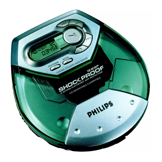
Portable compact disc player
TABLE OF CONTENTS
Technical specification ......................................................1-1
Connections and controls ..................................................1-2
Features ............................................................................1-3
Accessories .......................................................................1-3
Safety & Warnings .............................................................1-4
Repair positions ............................................................2-1
Dismantling CD-door .....................................................2-1
Handling chip components............................................2-2
Service tools..................................................................2-2
Pin description of ICs ................................................3-1...3-3
Start-up procedure.............................................................3-4
Service Test Program................................................3-5...3-6
©
Copyright 2001 Philips Consumer Electronics B.V. Eindhoven, The Netherlands
All rights reserved. No part of this publication may be reproduced, stored in a retrieval
system or transmitted, in any form or by any means, electronic, mechanical, photocopying,
or otherwise without the prior permission of Philips.
Published by YT 0150 Service Audio
AX 2100
AX 2101
AX 2102
AX 5100
AX 5101
Printed in The Netherlands
Subject to modification
AX 5102
AX 5113
AX 5103
AX 5114
AX 5104
AX 5115
AX 5111
AX 5116
AX 5112
AX 5117
Blockdiagram .....................................................................3-7
Circuit diagrams
CD part ..........................................................................4-1
Control / Supply partpart ...............................................4-2
Audio part......................................................................4-3
Componentside view .....................................................4-4
Copperside view............................................................4-5
Exploded view ...................................................................5-1
Mechanical partslist ...........................................................5-1
Electrical partslist ......................................................6-1...6-4
AX 5118
AX 7101
AX 7104
AX 7113
all versions
PRODUCT FAMILY FOCUS ESP
CLASS 1
© 3140 785 22870
Advertisement
Table of Contents

Related Manuals for Philips AX 2100


Summary of Contents for Philips AX 2100
-
Page 1: Table Of Contents
LASER PRODUCT © Copyright 2001 Philips Consumer Electronics B.V. Eindhoven, The Netherlands All rights reserved. No part of this publication may be reproduced, stored in a retrieval system or transmitted, in any form or by any means, electronic, mechanical, photocopying, or otherwise without the prior permission of Philips. -
Page 2: Technical Specification
TECHNICAL SPECIFICATION General Shock resistance Dimensions (WxHxD) : 129x26x140mm +X/-X direction : ≥2.5g Weight without batteries : 220g +Y/-Y direction : ≥2.5g +Z/-Z direction : ≥2.0g Power supply modes Headphone out (measured with 16 Ω load, DBB/ESP off) DC-in socket : 2.5-6.0V Primary batteries (2xLR6) : 1.7-3.6V... -
Page 3: Connections And Controls
$ ......belt clip holder # VOL E ..adjusts the volume % ......typeplate $ 4.5V DC...socket for external power supply % ......belt clip holder ^ ......typeplate For more information of operation instruction please visit Philips Audio internet site : http://www.audio.philips.com... -
Page 4: Features
FEATURES FEATURES OF CD-PORTABLE PRODUCT FAMILY FOCUS ESP CD-RW COMPATIBILITY ELECTRONIC SKIP PROTECTION 100s 100s 100s ESP DRAM SIZE [Mbit] HOLD / RESUME FUNCTION DBB STAGES ACOUSTIC FEEDBACK PROGRAM MEMORY RECHARGE NiCd / NiMH --/-- --/-- --/-- --/-- --/-- --/-- --/-- --/-- --/--... -
Page 5: Safety & Warnings
SAFETY & WARNINGS © ñ WARNING WAARSCHUWING All ICs and many other semiconductors are susceptible to Alle IC´s en vele andere halfgeleiders zijn gevoelig voor electrostatic discharges (ESD). Careless handling during electrostatische ontladingen (ESD). repair can reduce life drastically. Onzorgvuldig behandelen tijdens reparatie kan de levensduur When repairing, make sure that you are connected with the drastisch doen vermindern. -
Page 6: Service Hints
SERVICE HINTS REPAIR POSITION COPPERSIDE REPAIR POSITION COMPONENTSIDE To get access to the copperside of the To get access to the componentside of the printed board assembly proceed as follows: printed board assembly proceed as follows: 1. Remove the bottom screws (6x) 1. -
Page 7: Handling Chip Components
HANDLING CHIP COMPONENTS SERVICE TOOLS Audio signal disc SBC429 4822 397 30184 Playability test disc SBC444 4822 397 30245 Test disc 5 (disc without errors) + Test disc 5A (disc with dropout errors, black spots and fingerprints) SBC426/SBC426A 4822 397 30096 ESD PROTECTION EQUIPMENT Anti-static table mat large 1200x650x1.25mm 4822 466 10953... - Page 8 PIN DESCRIPTION OF INTEGRATED CIRCUITS TZA1024 – HF-PREAMPLIFIER AND LASER SUPPLY CIRCUIT Name Direction Description ––––––––––––––––––––––––––––––––––––––––––––––––––––––––––––––––––––––––––––––––––––––––––––––––––––––––––– HF-preamp → CD-drive current output to laser diode VCCL +2.6V laser supply voltage → HF-preamp CFIL external filter capacitor CD-drive → HF-preamp laser monitor diode input CD-drive →...
- Page 9 SAA7324 – DECODER, DIGITAL SERVO IC AND D/A-CONVERTER CD10 (low voltage version) Name Direction Description ––––––––––––––––––––––––––––––––––––––––––––––––––––––––––––––––––––––––––––––––––––––––––––––––––––––––––– → CD10 HFREF comparator common mode input → CD10 HFIN comparator signal input CD10 → ISLICE current feedback from data slicer VSSA1 analog ground 1 VDDA1 +2.6V analog supply voltage 1...
- Page 10 SM5907AF – COMPRESSION-TYPE ANTI-SHOCK MEMORY CONTROLLER NPC Name Direction Description ––––––––––––––––––––––––––––––––––––––––––––––––––––––––––––––––––––––––––––––––––––––––––––––––––––––––––– VDD2 +2.6V supply voltage NPC ↔ µP interface extension I/O line 1 NPC ↔ µP interface extension I/O line 2 NPC ↔ µP interface extension I/O line 3 NPC ↔ µP interface extension I/O line 4 NPC ↔...
-
Page 11: Start-Up Procedure
START-UP PROCEDURE – FLOW CHART START-UP PROCEDURE - FLOW CHART Start-up procedure for ext.DC supply, POWER OFF no accu inserted, hold-switch in off pos., (stand-by) ESP on, resume-mode off, CD-door closed. focus found PLAY during ramping pressed ? cycle ? µP sends new focus parameters to CD10 (switch to higher... -
Page 12: Service Test Program
SERVICE TEST PROGRAM 1. PRELIMINARY SETUP 6. FOCUS TEST • To enter the service test program disconnect the AC/DC adaptor Purpose: Check movement of lens and operation of focus servo for and remove batteries, open the CD-door and hold the buttons CDDA and CDRW discs. - Page 13 SERVICE TEST PROGRAM – FLOW CHART To enter the service test program PRELIMINARY 1. Disconnect the AC/DC adaptor and remove batteries SETUP 2. Open the CD-door 3. Hold “PLAY” & “PREV” buttons depressed CD TEST 4. Connect the AC/DC adaptor or insert batteries Display shows “PLAY”...
-
Page 14: Blockdiagram
BLOCKDIAGRAM Keyboard Only for AX71xx - ESP100 (Membrane) From / To +2.6V RC - socket +2.6V +2.6V 16MBit Circuit TMP86CH21 DRAM TZA1024 Laser Power Control LCD Driver HF Amplifier +2.6V DA23 (LN) D1-4, R1-2 CD-Drive 16MBit From/To DRAM From/To +2.6V Supply &... -
Page 15: Cd Part
CIRCUIT DIAGRAM - CD PART 1830 B1 2803 C4 2832 E3 2837 E4 2842 E5 2847 B5 2852 A9 2857 F5 2862 B9 2886 D13 2891 C4 3802 B2 3807 C5 3832 C2 3837 D3 3842 D4 3847 C4 3852 A7 3857 A10 3862 C10 3868 F6... - Page 16 CIRCUIT DIAGRAM - CONTROL/SUPPLY PART 1250 H4 1402 B15 2254 B6 2259 D7 2264 E7 2269 G4 2277 E8 2402 E10 2701 I14 3252 C6 3257 D6 3266 E4 3279 H2 3284 E1 3290 G8 3295 D6 3402 B14 3407 E10 3412 D15 3421 B14 3703 I15...
-
Page 17: Audio Part
CIRCUIT DIAGRAM - AUDIO PART 1300 B10 2306 D1 2320 D7 2333 E3 2343 E8 3312 C1 3318 C2 3328 D5 3340 D7 3346 D9 3361 C6 3368 E2 3375 B5 3381 D8 6302 C8 7302 C7 7309 B9 F302 D10 F309 C4 2301 A2 2313 C5... -
Page 18: Pcb Layout Diagram
PCB LAYOUT DIAGRAM - COMPONENT SIDE 1250 F3 2887 D2 4210 D2 1251 C6 2892 E2 5250 B6 1252 C6 2893 D2 5251 A5 1300 F1 2894 E1 6252 C6 1401 B2 3202 E4 6257 C5 1402 D1 3252 E4 6300 E1 1830 C2 3257 E4 6301 G3... - Page 19 PCB LAYOUT DIAGRAM - COPPER SIDE 1400 A3 2841 C5 3286 D2 3410 C2 3850 C5 7430 B4 1840 C4 2842 C5 3288 B2 3411 C3 3851 C5 7700 D3 2250 C1 2844 C5 3289 E3 3412 C3 3852 D5 7701 D3 2251 C1 2845 C5 3290 E3 3413 C3...
-
Page 20: Exploded View
EXPLODED VIEW EXPLODED VIEW DESIGN "P" DESIGN "Q" 10 x SCREW B-1.4x3.5-NI MECHANICAL PARTSLIST SEE TABLE CD-DOOR-ASSY TYPE NO. COLOUR 3103 304 70320 DOOR-BATTERY-2 DOOR-CD ASSY CABINET ASSY PANEL ASSY 3103 307 99610 CABINET - ASSY - 1 AX2100 Translucent 3103 307 99710 CABINET - ASSY - 2 3140 117 62110... -
Page 21: Electrical Partslist
ELECTRICAL PARTSLIST - MISCELLANEOUS - - CAPACITORS - 1003 3140 110 51310 LCD PANEL (AX21../AX51..) 2316 4822 126 14491 2.2µF 20% 10V 1003 3103 308 84250 LCD PANEL (AX71..) 2319 2222 867 15339 33pF 5% NP0 50V 1250 2422 025 12272 CONN. - Page 22 ELECTRICAL PARTSLIST - CAPACITORS - - RESISTORS - 2849 5322 126 11583 10nF 10% X7R 50V 3284 2322 615 13103 NTC 10K 5% 0,21W 2850 5322 126 11579 3,3nF10% X7R 63V 3286 4822 051 30103 10K 5% 0,062W 2851 5322 126 11579 3,3nF10% X7R 63V 3288 4822 051 30109...
- Page 23 ELECTRICAL PARTSLIST - RESISTORS - - RESISTORS - 3372 4822 051 30103 10K 5% 0,062W 3809 4822 051 30563 56K 5% 0,062W 3373 4822 117 13632 100K 1% 0,062W 3830 4822 051 30109 10R 5% 0,062W 3374 4822 117 13632 100K 1% 0,062W 3831 4822 051 30562...
- Page 24 ELECTRICAL PARTSLIST - RESISTORS - - IC & TRANSISTORS - 3885 4822 051 30103 10K 5% 0,062W 7250 9322 003 64676 TBC337-40 3886 4822 051 30103 10K 5% 0,062W 7251 5322 130 44647 BC368 3887 4822 117 12139 22R 5% 0,062W 7252 5322 130 44593 BC369...