Viessmann VITODENS 200 Installation Instructions Manual
Hide thumbs
Also See for VITODENS 200:
- Technical manual (180 pages) ,
- Installation instructions manual (148 pages) ,
- Service manual (132 pages)

Related Manuals for Viessmann VITODENS 200


Summary of Contents for Viessmann VITODENS 200
-
Page 1: Installation Instructions
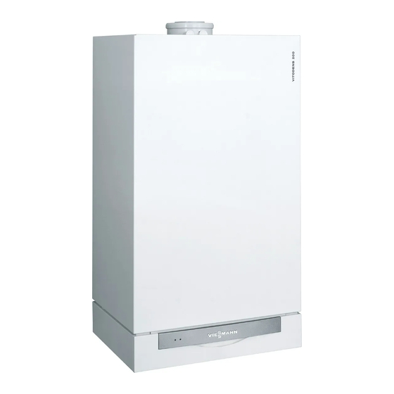
VIESMANN Installation instructions for contractors Vitodens 200 Type WB2A, 8.8 to 26.0 kW Wall mounted gas fired condensing boiler Natural gas and LPG version VITODENS 200 Dispose after installation. 5862 559 GB 10/2006... -
Page 2: Safety Instructions
Safety instructions Please follow these safety instructions closely to prevent accidents and material losses. Safety instructions explained Regulations Danger Observe the following when working This symbol warns against the on this system risk of injury. & all legal instructions regarding the prevention of accidents, Please note &... -
Page 3: Table Of Contents
Index Preparing for installation Product information ..................Preparing for installation ................& Preparing the boiler installation ..............Installation sequence Installing the boiler and making all connections ........... Flue connection ..................Condensate connection ................Gas connection ..................Opening the control unit enclosure .............. 10 Electrical connections ................. -
Page 4: Product Information
Conversion for other target countries The Vitodens 200 should generally only be delivered to those countries speci- fied on the type plate. For deliveries to alternative countries, an approved con- tractor must arrange, on his own initiative, for an individual approval in... -
Page 5: Preparing For Installation
Preparing for installation Preparing the boiler installation For on-site preparation of gas, water and electrical connections, see installation instructions, installation aid or mounting frame. A Heating flow Rp ¾" D Cold water Rp ½" (gas fired combi B DHW Rp ½" (gas fired combi boil- boiler) Cylinder return G ¾"... - Page 6 Preparing for installation (cont.) G Cable entry H Dimension with DHW cylinder below. K Condensate drain Note 2. Prepare the gas connection This boiler (protection level: IP X4 D) according to TRGI or TRF or all is approved for installation in wet local regulations.
-
Page 7: Installing The Boiler And Making All Connections
Installing the boiler and making all connections Note Quick-acting air vent valve and con- nector for the expansion vessel packed separately. A Heating flow B DHW (gas fired combi boiler) Cylinder flow (gas fired boiler) -
Page 8: Flue Connection
Installing the boiler and making all connections (cont.) C Gas connection E Heating return D Cold water (gas fired combi boiler) F Fill & drain valve Cylinder return (gas fired boiler) Flue connection Connect the balanced flue pipe. Flue gas system installation instructions. -
Page 9: Gas Connection
Gas connection 1. Carry out a gas soundness test. Please note Excessive test pressure may damage the boiler and the gas valve. Max. test pressure 150mbar. Where higher pressure is required for leak tests, sepa- rate the boiler and the gas valves from the mains gas A Gas connection supply pipe (undo the fit-... -
Page 10: Opening The Control Unit Enclosure
Opening the control unit enclosure... -
Page 11: Electrical Connections
Electrical connections Information regarding the connection of accessories For details of accessories, also observe their separate installation instructions. Please note Electronic modules can be damaged by electro-static discharges. Touch earthed objects, such as heating or water pipes, to discharge sta- tic loads. - Page 12 Electrical connections (cont.) B Vitotrol 100 UTD (only for con- stant temperature control units) Remove jumper when making this connection. C Vitotrol 100 UTA (only for constant temperature control units) Remove jumper when making this connection. 230 V~ plugs Low voltage plugs fÖ...
-
Page 13: Routing Connecting Cables
Electrical connections (cont.) Routing connecting cables Please note Connecting cables will be damaged if they contact hot parts. When routing and securing connecting cables on site, ensure that the maximum permissible temperatures for these cables are not exceeded. A Low voltage connections F Cable grommet for power supply B 230 V connections cable... -
Page 14: Closing The Control Unit Enclosure And Inserting The Programming Unit
Closing the control unit enclosure and inserting the programming unit... -
Page 15: Front Panel Installation
Front panel installation Commissioning and adjustment For commissioning and adjust- ment, see service instructions. - Page 16 Viessmann Werke GmbH&Co KG Viessmann Limited D-35107 Allendorf Hortonwood 30, Telford Telephone: +49 6452 70-0 Shropshire, TF1 7YP, GB Fax: +49 6452 70-2780 Telephone: +44 1952 675000 www.viessmann.com Fax: +44 1952 675040 E-mail: info-uk@viessmann.com...