Table of Contents
Advertisement
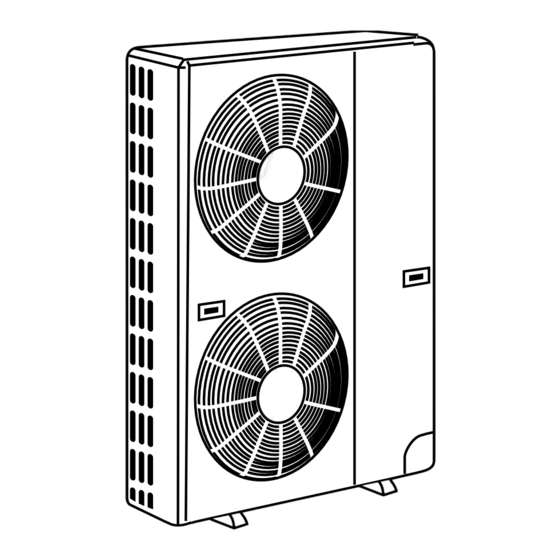
SPLIT-TYPE, AIR CONDITIONERS
TECHNICAL & SERVICE MANUAL
<Outdoor unit>
Models
PU12EK
PU18EK PU18EK
PU24EK PU24EK
PU30EK PU30EK
PU36EK PU36EK
PU42EK2 PU42EK2
PU42EK7 PU42EK7
Outdoor unit
Revision:
•Wiring diagram for PU12EK has been modified in
•Transformer and outdoor controller board for
PU12EK has been modified in "13. PARTS LIST".
Note:
•Refer to other manual as for Indoor Units.
•Please void OC247 REVISED EDITION-D.
1
PU24EK
1
PU30EK
1
PU36EK
1
1
PU42EK7
1
CONTENTS
1. FEATURES ························································2
2. TECHNICAL CHANGE ······································3
3. COMBINATION OF INDOOR AND OUTDOOR UNITS ··············4
4. PART NAMES AND FUNCTIONS·····················4
5. SPECIFICATIONS ·············································5
6. DATA··································································6
7. OUTLINES AND DIMENSIONS ························9
Model name
indication
8. WIRING DIAGRAM··········································13
9. REFRIGERANT SYSTEM DIAGRAM ···················18
10. MICROPROCESSOR CONTROL····················19
11. TROUBLESHOOTING ·····································21
12. DISASSEMBLY INSTRUCTIONS····················25
13. PARTS LIST·····················································29
C
REVISED EDITION-E
PU24EK
2
PU30EK
2
PU36EK
2
2
US
No. OC247
3
3
3
TM
Advertisement
Table of Contents
Troubleshooting

Related Manuals for Mitsubishi PU12EK


Summary of Contents for Mitsubishi PU12EK
- Page 1 8. WIRING DIAGRAM··········································13 9. REFRIGERANT SYSTEM DIAGRAM ···················18 10. MICROPROCESSOR CONTROL····················19 Revision: 11. TROUBLESHOOTING ·····································21 •Wiring diagram for PU12EK has been modified in 12. DISASSEMBLY INSTRUCTIONS····················25 ”8. WIRING DIAGRAM”. 13. PARTS LIST·····················································29 •Transformer and outdoor controller board for PU12EK has been modified in ”13. PARTS LIST”.
- Page 2 Revise point Model Incorrect Correct FUNCTIONAL PARTS T7W 588 425 T7W E07 425 No.12 CAPILLARY TUBE FUNCTIONAL PARTS PU12EK T7W 850 799 T7W A30 799 No.17 TRANSFORMER FUNCTIONAL PARTS T7W 850 315 T7W E08 315 No.20 OUTDOOR CONTROLLER BOARD PU42EK7...
-
Page 3: Wiring Diagram
TECHNICAL CHANGE (OC247 REVISED EDITION-A) Change of the service parts. Refer to “13. PARTS LIST” for the details. PU18EK PU18EK PU24EK PU24EK PU30EK PU30EK PU36EK PU36EK PU42EK2 PU42EK2 1. OUTDOOR CONTROLLER BOARD has been changed. 2. TRANSFORMER has been changed. PU18EK PU18EK •... -
Page 4: Combination Of Indoor And Outdoor Units
— — — — — PC • GK PART NAMES AND FUNCTIONS Air outlet Air outlet Air intake Air intake PU12EK PU18EK PU18EK Outdoor unit Outdoor unit Air outlet Air outlet Air intake Air intake PU24EK PU30EK PU36EK PU42EK2 PU42EK7... -
Page 5: Specifications ·············································5
SPECIFICATIONS MODELS : PU12EK PU18EK PU24EK PU30EK PU36EK PU42EK2 PU42EK7 PU18EK PU24EK PU30EK PU36EK PU42EK2 PU42EK7 PU24EK PU30EK PU36EK PU42EK7 PU24EK PU30EK PU36EK Model PU24EK PU30EK PU36EK PU12EK PU18EK PU42EK2 PU42EK7 Item PU42EK7 PU18EK PU24EK PU24EK PU30EK PU30EK PU36EK PU36EK... -
Page 6: Data··································································6
1. ADDITIONAL REFRIGERANT CHARGE (R22 : oz) Piping length (one way) Factory Service Ref. charged 100 ft 115 ft 130 ft 145 ft 160 ft 164 ft PU12EK — — — 4 lbs 14 oz PU18EK — — — 5 lbs 8 oz PU18EK... -
Page 7: Table Of Contents
3. NOISE CRITERION CURVES PU18EK PU12EK SPL(dB) LINE SPL(dB) LINE PU18EK NC-70 NC-70 NC-60 NC-60 NC-50 NC-50 NC-40 NC-40 NC-30 NC-30 APPROXIMATE APPROXIMATE THRESHOLD OF THRESHOLD OF HEARING FOR HEARING FOR NC-20 NC-20 CONTINUOUS CONTINUOUS NOISE NOISE 1000 2000 4000... -
Page 8: Table Of Contents
PU42EK2 PU42EK7 PU42EK2 PU42EK7 SPL(dB) LINE PU42EK7 MICROPHONE UNIT 3.3ft 3.3ft NC-70 NC-60 GROUND NC-50 NC-40 NC-30 APPROXIMATE THRESHOLD OF HEARING FOR NC-20 CONTINUOUS NOISE 1000 2000 4000 8000 BAND CENTER FREQUENCIES, Hz... -
Page 9: Outlines And Dimensions
OUTLINES AND DIMENSIONS Outdoor Unit PU12EK Unit : inch... - Page 10 Outdoor Unit PU18EK Unit : inch PU18EK...
- Page 11 Unit : inch Outdoor Unit PU24EK PU30EK PU24EK PU30EK PU24EK PU30EK PU24EK PU30EK...
- Page 12 Unit : inch Outdoor Unit PU36EK PU42EK2 PU42EK7 PU36EK PU42EK2 PU42EK7 PU36EK PU42EK7 PU36EK...
- Page 13 WIRING DIAGRAM MODEL : PU12EK PU18EK SYMBOL NAME SYMBOL NAME SYMBOL NAME COMPRESSOR CAPACITOR LD1 ~ LD8 LED <CHECK, SERVICE> OUTDOOR COIL THERMISTOR FAN CAPACITOR COMPRESSOR X11 <O. B> CRANKCASE HEATER RELAY CRANKCASE HEATER OUTDOOR FAN MOTOR (INNER THERMOSTAT) X12 <O. B>...
- Page 14 MODELS : PU18EK SYMBOL NAME SYMBOL NAME SYMBOL NAME COMPRESSOR CAPACITOR LD1 ~ LD8 LED <CHECK, SERVICE> OUTDOOR COIL THERMISTOR FAN CAPACITOR COMPRESSOR X11 <O. B> CRANKCASE HEATER RELAY CRANKCASE HEATER OUTDOOR FAN MOTOR (INNER THERMOSTAT) X12 <O. B> COMPRESSOR RELAY O.
- Page 15 MODELS : PU24EK PU30EK PU36EK PU42EK2 SYMBOL NAME SYMBOL NAME SYMBOL NAME COMPRESSOR CAPACITOR LD1~LD8 LED <CHECK, SERVICE> OUTDOOR COIL THERMISTOR C3, 4 FAN CAPACITOR COMPRESSOR (INNER THERMOSTAT) X11 <O. B> CRANKCASE HEATER RELAY CRANKCASE HEATER MF3, 4 OUTDOOR FAN MOTOR (INNER THERMOSTAT) X12 <O.
-
Page 16: Pu42Ek7 2
MODELS : PU24EK PU30EK PU36EK PU42EK2 PU42EK7 PU24EK PU30EK PU36EK PU24EK PU30EK PU36EK SYMBOL NAME SYMBOL NAME SYMBOL NAME COMPRESSOR CAPACITOR LD1~LD8 LED <CHECK, SERVICE> OUTDOOR COIL THERMISTOR C3, 4 FAN CAPACITOR COMPRESSOR (INNER THERMOSTAT) X11 <O. B> CRANKCASE HEATER RELAY CRANKCASE HEATER MF1, 2 OUTDOOR FAN MOTOR (INNER THERMOSTAT) - Page 17 MODEL : PU42EK7 PU42EK7 SYMBOL NAME SYMBOL NAME SYMBOL NAME CONNECTOR THERMISTOR FOR PIPE TEMPERATURE CN3<O.B> LD1~LD8 LED(CHECK, SERVICE) (CONNECTING WIRES INDOOR/OUTDOOR) (32°F/15kΩ,77°F/5.4kΩ) CN4T<O.B> COMPRESSOR MOTOR (INNER THERMOSTAT) AUXILIARY RELAY FOR CH CONNECTOR(TRANSFORMER) X11<O.B> AUXILIARY RELAY FOR MC CRANKCASE HEATER MF1, 2 FAN MOTOR (INNER THERMOSTAT) X12<O.B>...
-
Page 18: Refrigerant System Diagram
Accumulator Capillary tube Compressor Flared connection Capillary tube size (O.D. I.D. Length) Ball valve Refrigerant pipe (with service port) For PU12EK ({0.126 {0.071 31.5) (Option) For PU18EK, PU18EK ({0.126 {0.063 31.5) 2 sets For PU24EK, PU24EK , PU24EK , PU24EK ({0.126 {0.063 17.3) -
Page 19: Microprocessor Control
MICROPROCESSOR CONTROL OUTDOOR MICROPROCESSOR CONTROL 1. Protection function (1) As soon as a reversed phase, an open phase, or a P. C. board trouble is sensed, the operation stops and the check code is displayed by LED on the outdoor controller board. (2) When a protection function such as high pressure switch and overcurrent relay works for the first time, the operation stops and restarts after 3-minute time delay mode. - Page 20 6. Fixed fan-output While the compressor is operating and the fan output step is indicated by LED, pushing SW2 fixes the fan output of that time. The fixed fan-output can be released when either of the following conditions is satisfied. 1 SW2 is pushed again.
-
Page 21: Troubleshooting
TROUBLESHOOTING 1. SERVICE DATA INDICATION BY SWITCHES ON OUTDOOR CONTROLLER BOARD Setting dip switches SW2 and SW3 on the outdoor controller board enables LED to show the output state and check code. Output state is shown by LED lighting, and check code by blinking. SW1 : Turning SW1 ON clears the check code. - Page 22 1-2 Fan output step To obtain data on the fan output step, add the number of bits of lighting LEDs, and see the graph below to find the fan rotational frequency. 1 PU12EK PU24EK PU30EK 2 PU18EK PU36EK PU42EK2 PU42EK7 PU24EK...
- Page 23 2. TROUBLESHOOTING ACCORDING TO CHECK CODE Blinking Diagnosis of malfunction Cause Check point Reversed phase This model does not have this No need to be checked. function. Open phase This model does not have this No need to be checked. function.
- Page 24 Disconnect between 1 and 1 or 2 and Operation stops. 9 minutes later, the check code ¨P8¨ appears on the remote con- troller display. 5. HOW TO CHECK THE PARTS PU12EK PU18EK PU24EK PU30EK PU36EK PU42EK2...
-
Page 25: Disassembly Instructions
DISASSEMBLY INSTRUCTIONS NOTE : All panels are clasped, and should be Outdoor unit (PU18EK) removed by shifting up and down. OPERATING PROCEDURE PHOTOS 1. Electrical parts Photo 1 (1) Remove top panel (3 screws in front, 2 screws in rear) Screws Top panel (2) Remove cover panel (1 screw). - Page 26 OPERATING PROCEDURE PHOTOS 3. Heat Exchanger, Compressor Photo 4 (1) Remove the rear panel (2 screws in front, 1 screw on the Screws side, 3 screws in the rear). Remove the valve bed, and open the rear panel to the rear to remove. (2) Remove right side panel (4 screws).
- Page 27 NOTE : All panels are clasped, and should be Outdoor unit (PU24EK) removed by shifting up and down. OPERATING PROCEDURE PHOTOS 1. Electrical parts Screws Photo 1 (1) Remove top panel (3 screws in front, 2 screws in rear) (2) Remove cover panel (1 screw). The panel is anchored by clicks to the side panel.
- Page 28 OPERATING PROCEDURE PHOTOS 3. Heat Exchanger, Compressor (1) Remove the rear / right side panel (2 screws in front, 1 screw Screws on the side, 3 screws in the rear). Photo 4 Remove the electrical box, valve bed, and open to the rear to remove (anchors attached).
- Page 29 PARTS LIST STRUCTURAL PARTS PU12EK PU18EK PU18EK Q'ty / set Wiring Remarks Parts No. Parts Name Specifications Diagram (Drawing No.) Symbol 12EK 18EK 18EK R01 A08 662 SIDE PANEL SIDE PANEL R01 A08 668 FRONT PANEL FRONT PANEL FAN GUARD...
- Page 30 STRUCTURAL PARTS PU24EK PU30EK PU24EK PU30EK PU24EK PU30EK PU24EK PU30EK Q'ty / set Wiring Remarks PU24EK PU30EK Parts No. Parts Name Specifications Diagram PU24EK (Drawing No.) PU24EK PU30EK Symbol PU30EK PU24EK PU30EK R01 A11 662 SIDE PANEL (LEFT) R01 A00 675 FAN GUARD R01 A00 655 PANEL HANDLE...
- Page 31 STRUCTURAL PARTS PU36EK PU42EK2 PU42EK7 PU36EK PU42EK2 PU42EK7 PU36EK PU42EK7 PU36EK Q'ty / set Wiring Remarks Parts No. Parts Name Specifications Diagram (Drawing No.) 36EK 42EK2 42EK7 Symbol 36EK 36EK 42EK7 42EK2 42EK7 36EK R01 A14 662 SIDE PANEL (LEFT) R01 A14 668 FRONT PANEL R01 A00 675...
- Page 32 FUNCTIONAL PARTS PU12EK PU18EK PU18EK 1 2 3 4 5...
- Page 33 Q'ty / set Wiring Remarks Parts No. Parts Name Specifications Diagram (Drawing No.) Symbol 12EK 18EK 18EK T7W 850 763 FAN MOTOR S6V-85FPH MF3,MF R01 A00 115 PROPELLER T7W 850 208 HIGH PRESSURE SWITCH OPEN psiG 469 63H2 T7W 966 238 OVERCURRENT RELAY MRA-98880-9030 T7W 969 238...
- Page 34 FUNCTIONAL PARTS PU24EK PU24EK PU24EK PU24EK...
- Page 35 Q'ty / set Wiring Remarks Diagram Parts No. Parts Name Specifications (Drawing No.) 24EK Symbol 24EK 24EK 24EK S6V-60FPN MF3,4,1,2 T7W 851 763 FAN MOTOR R01 A00 115 PROPELLER OPEN psiG 363 63H2 T7W 850 208 HIGH PRESSURE SWITCH R01 41L 413 CHARGE PLUG NH33NBD T97 517 300...
- Page 36 FUNCTIONAL PARTS PU30EK PU30EK PU30EK PU30EK...
- Page 37 Q'ty / set Wiring Remarks Diagram Parts No. Parts Name Specifications (Drawing No.) 30EK Symbol 30EK 30EK 30EK S6V-60FPN MF3,4,1,2 T7W 851 763 FAN MOTOR R01 A00 115 PROPELLER OPEN psiG 363 63H2 T7W 850 208 HIGH PRESSURE SWITCH R01 41L 413 CHARGE PLUG NH41NAD T97 511 300...
- Page 38 FUNCTIONAL PARTS PU36EK PU36EK PU36EK PU36EK...
- Page 39 Q'ty / set Wiring Remarks Diagram Parts No. Parts Name Specifications 36EK (Drawing No.) 36EK 36EK 36EK Symbol T7W 852 763 FAN MOTOR VC086DC MF3,4,1,2 R01 A00 115 PROPELLER T7W 850 208 HIGH PRESSURE SWITCH OPEN psiG 469 63H2 R01 41L 413 CHARGE PLUG T97 518 300 COMPRESSOR...
- Page 40 FUNCTIONAL PARTS PU42EK2 PU42EK2...
- Page 41 Q'ty / set Wiring Remarks Diagram Parts No. Parts Name Specifications (Drawing No.) Symbol 42EK2 42EK2 T7W 853 763 FAN MOTOR PA6N100UG MF3,4,1,2 R01 A00 115 PROPELLER T7W 850 208 HIGH PRESSURE SWITCH OPEN psiG 469 63H2 R01 41L 413 CHARGE PLUG T97 513 300 COMPRESSOR...
- Page 42 FUNCTIONAL PARTS PU42EK7 PU42EK7 PU42EK7...
- Page 43 Q'ty / set Wiring Remarks Parts No. Parts Name Specifications Diagram (Drawing No.) 42EK7 Symbol 42EK7 42EK7 T7W 853 763 FAN MOTOR MF1, 2 PA6N100UG R01 A00 115 PROPELLER T7W 850 208 63H2 HIGH PRESSURE SWITCH OPEN psiG 469 R01 86H 201 DISCHARGE THERMAL SWITCH R01 41L 413 CHARGE PLUG...
- Page 44 2001 MITSUBISHI ELECTRIC ENGINEERING CO., LTD. Distributed in Aug. 2004 No.OC247 REVISED EDITION-E PDF 9 Distributed in Aug. 2004 No.OC247 REVISED EDITION-D PDF 9 Distributed in Dec. 2002 No.OC247 REVISED EDITION-C 17 Distributed in Dec. 2002 No.OC247 REVISED EDITION-B 17 Distributed in May.
- Page 45 3400 Lawrenceville Suwanee Road Suwanee, Georgia 30024 ● Toll Free: 800-433-4822 Toll Free Fax: 800-889-9904 ● www.mrslim.com Specifications are subject to change without notice.