
Related Manuals for Rockford Fosgate 300SP


Summary of Contents for Rockford Fosgate 300SP
- Page 1 300SP 400SP 500XP Installation & Operation 2-Channel & 4-Channel Amplifiers Instalación y funcionamiento...
-
Page 2: Table Of Contents
Using Passive Crossovers ... 10 Remote Punch Bass (300SP & 400SP Only) ... . . 11 NOTE: Review each section for more detailed information. -
Page 3: Safety Instructions
Installation Section of this manual. Other information can be located by using the Table of Contents. We, at Rockford Fosgate, have worked very hard to make sure all the information in this manual is current. But, as we are constantly finding new ways to improve our product, this information is subject to change without notice. -
Page 4: Design Features
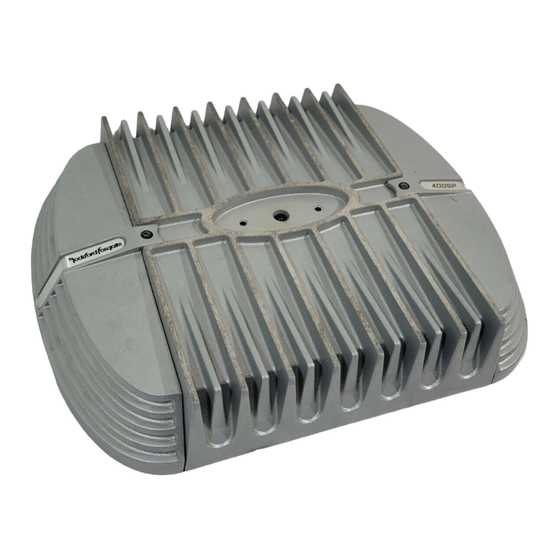
The inherent advantage of casting provides a 30% improvement of cooling over conventional extrusion heatsink designs. 6. Variable Crossover (Models 300SP & 400SP) – Is a built-in 12dB/octave Butterworth filter selectable for High-Pass (HP), All Pass (AP), or Low-Pass (LP) operation variable from 50Hz to 210Hz. -
Page 5: Installation
These inputs should be used if the source unit has only speaker line (high level) outputs and not RCA outputs. 10. Punch Bass (Models 300SP & 400SP) – Helps correct for acoustical deficiencies in the listening environment by helping produce full range sound without adding excessive boost.. The Punch Bass control is a narrow band adjustment at 45Hz variable from 0dB to + 18dB. -
Page 6: Mounting Locations
Stock electrical systems which are in good condition should be able to handle the extra load of any Rockford Fosgate amplifier without problems, although battery and alternator life can be reduced slightly. To maximize the performance of your amplifier, we suggest the use of a heavy duty battery and an energy storage capacitor. - Page 7 Check all power and ground connections for frayed wires and loose connections which could cause problems. NOTE: Follow the diagrams for proper signal polarity. CAUTION: These amplifiers are not recommended for impedance loads below 2Ω stereo and 4Ω bridged (mono). Power Connections - Models 300SP & 400SP...
-
Page 8: 2-Channel Wiring
NSTALLATION Power Connections - Model 500XP Bridged/Mono Wiring – Models 300SP & 400SP (R+) Gray High (R–) Gray/Black Level (L+) White Input (L–) White/Black • RCA OR High Level input connection • Gain - left and right set equally 2-Channel Wiring – Models 300SP & 400SP... - Page 9 NSTALLATION 2-Channel Wiring – Model 500XP • RCA OR High Level Inputs connect to Front • Signal Imput Switch set to 2 • Gain - front and rear set equally • Crossover - front and rear set identically (example; switch to LP and frequency at 60Hz) 3-Channel Wiring –...
-
Page 10: Using Passive Crossovers
NSTALLATION 4-Channel Wiring – Model 500XP • RCA OR High Level Inputs connect to Front and Rear • Signal Imput Switch set to 4 CAUTION: Use only one input configuration. Using both the RCA and High Level inputs will cause undesirable operation. USING PASSIVE CROSSOVERS A passive crossover is a circuit that uses capacitors and/or coils and is placed on speaker leads between the amplifier and speaker. -
Page 11: Remote Punch Bass (300Sp & 400Sp Only)
6.6mF 51mH 3.3mF 100mH 1.6mF REMOTE PUNCH BASS – (Models Mounting 300SP & 400SP Only) Clip Mounting and installation 1. Find a location, either under the dash or near the center console, that gives easy access to the remote. 2. Using the screws supplied, install the mounting clip with the tabs towards t he back. -
Page 12: Operation
Next, turn the amplifier gain setting until once again distortion is audible and then back it down until the distortion is inaudible. Rockford Fosgate source units do not distort, so the volume can be used at maximum setting. -
Page 13: Troubleshooting
ROUBLESHOOTING NOTE: If you are having problems after installation follow the Troubleshooting procedures below. Procedure 1: Check Amplifier for proper connections. Verify that POWER light is on. If POWER light is on skip to Step 2, if not continue. 1. Check in-line fuse on battery positive cable. Replace if necessary. 2. -
Page 14: Specifications
(External to Amplifier) Fuse Type Signal-to-Noise Ratio >100dB A-weighted Crossover Slope 12dB/octave Butterworth Crossover Frequency (Models 300SP & 400SP) variable from 50Hz to 210Hz Crossover Frequency (Model 500XP Fixed 80Hz LP, AP, 120Hz HP Frequency Response 20Hz to 20kHz ±0.5dB Bandwidth 20Hz to 200kHz ±3dB... -
Page 15: Limited Warranty Information
This warranty covers only the original purchaser of Rockford product purchased from an Authorized Rockford Fosgate Dealer in the United States. In order to receive service, the purchaser must provide Rockford with a copy of the receipt stating the customer name, dealer name, product purchased and date of purchase. -
Page 16: International Instructions
¡Insista en ello! Después de todo, su nuevo sistema sólo merece lo mejor. Para darle el toque final a su nueva imagen Rockford Fosgate; pida sus accesorios Rockford, los cuales incluyen playeras, chaquetas, gorras y anteojos para sol. -
Page 17: Instrucciones De Seguridad
INICIO ¡Bienvenidos a Rockford Fosgate! Este manual ha sido creado para proporcionarle información al dueño, vendedor y técnico de instalación. Para quienes desean información rápida sobre cómo instalar este producto, por favor vean la Sección Instalación de este manual. El resto de la información puede encontrarse usando el Índice de Materias. -
Page 18: Características Del Diseño
30% de refrigeración mejorada sobre los diseños convencionales de extrusión para disipación térmica. 6. Transición variable (Modelos 300SP & 400SP) – Es un filtro Butterworth incorporado de 24dB/octava seleccionable para funcionamiento de Paso Alto (HP), Todo Paso (AP), o Paso Bajo (LP) variable, de 50Hz a 210Hz. -
Page 19: Instalación
(alto nivel) del altavoz y no salidas RCA. 5. Bajo Punch (Punch Bass) (Modelos 300SP & 400SP) – Ayuda a corregir las deficiencias acústicas en el entorno auditivo, al ayudar a producir un sonido de gama completa sin añadir una sobrealimentación excesiva. -
Page 20: Lugares De Montaje
PRECAUCIÓN: Si no se siente capaz de instalar el cableado de su nueva unidad, por favor consulte a su Distribuidor Autorizado Rockford Fosgate local sobre la instalación. PRECAUCIÓN: Antes de la instalación, desconecte el terminal negativo de la batería (-) para prevenir daño a la unidad, incendio o posibles lesiones. - Page 21 NOTA: Para establecer la polaridad de señal correcta siga los diagramas. PRECACUCIÓN: No se recomiendan estos amplificadores para cargas de impedancia menores de 2Ω en estéreo y 4Ω con puente (mono). Conexión de corriente - Modelos 300SP y 400SP...
- Page 22 • Ganancia - izquierdo y derecho puestos igualmente Cableado de 2 canales – Modelos 300SP y 400SP • Conexión de entrada RCA o de alto nivel PRECAUCIÓN: Solamente utilice una configuración de entrada. El uso de ambas...
- Page 23 NSTALACIÓN Cableado de 2 canales – Modelo 500XP • Las entradas RCA o de Alto Nivel se conectan al Frente • Interruptor para señal de entrada puesto en 2 • Ganancia - delantero y trasero puestos igualmente • Transición - delanteros y traseros puestos idénticamente (Ejemplo, Izquierdo...
-
Page 24: Uso De X-Overs Pasivos (Transiciones Pasivas)
NSTALACIÓN Cableado de 4 canales – Modelo 500XP • Las entradas RCA o de Alto Nivel se conectan al Frente y Atrás • Interruptor para señal de entrada puesto en 4 PRECAUCIÓN: Solamente utilice una configuración de entrada. El uso de ambas entradas, la RCA y la de Alto Nivel, causa un funcionamiento indeseado. -
Page 25: Bajo Punch Remoto (Punch Bass)
51mH 3.3mF 100mH 1.6mF BAJO PUNCH REMOTO (Punch Bass)– Broche de (Modelos 300SP y 400SP solamente) montaje Montaje e instalación 1. Encuentre un lugar debajo del tablero o cerca del centro de la consola, el cual permita acceder fácilmente al remoto. -
Page 26: Funcionamiento
AJUSTE DE LA FRECUENCIA X-OVER (Transición) Modelos 300SP y 400SP Al colocar el interruptor en la posición HP se pone al amplificador en el modo de Paso Alto, permitiendo el paso de las frecuencias del punto de corte, ajustable entre 50-210Hz. -
Page 27: Solución De Problemas
OLUCIÓN DE ROBLEMAS NOTA: Si tiene problemas después de la instalación, siga los procedimientos de solución de problemas descritos a continuación. Procedimiento 1: Verifique que el amplificador esté bien conectado. Verifique que la luz de ALIMENTACIÓN (POWER) esté encendida. Si la luz de ALIMENTACIÓN está encendida prosiga con el Procedimiento 2. -
Page 28: Especificaciones
SPECIFICACIONES MODELO - PUNCH 300SP 400SP 500XP Clasificación de potencia continua (Valor eficaz) – Medida a 14.4 voltios en la batería 4 Ω-Carga por canal 75 vatios x 2 100 vatios x 2 62,5 vatios x 4 2Ω Carga por canal... -
Page 29: Información Sobre La Garantía Limitada
Qué está cubierto Esta garantía se aplica solamente a los productos Rockford Fosgate vendidos a consumidores por Concesionarios Autorizados Rockford Fosgate en los Estados Unidos o sus posesiones. Los productos comprados por los consumidores en un Distribuidor Autorizado Rockford Fosgate de otro país están cubiertos solamente por el Distribuidor de dicho país y no por Rockford... - Page 30 Español...
- Page 32 Rockford Fosgate Rockford Corporation 546 South Rockford Drive Tempe, Arizona 85281 U.S.A. In U.S.A., (480) 967-3565 In Europe, Fax (49) 8503-934014 In Japan, Fax (81) 559-79-1265 www.rockfordfosgate.com 12/01 B.M. Printed in U.S.A MAN-4010-A...