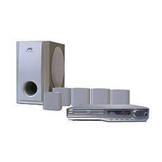
JVC TH-A35 Service Manual
Dvd digital cinema system
Hide thumbs
Also See for TH-A35:
- Instructions manual (68 pages) ,
- Instructions manual (67 pages) ,
- Manuel d'instructions (63 pages)
Table of Contents
Advertisement
Quick Links
SERVICE MANUAL
DVD DIGITAL CINEMA SYSTEM
STANDBY
STANDBY/ON
Contents
Safety Precautions --------------------------- 1- 2
Preventing Static Electricity ----------------- 1- 3
Important For Laser Products ---------------- 1- 4
TH-A35
Description Of Major Ics -------------------- 1- 15
Wiring Connection ---------------------------- 1- 20
COPYRIGHT © 2003 VICTOR COMPANY OF JAPAN, LTD.
COMPACT
D I G I T A L
D I G I T A L ¥ E X
SUPER VIDEO
S U R R O U N D
P R O
L O G I C
VOLUME
PHONES
SOURCE
SORROUND
DSP
Disassembly Method ------------------------ 1- 5
TH-A35
Area Suffix
J ........................ U.S.A.
C ........................ Canada
No. 22020
Jun. 2003
Advertisement
Table of Contents

Summary of Contents for JVC TH-A35
- Page 1 TH-A35 SERVICE MANUAL DVD DIGITAL CINEMA SYSTEM TH-A35 COMPACT D I G I T A L D I G I T A L ¥ E X SUPER VIDEO S U R R O U N D P R O L O G I C...
-
Page 2: Safety Precautions
TH-A35 Safety Precautions 1. This design of this product contains special hardware and many circuits and components specially for safety purposes. For continued protection, no changes should be made to the original design unless authorized in writing by the manufacturer. Replacement parts must be identical to those used in the original circuits. - Page 3 TH-A35 Preventing static electricity Electrostatic discharge (ESD), which occurs when static electricity stored in the body, fabric, etc. is discharged, can destroy the laser diode in the traverse unit (optical pickup). Take care to prevent this when performing repairs. 1.1. Grounding to prevent damage by static electricity Static electricity in the work area can destroy the optical pickup (laser diode) in devices such as DVD players.
- Page 4 TH-A35 Important for laser products 1. CLASS 1 LASER PRODUCT 5. CAUTION : If safety switches malfunction, the laser is able to function. 2. CAUTION : Visible and invisible laser radiation when open and interlock failed or defeated. Avoid direct 6.
- Page 5 TH-A35 Disassembly method Commence disassembly of this set by removing the main units and then proceed to the components and assemblies inside the units. < MAIN BODY > Removing the cabinet top Removing the tray Door Removing the cabinet front Removing the TUNER and panel rear <...
- Page 6 TH-A35 < MAIN BODY > Removing the cabinet top Top cover (See Fig.1) 1. Unscrew the 6 serew A 2. Lift the cabinet top by holding the two sides of it, while moving it upward and backward. Removing the Tray Door (See Fig.2)
- Page 7 TH-A35 Removing the cabinet front (See Fig.3) [Caution] You must ensure the TRAY door isn't it's place before you remove the panel front from body. 1. Unscrew the serew 2 C & 2 D. 2. Pull the panel front toward yourself while pressing 5 stoppers to disengage.
- Page 8 TH-A35 Removing the MAIN Board ( See Fig.6 & 7 ) [Caution] Main board may be taken out when the mpeg board has been taken away. 1. Force the PCB spacer Q to exit the holes of main board. 2. Unscrew the screw P.
- Page 9 TH-A35 Removing the CD mechanism base assembly (See Fig.10) Prior to performing the following procedure, remove the cabinet front assembly. 1. Disconnect the harnesses from connector CN191 and CN192 on the main board and release them from the cord stopper respectively.
- Page 10 TH-A35 <Front panel assembly> Removing the front PWB & Led, PWB (See Fig.12-13) Prior to performing the following procedure, remove the front panel assembly. 1. Remove the seven screws X and 3 screws attaching the front panel board inside the front panel assembly.
- Page 11 TH-A35 Description of major ICs STK402-950 ( U701 ) : 5 channels AF power amplifier. 1. Pin layput ¥~«‹„ˇ 4 200 (unit: m m) 78.0 70.0 (12.0) 23x2.0=46.0 2. Block diagram 1-11...
- Page 12 TH-A35 WM8770 ( U1 ) : 8-channel code c & volume control 2. PIN CONFIGURATION 1-12...
- Page 13 TH-A35 UPD78F0034A ( IC 401 ) : CPU 1.Block Diagram 1-13...
- Page 14 TH-A35 2.Outline of Function 1-14...
- Page 15 TH-A35 Description of major ICs UPD 16315 ( IC904 ): VFD control ler / driver 1. BLOCK DIAGRAM 1-15...
- Page 16 TH-A35 AK4112 ( U17 ) : Digital audio receiver 1. BLOCK DIAGRAM 2. Pin Layout ( AK4112BVF ) 1-16...
- Page 17 TH-A35 M29W160DB ( U12 ) : 16M Flash memory .Pim layout BYTE V SS DQ15A±1 DQ14 DQ13 DQ12 V CC M29W160DT M29W160DB DQ11 DQ10 V SS AI03844 1-17...
- Page 18 TH-A35 2a3020 ( IC 701 ): DC - DC Regulator Internal Regulators Current Sense S l o p e Amp llfler C o m p e n s a t i o n Oscillator SYNC C L K 40 / 400 KHz...
- Page 19 TH-A35 IR2110 ( IC603,604 ): Low and nigh side driver Functional Block Diagram DETECT PULSE LEVEL SHIFT FILTER LEVEL SHIFT PULSE DETECT LEVEL SHIFT DELAY MC 14053B ( U21 ): digitally - controlled analog swith Pin layout 1-19...
- Page 20 TH-A35 Wiring connection 1-20...
- Page 21 TH-A35 < M E M O > 1-21...
- Page 22 TH-A35 VICTOR COMPANY OF JAPAN, LIMITED AV & MULTIMEDIA COMPANY AUDIO/VIDEO SYSTEMS CATEGORY 10-1,1Chome,Ohwatari-machi,Maebashi-city,371-8543,Japan No.22020 Printed in Japan 200305...


