Table of Contents
Advertisement
Service
Manual
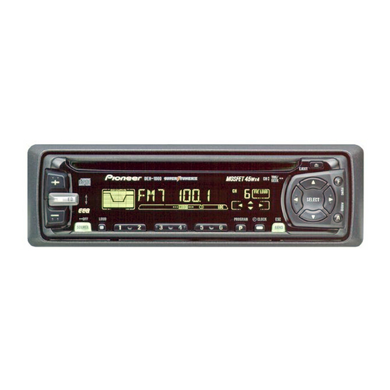
HIGH POWER CD PLAYER WITH FM/AM TUNER
DEH-1000
DEH-10
DEH-1050
- See the separate manual CX-916(CRT2300) for the CD mechanism description, disassembly and circuit
description.
- The CD mechanism employed in this model is one of S8 series.
CONTENTS
1. SAFETY INFORMATION ............................................2
2. EXPLODED VIEWS AND PARTS LIST .......................2
3. SCHEMATIC DIAGRAM ...........................................12
4. PCB CONNECTION DIAGRAM ................................28
5. ELECTRICAL PARTS LIST ........................................38
6. ADJUSTMENT..........................................................44
PIONEER ELECTRONIC CORPORATION
PIONEER ELECTRONICS SERVICE INC.
PIONEER ELECTRONIC [EUROPE] N.V.
PIONEER ELECTRONICS ASIACENTRE PTE.LTD. 253 Alexandra Road, #04-01, Singapore 159936
C PIONEER ELECTRONIC CORPORATION 1998
DEH-1000/X1N/UC
1
X
N/UC
1
X
4-1, Meguro 1-Chome, Meguro-ku, Tokyo 153-8654, Japan
P.O.Box 1760, Long Beach, CA 90801-1760 U.S.A.
Haven 1087 Keetberglaan 1, 9120 Melsele, Belgium
N/ES
7. GENERAL INFORMATION .......................................48
7.1 PARTS .................................................................48
7.1.1 IC................................................................48
7.1.2 DISPLAY ....................................................55
7.2 DIAGNOSIS ........................................................56
7.2.1 DISASSEMBLY .........................................56
7.2.2 TEST MODE ..............................................57
7.3 BLOCK DIAGRAM ..............................................61
8. OPERATIONS AND SPECIFICATIONS.....................62
K-ZZD. DEC. 1998 Printed in Japan
ORDER NO.
CRT2313
1
X
N/UC
Advertisement
Table of Contents

Related Manuals for Pioneer DEH-1000


Summary of Contents for Pioneer DEH-1000
-
Page 1: Table Of Contents
PIONEER ELECTRONICS SERVICE INC. P.O.Box 1760, Long Beach, CA 90801-1760 U.S.A. PIONEER ELECTRONIC [EUROPE] N.V. Haven 1087 Keetberglaan 1, 9120 Melsele, Belgium PIONEER ELECTRONICS ASIACENTRE PTE.LTD. 253 Alexandra Road, #04-01, Singapore 159936 C PIONEER ELECTRONIC CORPORATION 1998 K-ZZD. DEC. 1998 Printed in Japan... -
Page 2: Safety Information
DEH-1000,10,1050 - CD Player Service Precautions 2. During disassembly, be sure to turn the power off 1. For pickup unit(CXX1285) handling, please refer since an internal IC might be destroyed when a con- to"Disassembly"(CX-916 Service Manual CRT2300). nector is plugged or unplugged. - Page 3 13 ••••• 14 Carton See Contrast table(2) 15 Contain Box See Contrast table(2) (2) CONTRAST TABLE DEH-1000/X1N/UC, DEH-10/X1N/UC and DEH-1050/X1N/ES are constructed the same except for the fol- lowing: Part No. Mark No. Symbol and Description DEH-1000/X1N/UC DEH-10/X1N/UC DEH-1050/X1N/ES 12 Polyethylene Bag...
- Page 4 DEH-1000,10,1050 2.2 EXTERIOR - DEH-1000/X1N/UC...
- Page 5 DEH-1000,10,1050 - EXTERIOR SECTION PARTS LIST Mark No. Description Part No. Mark No. Description Part No. 1 Screw BMZ26P120FMC 36 FM/AM Tuner Unit CWE1501 2 Screw BSZ26P060FMC 37 Holder CNC7532 3 Screw BSZ30P060FMC 38 Chassis Unit CXB3167 4 Screw BSZ30P120FMC...
- Page 6 DEH-1000,10,1050 - DEH-10/X1N/UC...
- Page 7 DEH-1000,10,1050 - EXTERIOR SECTION PARTS LIST Mark No. Description Part No. Mark No. Description Part No. 1 Screw BMZ26P120FMC 36 FM/AM Tuner Unit CWE1501 2 Screw BSZ26P060FMC 37 Holder CNC7532 3 Screw BSZ30P060FMC 38 Chassis Unit CXB3167 4 Screw BSZ30P120FMC...
- Page 8 DEH-1000,10,1050 - DEH-1050/X1N/ES...
- Page 9 DEH-1000,10,1050 - EXTERIOR SECTION PARTS LIST Mark No. Description Part No. Mark No. Description Part No. 1 Screw BMZ26P120FMC 36 FM/AM Tuner Unit CWE1501 2 Screw BSZ26P060FMC 37 Holder CNC7532 3 Screw BSZ30P060FMC 38 Chassis Unit CXB3167 4 Screw BSZ30P120FMC...
- Page 10 DEH-1000,10,1050 2.3 CD MECHANISM MODULE...
- Page 11 DEH-1000,10,1050 - CD MECHANISM MODULE SECTION PARTS LIST Mark No. Description Part No. Mark No. Description Part No. 1 Control Unit CWX2344 46 Sheet CNM6215 2 Connector(CN802) CKS2192 47 Ball CNR1189 3 Connector(CN801) CKS2193 48 Belt CNT1086 4 Connector(CN701) CKS2773...
-
Page 12: Schematic Diagram
DEH-1000,10,1050 3. SCHEMATIC DIAGRAM 3.1 OVERALL CONNECTION DIAGRAM(GUIDE PAGE) Note: When ordering service parts, be sure to refer to “EXPLODED VIEWS AND PARTS LIST” or “ELECTRICAL PARTS LIST”. Large size SCH diagram 4.3V 4.3V 4.3V Guide page 4.3V 4.3V 4.3V 4.3V... - Page 13 DEH-1000,10,1050 4.3V 4.3V 4.3V 4.3V OURCE SELECTOR, LECTRONIC VOLUME RESET CEK1136 R612 R613 DEH-P1000/X1N/UC DELETED DEH-P10/X1N/UC DEH-P1050/X1N/ES DELETED...
- Page 14 DEH-1000,10,1050...
- Page 15 DEH-1000,10,1050...
- Page 16 DEH-1000,10,1050...
- Page 17 DEH-1000,10,1050...
- Page 18 DEH-1000,10,1050 3.2 FM/AM TUNER UNIT Voltage of IC Terminals Mark Band Input Level None – – 0dBf 65dBf F125 125dBf 0dBµ 74dBµ A125 125dBµ...
- Page 19 DEH-1000,10,1050...
- Page 20 DEH-1000,10,1050 3.3 KEYBOARD UNIT KEYBOARD UNIT IL1801-1805 DEH-1000/X1N/UC CEL1549 DEH-1050/X1N/ES DEH-10/X1N/UC CEL1508 CLOCK...
- Page 21 DEH-1000,10,1050 CAW1500 PD6294A...
- Page 22 DEH-1000,10,1050 3.4 CD MECHANISM MODULE CONTROL UNIT PICKUP UNIT(SERVICE) PHOTO UNIT...
- Page 23 DEH-1000,10,1050 SWITCHES: CONTROL UNIT S801 : HOME SWITCH..ON-OFF S802 : CLAMP SWITCH..ON-OFF The underlined indicates the switch position.
- Page 24 DEH-1000,10,1050 Note:1. The encircled numbers denote measuring pointes in the circuit diagram. 2. Reference voltage REFO:2.5V - Waveforms 1 RFI 1 CH1: RFI 1 CH1: RFI 0.5V/div. 0.5µs/div. 1V/div. 1V/div. 0.5ms/div. 0.5ms/div. 2 CH2: MIRR 2 CH2: MIRR Normal mode: play 5V/div.
- Page 25 DEH-1000,10,1050 8 CH1: TE 8 CH1: TE 0 MD 0.2V/div. 0.5V/div. 0.5V/div. 0.1s/div. 20ms/div. 5ms/div. 9 CH2: TD ! CH2: SD 0.2V/div. 0.5V/div. Normal mode: play TEST mode: 100 Tracks jump(FWD) Normal mode: Play (12cm) → REFO → REFO →...
- Page 26 DEH-1000,10,1050 ( CH1: R OUT 6 CH1: FE 8 CH1: TE 1V/div. 0.2V/div. 0.2V/div. 0.2ms/div. 1ms/div. 1ms/div. ) CH2: L OUT 9 CH2: TD 3 CH2: FD 1V/div. 0.5V/div. 0.5V/div. Normal mode: Play (1kHz 0dB) Normal mode: During AGC Normal mode: During AGC →...
- Page 27 DEH-1000,10,1050...
-
Page 28: Pcb Connection Diagram
DEH-1000,10,1050 4. PCB CONNECTION DIAGRAM 4.1 TUNER AMP UNIT NOTE FOR PCB DIAGRAMS TUNER AMP UNIT 1. The parts mounted on this PCB include all necessary parts for several destination. For further information for respective destinations, be sure to check with the schematic dia- gram. - Page 29 DEH-1000,10,1050 SIDE A IP BUS IN SUB WOOFER/ REAR PREOUT L ch R ch CN1801...
- Page 30 DEH-1000,10,1050 TUNER AMP UNIT...
- Page 31 DEH-1000,10,1050 SIDE B...
- Page 32 DEH-1000,10,1050 4.2 FM/AM TUNER UNIT SIDE A...
- Page 33 DEH-1000,10,1050 SIDE B...
- Page 34 DEH-1000,10,1050 4.3 KEYBOARD UNIT SIDE A ←...
- Page 35 DEH-1000,10,1050 SIDE B...
- Page 36 DEH-1000,10,1050 4.4 CD MECHANISM MODULE SIDE A...
- Page 37 DEH-1000,10,1050 SIDE B...
-
Page 38: Electrical Parts List
CKS.., CCS.., CSZS..=====Circuit Symbol and No.===Part Name Part No. =====Circuit Symbol and No.===Part Name Part No. ------ ------------------------------------------ ------------------------- ------ ------------------------------------------ ------------------------- Unit Number : CWM6092(DEH-1000/X1N/UC,10/X1N/UC) RD1/4PU222J Unit Name : Tuner Amp Unit RS1/10S222J RS1/10S0R0J MISCELLANEOUS RS1/10S681J RS1/10S473J PML003AM PAL005A... - Page 39 DEH-1000,10,1050 =====Circuit Symbol and No.===Part Name Part No. =====Circuit Symbol and No.===Part Name Part No. ------ ------------------------------------------ ------------------------- ------ ------------------------------------------ ------------------------- RD1/4PU472J CCSQCH101J50 RS1/8S472J CCSQCH101J50 RD1/4PU302J CCSQCH101J50 RS1/10S1R0J CCSQCH101J50 RS1/10S681J CCSQCH101J50 RD1/4PU102J CEJA2R2M50 RS1/10S102J CEJA4R7M35 RD1/4PU102J 470µF/16V CCH1331 RD1/4PU102J CKSQYB473K25...
- Page 40 DEH-1000,10,1050 =====Circuit Symbol and No.===Part Name Part No. =====Circuit Symbol and No.===Part Name Part No. ------ ------------------------------------------ ------------------------- ------ ------------------------------------------ ------------------------- RS1/10S0R0J RD1/4PU102J RS1/8S473J RS1/10S102J RD1/4PU221J RD1/4PU102J RD1/4PU221J RD1/4PU102J RS1/10S0R0J RS1/10S473J RD1/4PU222J RS1/10S103J RS1/10S222J RS1/10S473J RS1/10S0R0J RS1/10S103J RS1/10S681J RS1/10S473J RS1/10S473J...
- Page 41 DEH-1000,10,1050 =====Circuit Symbol and No.===Part Name Part No. =====Circuit Symbol and No.===Part Name Part No. ------ ------------------------------------------ ------------------------- ------ ------------------------------------------ ------------------------- CEJA2R2M50 RS1/16S0R0J CEJA4R7M35 RS1/16S470J 470µF/16V CCH1331 RS1/16S103J CKSQYB473K25 RS1/16S103J CEJA101M10 RS1/16S331J CKSQYB473K25 RS1/16S331J 330µF/16V CCH1326 RS1/16S560J CKSQYB103K50 RS1/16S560J CEJA101M16...
- Page 42 =====Circuit Symbol and No.===Part Name Part No. =====Circuit Symbol and No.===Part Name Part No. ------ ------------------------------------------ ------------------------- ------ ------------------------------------------ ------------------------- CKSQYB224K16 Unit Number : CWM6098(DEH-1000/X1N/UC, CEALNP100M10 DEH-1050/X1N/ES) CCSRCH151J50 Unit Name : Keyboard Unit CKSRYB473K16 CKSRYB682K25 MISCELLANEOUS CEALR68M50 IC 1801 PD6294A...
- Page 43 DEH-1000,10,1050 =====Circuit Symbol and No.===Part Name Part No. =====Circuit Symbol and No.===Part Name Part No. ------ ------------------------------------------ ------------------------- ------ ------------------------------------------ ------------------------- 1807 Switch CSG1110 RS1/16S473J 1808 Switch CSG1110 RA4C681J 1809 Switch CSG1110 RS1/16S102J 1810 Switch CSG1111 RS1/16S102J 1811 Switch CSG1110...
-
Page 44: Adjustment
DEH-1000,10,1050 6. ADJUSTMENT 6.1 CD ADJUSTMENT 1) Precautions 2) Test Mode • This unit uses a single power supply (+5V) for the reg- This mode is used for adjusting the CD mechanism ulator. The signal reference potential, therefore, is module of the device. - Page 45 DEH-1000,10,1050 - Flow Chart Test Mode In Reset Sourse CD SOURCE New test mode BAND Power ON (Adjustment for T.Offset) Power ON RF AMP Gain Select (Not adjustment for T.Offset) 00 00 00 Display 99 99 99 GG GG GG...
-
Page 46: Checking The Grating After Changing The Pickup Unit
DEH-1000,10,1050 6.2 CHECKING THE GRATING AFTER CHANGING THE PICKUP UNIT • Note : The grating angle of the PU unit cannot be adjusted after the PU unit is changed. The PU unit in the CD mecha- nism module is adjusted on the production line to match the CD mechanism module and is thus the best adjusted PU unit for the CD mechanism module. - Page 47 DEH-1000,10,1050 Ech → Xch 20mV/div, AC Grating waveform Fch → Ych 20mV/div, AC 0° 30° 45° 60° 75° 90°...
-
Page 48: General Information
DEH-1000,10,1050 7. GENERAL INFORMATION 7.1 PARTS 7.1.1 IC - Pin Functions (PD4991A) Pin No. Pin Name Function and Operation Not used SYSPW System power supply control output Not used TESTIN Test program mode input 6–9 Not used TUNPW Tuner power control output... - Page 49 DEH-1000,10,1050 Pin No. Pin Name Function and Operation clamp CD disc clamp sense input xsck CD LSI clock output CD LSI data input CD LSI data output CD LSI command/data control output xrst CD LSI reset output xstb CD LSI strobe output...
- Page 50 DEH-1000,10,1050 - Pin Functions (PD6294A) Pin No. Pin Name Function and Operation Crystal oscillator connection pin Crystal oscillator connection pin Not used MOD1,0 Connect to GND Not used KYDT Key data output DPDT Display data input REMIN Remote control pulse input...
- Page 51 DEH-1000,10,1050 PML003AM Rear- Loud- Front- IN1_R IN2_R IN3_R IN4+_R IN4-_R AGND out_R SVin_R out_R out_R FIE_R DATA Isolator circuit Anti radiation Fader Secondary Anti Alias filter volume volume filter Loudness volume Primary Treble Zero cross volume Auto-Zero detect circuit Bass...
- Page 52 DEH-1000,10,1050 - Pin Functions (UPD63710GC) Pin No. Pin Name Function and Operation Logic circuit GND HOLD Defect detection output MIRR MIRR output RFOK signal output Reset signal input Command/parameter identification signal input Data strobe signal input Clock signal input for serial data input/output...
- Page 53 DEH-1000,10,1050 Pin No. Pin Name Function and Operation ATEST Test pin RFMODE Use/not use select for internal RF amplifier A.GND Analog circuit GND Focus drive output Tracking drive output Sled drive output Spindle drive output DACO DAC output for adjustment...
- Page 54 DEH-1000,10,1050 - Pin Functions (BA5985FM) Pin No. Pin Name Function and Operation Loading driver FWD input OPIN1(+) CH1 pre-amplifier input OPIN1(−) CH1 pre-amplifier inverted input OPOUT1 CH1 pre-amplifier output OPIN2(+) CH2 pre-amplifier input OPIN2(−) CH2 pre-amplifier inverted input OPOUT2 CH2 pre-amplifier output Power supply VOL(−)
-
Page 55: Display
DEH-1000,10,1050 7.1.2 DISPLAY - CAW1500... -
Page 56: Diagnosis
DEH-1000,10,1050 7.2 DIAGNOSIS 7.2.1 DISASSEMBLY Removing the Case Unit(not shown) 1. Remove the Case Unit. Removing the Panel Assy(Fig.1) Disengage the stoppers at two locations. Remove the Panel Assy. Removing the CD Mechanism Module (not shown) 1. Remove the four screws. -
Page 57: Test Mode
DEH-1000,10,1050 7.2.2 TEST MODE - Error Messages If a CD is not operative or stopped during operation due to an error, the error mode is turned on and cause(s) of the error is indicated with a corresponding number. This arrangement is intended at reducing nonsense calls from the users and also for facilitating trouble analysis and repair work in servicing. - Page 58 DEH-1000,10,1050 - New Test Mode S-CD plays the same way as before. If an error such as off focus, spindle unlocking, unreadable sub-code, or sound skipping occurs after setup, its cause and time occurred (in absolute time) are displayed. During setup, operational status of the control software (internal RAM: CPOINT) is displayed.
- Page 59 DEH-1000,10,1050 (4) Display of Operational Status (CPOINT) during Setup Status No. Contents Protective action CD+5V ON process in progress. None Servo LSI initialization (1/3) in progress. None Servo LSI CRAM initialization in progress. None Servo LSI initialization (2/3) in progress.
- Page 60 DEH-1000,10,1050 (5) Display Examples 1) During Setup (When status no. = 11) TRK No. MIN. SEC. 11" 2) During Operation (TOC read, TRK search, Play, FF and REV) The same as in the normal mode. 3) When a Protection Error Occurred Switch to the following displays (A) and (B) using the [BAND] switch: (A) Error occurrence timing display in absolute time.
-
Page 61: Block Diagram
DEH-1000,10,1050 7.3 BLOCK DIAGRAM TUNER AMP UNIT FM/AM TUNER UNIT CONTROL UNIT PICKUP UNIT(SERVICE) PHOTO UNIT KEYBOARD UNIT... -
Page 62: Operations And Specifications
DEH-1000,10,1050 8. OPERATIONS AND SPECIFICATIONS 8.1 OPERATIONS Key Finder Head Unit 5/∞/2/3 buttons Disc loading slot EJECT button FUNCTION button +/– button AUDIO button EQ button Buttons 1 – 6 BAND button LOUD button CLOCK button SOURCE button PGM button... - Page 63 DEH-1000,10,1050 Basic Operation To Listen to Music The following explains the initial operations required before you can listen to music. Note: • Loading a disc in this product. 1. Select the desired source (e.g. tuner). Each press changes the Source ...
- Page 64 DEH-1000,10,1050 Basic Operation Basic Operation of Tuner Manual and Seek Tuning • You can select the tuning method by changing the length of time you press the 2/3 button. Manual Tuning (step by step) 0.5 seconds or less Seek Tuning 0.5 seconds or more...
- Page 65 DEH-1000,10,1050 Basic Operation of Built-in CD Player Eject Note: • The CD function can be turned ON/OFF with the disc remaining in this product. • Discs left partially inserted after ejec- tion may incur damage or fall out. Disc Loading Slot The built-in CD player plays one standard 12 cm or 8 cm (single) CD at a time.
- Page 66 DEH-1000,10,1050 Audio Adjustment Selecting the Equalizer Curve You can switch between Equalizer curves. • Move the EQ button up or down to select the desired Equalizer curve. Equalizer curve POWERFUL + = NATURAL + = VOCAL + = CUSTOM + = EQ FLAT...
- Page 67 DEH-1000,10,1050 Audio Adjustment Audio Menu Functions The Audio Menu features the following functions. Balance Adjustment (FADER) This function allows you to select a Fader/Balance setting that provides ideal listening con- ditions in all occupied seats. 1. Press the AUDIO button and select Fader/Balance mode (FADER) in the Audio Menu.
- Page 68 DEH-1000,10,1050 Audio Menu Functions The Audio Menu features the following functions. Balance Adjustment (FADER) This function allows you to select a Fader/Balance setting that provides ideal listening con- ditions in all occupied seats. 1. Press the AUDIO button and select Fader/Balance mode (FADER) in the Audio Menu.
- Page 69 DEH-1000,10,1050 Equalizer Curve Fine Adjustment You can adjust the center frequency of each equalizer curve band (LOW/MID/HIGH) and the Q factor (curve characteristics). Level (dB) Q=2W Q=2N Center frequency Frequency (Hz) 1. Press the AUDIO button for 2 or more seconds to select Equalizer Curve Fine Adjustment.
- Page 70 DEH-1000,10,1050 Audio Adjustment Front Image Enhancer Function (FIE) The F.I.E. (Front Image Enhancer) function is a simple method of enhancing front imaging by cutting mid- and high-range frequency output from the rear speakers, limiting their out- put to low-range frequencies. You can select the frequency you want to cut.
- Page 71 DEH-1000,10,1050...
-
Page 72: Specifications
DEH-1000,10,1050 8.2 SPECIFICATIONS - DEH-1000/X1N/UC, DEH-10/X1N/UC General CD player Power source ..14.4 V DC (10.8 – 15.1 V allowable) System ........Compact disc audio system Grounding system ........Negative type Usable discs ..........Compact disc Max. current consumption ........10.0 A Signal format .... - Page 73 DEH-1000,10,1050 - DEH-1050/X1N/ES General CD player Power source ..14.4 V DC (10.8 – 15.1 V allowable) System ........Compact disc audio system Grounding system ........Negative type Usable discs ..........Compact disc Max. current consumption ........10.0 A Signal format ....Sampling frequency: 44.1 kHz Dimensions Number of quantization bits: 16;...