Table of Contents
Advertisement
Quick Links
Download this manual
See also:
User Manual
Advertisement
Table of Contents

Related Manuals for LG LG-500


Summary of Contents for LG LG-500
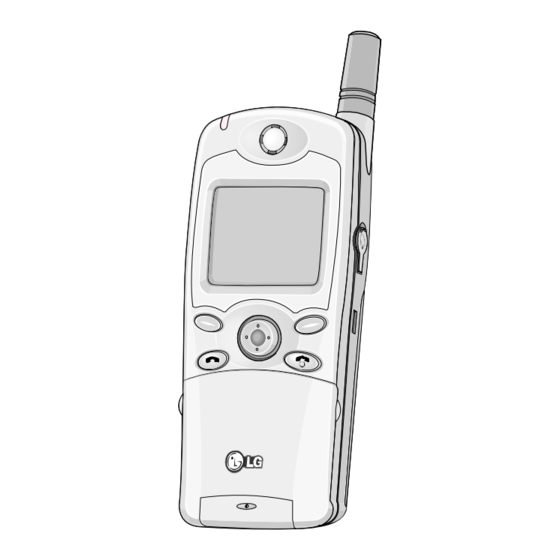
- Page 1 GSM Phone SERVICE MANUAL MODEL : LG-500...
-
Page 2: Table Of Contents
Table Of Contents 5.2.4 Melody Trouble ......28 1. Introduction ........5.2.5 LCD Trouble ......29 2. Specification & Feature ..5.2.6 Charge Trouble ......30 5.2.7 Vibrator is not working ..... 31 2.1 Product Name ........2 5.2.8 Backlight is not Working ..32 2.2 Supporting Standard ...... -
Page 3: Introduction
1. Introduction 1. Introduction LG-500 is a mobile phone operated in the GSM Digital Cellular Mobile Radio System, which is the Pan- European mobile cellular standard. LG-500 has the operation band of GSM 900 and DCS 1800. GSM Phase II features are fully supported and part of the GSM Phase II+ features are also supported. About the SIM Toolkit, LG-500 supports upto Class 3 including Class 1, 2. -
Page 4: Main Features
2. Specification & Feature 2.4 Main Features Category Feature Remark Language English and other languages are under this category. SIM Toolkit Class 1,2,3 Pre-paid SIM Applied Operation Text Input(eZi Text) Language All available languages 2 languages per market Predictive word input Phone Book 1 Phone Numbers for 1 Name 500 Phone numbers... -
Page 5: Hw Features
2.5 HW Features Category Feature Remark Form Factor Flip(Active) Battery 1. Capacity Standard : Li-Ion, 600 mAh Bare Cell : 5.5 x 30 x 48 mm Extended : Li-Ion, 1050 mAh Packed Size: 6.7 x 35 x 50 mm Bare Cell : 8.6 x 34 x 48 mm 2. - Page 6 2. Specification & Feature Category Feature Remark Memory Flash : 4Mbytes SRAM : 512Kbytes EEPROM : 256Kbits Speech coding FR, EFR, HR Data & Fax Built-in Vibrator Built-in Type : Cylinder Melody(for Buzzer Applied/Built-in Buzzer Function by Using Function) Speaker Phone & Melody IC C-Mike Built-in Receiver...
-
Page 7: Sw Features
2.6 SW Features Function Detail Item Specification Display Screen Display Backlight LCD, Keypad RSSI 5 Levels Battery Charging 4 Levels Applied Language Options English and other languages are under this category. Keypad Number of Keys 12 Numeric Keys Send & End Key 4 Navigation Keys 1 Easy Key(O.K) 2 Soft Function Keys... - Page 8 2. Specification & Feature Function Detail Item Specification DTMF DTMF Signalling DTMF Enable & Disable Audio Key Tone Volume 5 Levels Ring Tone Volume 5 Levels Ring Tone Pattern 31 Ring tones Ring Type 1)Ring 2)Vibrate 3)Vibrate & Ring 4)Silent Earpiece Volume 5 Levels Mute &...
- Page 9 Function Detail Item Specification Barring ‘All incoming Calls’ Barring ‘All incoming Calls when roaming’ Plug-In Type Service Provider Lock & Network Lock Auto Detection 3V & 5V Detection SIM Toolkit Class 1, 2, 3 Prepaid SIM Operation Short Message Read Message Write and Edit Message Send and Receive Message Reply to Message...
- Page 10 2. Specification & Feature Function Detail Item Specification Version 1.1 AUR Browser World Time Setting Local Time Number of Selectable Cities 24 Cities Calculator Operator Addition Substraction Multiplication Division Unit Convert Length Conversion Weight Conversion Volume Conversion Surface Conversion PC Sync. Phone Book Sync.
-
Page 11: Keypad Arrangement & Functions
3. Keypad Arrangement & Functions 3.1 Keypad Arrangement 1 Call Indicator Light 10 Star Key 2 Earpiece 11 Active Flip 3 Record Key 12 Antenna 4 Display Screen 13 Handsfree Connector 5 Up/Down Side Key 14 Soft Right Key 6 Soft Left Key 15 Navigation Keys 7 Easy Key 16 END/PWR Key... -
Page 12: Keypad Description
3. Keypad Arrangement & Functions 3.2 Functions of Keys The following shows key components of the phone. Description Soft Left Key / Soft Right Key Each of these keys performs the function indicated by the text on the display immediately above it. WAP Hotkey You can directly connect to WAP by pressing this key. -
Page 13: Disassembly/Reassembly
4. Disassembly/Reassembly Upper Case Lower Case 4.1 Disassembly 4.1.1 Disassembly of Upper Case 1. Push the battery locker, and then remove the battery cover. 2. Pull the battery downward and lift it up. 3. Use your thumb to pull down the battery-locker hard. Battery Cover Figure 4-1. - Page 14 4. Disassembly/Reassembly 4. Loosen the 4 screws as shown below. 5. While the Lower case is detached from the Upper case, twist the Lower case to the right for disassembling a hook. Then twist it again to the left for disassembling the other hook. Finally, take out the Lower case from the Upper case.
- Page 15 4.1.2 Disassembly of Upper-Case Components 1. Release the screws and lift up the speaker holder to remove the speaker. 2. Use a '-' type driver carefully to lift up the Lower case of the vibrator spindle. Assembly: - Make sure the terminal of Speaker is being attached towards the Antenna. - When inserting the earphone cap, place its upper part into the hole first.
- Page 16 4. Disassembly/Reassembly 3. Use a small '-'type driver to insert into the direction and lift it up to remove the battery spring. 4. Also, for the SIM-card cover, use '-'type driver to remove it. 5. Release the Volume BTN by pushing it with opposite force onto each side. And for the Recording BTN, just push one its side to release it.
-
Page 17: Disassembly Of Lower Case
4.1.3 Disassembly of Lower Case 1. Use a '-' type driver to release from the hooks on Lower case. Then, lift up the PCB for final disassembly. 2. Insert a small '-'type driver between the shield-can and cover, and lift up along the flat side of the lower case. -
Page 18: Disassembly Of Lower Case
4. Disassembly/Reassembly 4.1.4 Disassembly of Lower-Case Components 1. Use a pin to lift up the microphone to the direction as shown in fig. 4-7. 2. Use a pin to release the Receiver. Figure 4-7. Removing the Receiver 3. Insert a '-'type driver between the hinge and the Lower case, and lift it up to remove the hinge. 4. -
Page 19: Disassembling Pcb
4.1.5 Disassembly of PCB 1. Lift up the side hooks as shown in fig.4-9. Then the main PCB and the LCD Module will be disassembled. Assembly: - Insert guide-hooks of LCD Module into guide-holes of Main PCB and push it in until it clicks. - When placing Backup-battery onto Battery-hold, make sure the battery poles are facing the right direction. -
Page 20: Assembly
4. Disassembly/Reassembly 4.2 ASSEMBLY - Reassembly of PCB 1. Hang the Main PCB onto the hook on Lower case and push it down. 2. Connect the lead wire of Speaker and Vibrator to the Main PCB. Make sure that the poles are facing right directions. -
Page 21: Data Kit & Test Method
In order to download software of LG-500, the following working environments should be prepared: LG-500 Data Link Kit, DK-10G that is connected to COM1 or COM2 serial port in the Desktop or Notebook PC. LG-500 Data Kit Download Monitor Program that is copied to Desktop PC or Notebook PC. -
Page 22: Download Procedure
5. Data Kit & Test Method I Download Procedure 1. Unzip LG-500 UART Download monitor program (monitor632.zip) in PC. 2. Execute monitor632.exe. And then select the "Target" Menu shown in Fig1. Then, choose "Connect" in the Target Menu. <Figure 1>... - Page 23 4. As the following window shown in Fig 3 is displayed, connect LG-500 Phone to Data Link Kit, DK-10G and power on LG-500. If the connection is succeeded, the following screen will show the contents as shown in Fig 4.
- Page 24 5. Data Kit & Test Method 5. Click on "Flash" on the top menu and select "Erase and Program Appli Only" item as shown in Fig 5. <Figure 5> 6. Finally choose the target SW that you want to download. And then you can see the following window in Fig 6.
-
Page 25: Test Equipment
7. If the downloading procedure is succeeded, then the following window is shown. <Figure 7> 5.1.3 Test Equipment 1. Power Supply 2. HP8922 3. Spectrum Analyzer 4. Oscilloscope 5.1.4 Test Equipment Setup Power Supply Power Cable RF Cable with test RS232 Seria l Cable I/O Cable test... -
Page 26: Test Method
5. Data Kit & Test Method 5.2 Test Method 5.2.1 Power-On Trouble Power-on button is not working Check the voltage level of battery. The level is higer than 3.32V Check the level of U605, PIN8 Charge the battery / (ON/OFF) Check the battery The level is high(3V) Power-on sequence is not... -
Page 27: Mic Trouble
5.2.2 MIC Trouble MIC is not working Connect the Phone to Network Analyzer Check the signal level at the point U803, PIN9(R601). The level is 2.0V Check the signal level at the Check the connectivity of U601, PIN5 and U602, PIN5 R601 and 602. -
Page 28: Receiver Trouble
5. Data Kit & Test Method 5.2.3 RECEIVER Trouble Receiver is not working Connect the Phone to Network Analyzer Check the signal level at the U604, PIN4 while putting audio signal in MIC. A few hundreds of mV of signal levels are measured. -
Page 29: Melody Trouble
5.2.4 Melody Trouble Melody is not heard Check the connectivity of speaker. The connection is OK Check the level of U605, Connect the speaker PIN5(VCC3V). to the phone properly. The level is high(3V) Replace the LDO(U605) Check whether the melody signal(a few hundreds mV) is out from the U603. -
Page 30: Lcd Trouble
5. Data Kit & Test Method 5.2.5 LCD Trouble • U605 : LDC Component LCD Display is not Working Normal state Reassemble LCD module contact of LCD module with with LCD connector LCD connector on PCB. LCD connector is LCD Connector well soldered onto Re-Soldering The LCD Driver... -
Page 31: Charge Trouble
5.2.6 Charge Trouble START Charging is not working. Case 1 Case 2 The Battery The T501 Pack is well Contact to Voltage is between the phone. 0.65~0.9V Reassemble Replace the T501 Battery Pack The Battery Voltage is between The D501 3.2V~4.2V Voltage is lower than 0.3V... -
Page 32: Vibrator Is Not Working
5. Data Kit & Test Method 5.2.7 Vibrator is not working NOTE : To get to the Test mode, press ¡ #, then hold down * key. START 2945 In the Test mode, select ‘Baseband Test’ then select ‘Vibrator Mode’ J701 is well Reassemble J701 connected to the... -
Page 33: Backlight Is Not Working
5.2.8 Backlight is not Working NOTE : To get to the Test mode, press 2945 ¡ #, then hold down * key. T701 : Keylight switching TR START T704 : LCD backlight Switching TR In the TEST mode, select Baseband Test, then LED Test then BackLight ON/OFF Defected Key... -
Page 34: Tx Power Trouble
5. Data Kit & Test Method 5.2.9 TX POWER Trouble NOTE : To get to the Test mode, press 2945 ¡ #, then hold down * key. U801 : ULYSSE Setup Test with LAPUTA GSM : 62CH, DAC value 600 U803 : OMEGA DCS : 700CH, DAC value 700... -
Page 35: Rx Sensitivity Trouble(E Gsm)
5.2.10 Rx Sensitivity Trouble(E GSM) START NOTE : SW300 : Antenna Switch (40CH, Sector Power-60dBm) BPF400 : RF SAW Filter U402 : TRF 6053 U401 : PLL SW300 BPF403 : RF SAW Filter Check SW300 and pin9 RF signal is over circumference Circuit BPF404 : IF SAM Filter -63dBm... -
Page 36: Rx Sensitivity Trouble(Dcs)
5. Data Kit & Test Method 5.2.11 Rx Sensitivity Trouble(DCS) START NOTE : SW300 : Antena Switch (700CH, Sector POWER -60dBm) BPF400 : RF SAW Filter U402 : TRF 6053 U401 : PLL SW300 BPF403 : RF SAW Filter Check SW300and pin16 RF signal is over circumference Circuit BPF404 : IF SAW Filter... -
Page 37: Pcb Diagram & Testpoint Description
6. PCB Diagram & Testpoint Description - 36 -... - Page 38 6. PCB Diagram & Testpoint Description - 37 -...
- Page 39 - 38 -...
-
Page 40: Block Diagram
7. Block Diagram 7. Block Diagram 7.1 BB Block Diagram LG-500 Baseband Block-Diagram From SPI in Ulysse From TCXO in On/Off Button From TCXO in To Yamaha 32.768kHz RF Part RF Part Melody IC RF Interface ULYSSE OMEGA To RF Pascal &... -
Page 41: Rf Block Diagram
7.2 RF Block Diagram - 40 -... -
Page 42: Schematic Diagram
8. Schematic Diagram 8. Schematic Diagram - 41 -... -
Page 43: Baseband
8.1 Baseband - 42 -... -
Page 44: Baseband
8. Schematic Diagram 8.1.1 Baseband - 43 -... -
Page 45: Memory Devices
8.1.2 Memory devices - 44 -... -
Page 46: Audio
8. Schematic Diagram 8.1.3 Audio - 45 -... -
Page 47: Mmi
8.1.4 MMI - 46 -... -
Page 48: Rf Top Schematic
8. Schematic Diagram 8.2 RF top schematic 8.2.1 Baseband parts in RF - 47 -... -
Page 49: Pascal Rf
8.2.2 Pascal RF - 48 -... -
Page 50: Hitachi Pa
8. Schematic Diagram 8.2.3 Hitachi PA - 49 -... - Page 51 - 50 -...
-
Page 52: Exploded View
9. EXPLODED VIEW 9. EXPLODED VIEW PART NO Q’TY DESCRIPTION PART NO Q’TY DESCRIPTION MWAC0000101 WINDOW, LCD:EUADG(Silver) M15 ADCA0000101 DOME ASSY, METAL MWAC0000101 WINDOW, LCD:EUASV(Silver) M16 SAFY0011201 PCB ASSY, MAIN MWAC0000101 WINDOW, LCD:EUABB(Blue) M17 MPBZ0002601 MTAD0000101 TAPE, WINDOW M18 MBJN0000101 BUTTON, VOLUME MIAA0000101 INDICATOR, LED... -
Page 53: Replacement Parts List
SUMY0002601 MICROPHONE OB-22S40-C33G, UNIT ,40 dB,6.0*2.2 , MPAD MPAD0000501 PACKING,SHELL LG-500 EUADG, PULP MOLDING MPBZ MPBZ0002601 LG-500 EUADG, BK, W x L = 9 x 6 MWAC MWAC0000101 WINDOW,LCD LG-500 EUADG, TR (Silver) MWAC MWAC0000101 WINDOW,LCD LG-500 EUASV, TR (Silver) - Page 54 10. Replacement Parts list LEVEL LOCATION NO. PART NO. DESCRIPTION SPECIFICATION REMARK SAFY SAFY0011201 PCB ASSY,MAIN LG-500 EUADG, MAIN, 1.3, SAFA SAFA0006601 PCB ASSY,MAIN,AUTO LG-500 EUADG, MAIN, 1.3, . . 3 BPF400 SFDY0000901 FILTER,DIELECTRIC DFC21R84P075HHA-TA2020, 1842.5 MHz,4.8*4.6*3 ,SMD . . 3...
- Page 55 LEVEL LOCATION NO. PART NO. DESCRIPTION SPECIFICATION REMARK . . 3 C433 ECCH0000117 CAPACITOR 27PF 50V J NP0 1005 R/TP . . 3 C434 ECCH0000155 CHIP CAPACITOR 10NF 16V K X 1005 R/TP . . 3 C435 ECCH0000117 CAPACITOR 27PF 50V J NP0 1005 R/TP .
- Page 56 10. Replacement Parts list LEVEL LOCATION NO. PART NO. DESCRIPTION SPECIFICATION REMARK . . 3 C617 ECCH0000122 CAPACITOR,CHIP[CERAMIC M/L TC 47PF 50V J NP0 1005 R/TP . . 3 C618 ECCH0000122 CAPACITOR,CHIP[CERAMIC M/L TC 47PF 50V J NP0 1005 R/TP .
- Page 57 LEVEL LOCATION NO. PART NO. DESCRIPTION SPECIFICATION REMARK . . 3 C822 ECCH0000402 CAP,CERAMIC,CHIP 10 uF,6.3V ,K ,X5R ,HD ,3216 ,R/TP . . 3 C823 ECTZ0000402 CAP,TANTAL,CHIP,MAKER F950J336MAAGZTQ2, 33 uF,6.3V ,M ,STD ,3216 ,R/TP . . 3 C824 ECCH0000182 CAP,CERAMIC,CHIP 0.1 uF,10V ,K ,X5R ,HD ,1005 ,R/TP .
- Page 58 10. Replacement Parts list LEVEL LOCATION NO. PART NO. DESCRIPTION SPECIFICATION REMARK . . 3 L401 ELCH0001001 INDUCTOR,CHIP ELJRF10NJF, 10 nH,J,1005,R/TP . . 3 L402 ELCH0005003 INDUCTOR,CHIP HK100512NJ, 12 nH,J ,1005 ,R/TP , . . 3 L403 ELCH0001405 INDUCTOR,CHIP LL1005-FH3N3S TOKO R/TP .
- Page 59 LEVEL LOCATION NO. PART NO. DESCRIPTION SPECIFICATION REMARK . . 3 R407 ERNR0000402 RES,ARRAY,R MNR04M0ABJ102, 1000 ohm, ohm,8 PIN,J ,1/32 W ,SMD . . 3 R411 99999999999 NOT ASSEMBLE NOT ASSEMBLE . . 3 R412 99999999999 NOT ASSEMBLE NOT ASSEMBLE .
- Page 60 10. Replacement Parts list LEVEL LOCATION NO. PART NO. DESCRIPTION SPECIFICATION REMARK . . 3 R613 ERHY0000278 RESISTOR,CHIP 82K OHM 1 / 16 W 1005 5% D R/TP . . 3 R614 ERHY0000299 RES,CHIP 33000 ohm,1/16W ,J ,1005 ,R/TP . . 3 R615 ERHY0000213 RESISTOR...
- Page 61 LG ICP 863448, 3.7 V,1050 mAh,1 CELL,PRISMATIC , SGCC SGCC0001301 CHARGER,CIGAR LIGHTER LG-500/600 CLC, LG-500 ,ADAPTER / CHARGER SGCD SGCD0017801 CHARGER,DESKTOP LG-500-2±∏-SS MICOM, LG-500 ,DC-DC / 2 COLOR LED / SGDY SGDY0002001 DATA CABLE DK-10G, LG-500 ,3V / KAE 26PIN I/O SGEY SGEY0001201 EAR PHONE/EAR MIKE SET...
- Page 62 2. Specification & Feature - 61 -...
- Page 63 P/N : AMBB0000201 April, 2001...