Table of Contents
Advertisement
Advertisement
Table of Contents
Troubleshooting

Related Manuals for Yamaha TT-R230


Summary of Contents for Yamaha TT-R230
- Page 1 TT-R230 B68-F8199-20...
- Page 2 EAU46091 Read this manual carefully before operating this vehicle. This manual should stay with this vehicle if it is sold.
- Page 3 Yamaha a reputation for dependability. Please take the time to read this manual thoroughly, so as to enjoy all advantages of your TT-R230. The Owner’s Manual does not only instruct you in how to operate, inspect and maintain your motorcycle, but also in how to safeguard yourself and others from trouble and injury.
-
Page 4: Important Manual Information
IMPORTANT MANUAL INFORMATION EAU10134 Particularly important information is distinguished in this manual by the following notations: This is the safety alert symbol. It is used to alert you to potential personal injury hazards. Obey all safety messages that follow this symbol to avoid possible injury or death. - Page 5 IMPORTANT MANUAL INFORMATION EAUW0012 TT-R230 OWNER’S MANUAL ©2014 by Yamaha Motor da Amazônia Ltda. 1st edition, July 2014 All rights reserved. Any reprinting or unauthorized use without the written permission of Yamaha Motor da Amazônia Ltda. is expressly prohibited. Printed in Brazil.
-
Page 6: Table Of Contents
TABLE OF CONTENTS LOCATION OF IMPORTANT FOR YOUR SAFETY – Adjusting the clutch lever free LABELS ..........1-1 PRE-OPERATION CHECKS .....5-1 play..........7-16 Checking the brake lever free SAFETY INFORMATION ....2-1 OPERATION AND IMPORTANT play..........7-16 RIDING POINTS ........6-1 Adjusting the brake pedal height DESCRIPTION ........ - Page 7 TABLE OF CONTENTS Troubleshooting ......7-30 Troubleshooting chart ....7-31 MOTORCYCLE CARE AND STORAGE ..........8-1 Care ..........8-1 Storage ..........8-3 SPECIFICATIONS......9-1 CONSUMER INFORMATION..10-1 Identification numbers....10-1 INDEX..........11-1...
-
Page 8: Location Of Important Labels
Read and understand all of the labels on your vehicle. They contain important information for safe and proper operation of your vehicle. Never remove any labels from your vehicle. If a label becomes difficult to read or comes off, a replacement label is available from your Yamaha dealer. - Page 9 LOCATION OF IMPORTANT LABELS...
-
Page 10: Safety Information
SAFETY INFORMATION Never operate a motorcycle with- The failure of motorists to detect EAU41469 out proper training or instruction. and recognize motorcycles in traf- Take a training course. Beginners fic is the predominating cause of Be a Responsible Owner should receive training from a cer- automobile/motorcycle accidents. - Page 11 SAFETY INFORMATION Many accidents involve inexperi- The posture of the operator is im- Never wear loose-fitting clothes, enced operators. portant for proper control. The op- otherwise they could catch on the • Make sure that you are qualified erator should keep both hands on control levers, footrests, or wheels and that you only lend your mo-...
- Page 12 Yamaha, even if sold and way reduce ground clearance or doors, carbon monoxide can rap- installed by a Yamaha dealer.
- Page 13 SAFETY INFORMATION Check that the fuel cock (if operator and may limit control ability, therefore, such accesso- equipped) is in the “OFF” position ries are not recommended. and that there are no fuel leaks. Use caution when adding electri- ...
-
Page 14: Description
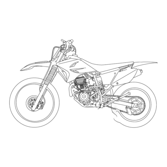
DESCRIPTION EAU10411 Left view 1. Fuel cock (page 4-5) 2. Starter (choke) knob (page 4-6) 3. Air filter element (page 7-10) 4. Shift pedal (page 4-2) -
Page 15: Right View
DESCRIPTION EAU10421 Right view 1. Fuse (page 7-27) 2. Battery (page 7-25) 3. Shock absorber assembly spring preload adjusting nut (page 4-7) 4. Engine oil filter element (page 7-7) 5. Brake pedal (page 4-3) -
Page 16: Controls And Instruments
DESCRIPTION EAU10431 Controls and instruments 1. Clutch lever (page 4-2) 2. Engine stop switch (page 4-1) 3. Start switch (page 4-1) 4. Brake lever (page 4-2) 5. Throttle grip (page 7-13) 6. Fuel tank cap (page 4-3) -
Page 17: Instrument And Control Functions
INSTRUMENT AND CONTROL FUNCTIONS EAUW1881 EAU1234H EAU12672 Ignition switch Handlebar switches Engine stop button “ENGINE STOP” Hold this button pushed until the en- Left gine stops in case of an emergency, such as when the vehicle overturns or when the throttle cable is stuck. EAU12713 Start switch “... -
Page 18: Clutch Lever
INSTRUMENT AND CONTROL FUNCTIONS EAU31641 EAU12872 EAU12892 Clutch lever Shift pedal Brake lever 1. Clutch lever 1. Shift pedal 1. Brake lever The clutch lever is located at the left The shift pedal is located on the left The brake lever is located on the right handlebar grip. -
Page 19: Brake Pedal
INSTRUMENT AND CONTROL FUNCTIONS EAU12944 EAU13183 EAU13213 Brake pedal Fuel tank cap Fuel Make sure there is sufficient gasoline in the tank. EWA10882 WARNING Gasoline and gasoline vapors are extremely flammable. To avoid fires and explosions and to reduce the risk of injury when refueling, follow these instructions. - Page 20 EWA15152 WARNING Your Yamaha engine has been de- Gasoline is poisonous and can signed to use regular unleaded gaso- cause injury or death. Handle gaso- line with a research octane number of line with care.
-
Page 21: Fuel Tank Breather Hose
INSTRUMENT AND CONTROL FUNCTIONS EAU13414 EAU13562 Fuel tank breather hose Fuel cock The fuel cock supplies fuel from the tank to the carburetor while filtering it also. The fuel cock has three positions: 1. Arrow mark positioned over “ON” 1. Fuel tank breather hose With the lever in this position, fuel flows Before operating the motorcycle: to the carburetor. -
Page 22: Starter (Choke) Knob
INSTRUMENT AND CONTROL FUNCTIONS This indicates reserve. If you run out of EAU13601 EAU13962 Starter (choke) knob “ ” Seat fuel while riding, move the lever to this position. Fill the tank at the first oppor- To remove the seat tunity. -
Page 23: Adjusting The Shock Absorber Assembly
INSTRUMENT AND CONTROL FUNCTIONS decrease the spring preload and EAUW2501 Adjusting the shock absorber thereby soften the suspension, assembly turn the adjusting nut in direction This shock absorber assembly is (b). equipped with a spring preload adjust- The spring preload setting is de- ing nut. -
Page 24: Sidestand
Do not dispose of a damaged or the locknut to the specified torque. worn-out shock absorber as- [ECA10122] sembly yourself. Take the shock Tightening torque: absorber assembly to a Yamaha Locknut: dealer for any service. 70 Nm (7.0 m·kgf, 51 ft·lbf) EWA10222 1. Sidestand WARNING... -
Page 25: Starting Circuit Cut-Off System
INSTRUMENT AND CONTROL FUNCTIONS EAUW0802 Starting circuit cut-off system The starting circuit cut-off system (comprising the clutch switch and the neutral switch) prevents starting when the transmission is in gear and the clutch lever is not pulled. Periodically check the operation of the starting circuit cut-off system accord- ing to the following procedure. - Page 26 INSTRUMENT AND CONTROL FUNCTIONS 4-10...
-
Page 27: For Your Safety - Pre-Operation Checks
• If necessary, add recommended oil to specified level. • Check vehicle for oil leakage. • Check operation. • If soft or spongy, have Yamaha dealer bleed hydraulic system. • Check lever free play. • Adjust if necessary. Front brake •... - Page 28 • Make sure that operation is smooth. • Check throttle grip free play. Throttle grip 7-13, 7-22 • If necessary, have Yamaha dealer adjust throttle grip free play and lubricate ca- ble and grip housing. • Make sure that operation is smooth. Control cables 7-22 •...
-
Page 29: Operation And Important Riding Points
6. After starting the engine, move the there is a control or function you do not system to enable starting, one of the starter (choke) back halfway. understand, ask your Yamaha dealer. following conditions must be met: 7. When the engine is warm, turn the EWA10272 ... -
Page 30: Starting A Warm Engine
OPERATION AND IMPORTANT RIDING POINTS EAU16641 EAU16673 ECA10261 Starting a warm engine Shifting NOTICE Follow the same procedure as for Even with the transmission in starting a cold engine with the excep- the neutral position, do not tion that the starter (choke) is not re- coast for long periods of time quired when the engine is warm. -
Page 31: Engine Break-In
To allow the engine If any engine trouble should occur to cool down from the temporary build- during the engine break-in period, up of heat, cruise at a lower engine immediately have a Yamaha dealer speed. check the vehicle. -
Page 32: Periodic Maintenance And Adjustment
From 7000 km (4200 mi) or 18 months, repeat the maintenance intervals starting from 3000 km (1800 mi) or 6 months. Items marked with an asterisk should be performed by a Yamaha dealer as they require special tools, data and tech- nical skills. - Page 33 PERIODIC MAINTENANCE AND ADJUSTMENT INITIAL ODOMETER READINGS 1000 km 3000 km 5000 km ITEM CHECKS AND MAINTENANCE JOBS (600 mi) or (1800 mi) or (3000 mi) or 1 month or 6 months or 12 months or 30 hours 90 hours 150 hours •...
-
Page 34: General Maintenance And Lubrication Chart
From 7000 km (4200 mi) or 18 months, repeat the maintenance intervals starting from 3000 km (1800 mi) or 6 months. Items marked with an asterisk should be performed by a Yamaha dealer as they require special tools, data and tech- nical skills. - Page 35 Swingarm pivot bearings • Moderately repack with lithium-soap-based grease. • Check chain slack/alignment and condition. Drive chain • Adjust and lubricate chain with Yamaha chain lubricant Every ride or other suitable chain lubricant thoroughly. • Check bearing assemblies for looseness.
- Page 36 150 hours √ √ • Check operation. Rear suspension link piv- 20 * √ • Lubricate with lithium-soap-based grease. • Apply Yamaha cable lubricant or other suitable cable lu- √ √ √ 21 * Control cables bricant thoroughly. • Check operation.
-
Page 37: Removing And Installing The Panel
Do not attempt to diagnose such problems EAU19211 Panel yourself. Instead, have a Yamaha deal- er check the vehicle. To remove the panel If the spark plug shows signs of elec- Remove the screws, and then take the trode erosion and excessive carbon or panel off. -
Page 38: Engine Oil And Oil Filter Element
PERIODIC MAINTENANCE AND ADJUSTMENT Before installing a spark plug, the EAUW0613 Engine oil and oil filter ele- spark plug gap should be measured If a torque wrench is not available ment with a wire thickness gauge and, if when installing a spark plug, a good The engine oil level should be checked necessary, adjusted to specification. - Page 39 PERIODIC MAINTENANCE AND ADJUSTMENT 4. Remove the engine oil filler bolt and drain bolt to drain the oil from the crankcase. NOTICE: When removing the engine oil drain bolt, the O-ring, compression spring, and oil strainer will fall out. Take care not to lose these parts.
- Page 40 PERIODIC MAINTENANCE AND ADJUSTMENT 9. Clean the oil filter element with Tightening torques: solvent, and then install it. Engine oil drain bolt: 43 Nm (4.3 m·kgf, 31 ft·lbf) Oil filter element drain bolt: Check the oil filter element for damage 10 Nm (1.0 m·kgf, 7.2 ft·lbf) and replace it if necessary.
-
Page 41: Cleaning The Air Filter Element
If no oil 2. Pull the air filter element out of the comes out after one minute, air filter case. turn the engine off immediately so it will not seize. If this occurs, have a Yamaha dealer repair the vehicle. 7-10... - Page 42 NOTICE: To avoid dam- [EWAW0022] Recommended oil: aging the foam material, handle Yamaha foam air filter oil or other it gently and carefully, and do quality foam air filter oil not twist or wring it. [ECA10512] 7.
-
Page 43: Adjusting The Carburetor
[ECA10482] to a Yamaha dealer, who has the nec- periodic maintenance and lubrication 9. Install the air filter case cover and essary professional knowledge and ex- chart. -
Page 44: Checking The Throttle Grip Free Play
(b). resulting in improper air-fuel mixture and/or engine noise. To prevent this from occurring, the valve clearance must be adjusted by a Yamaha dealer at the intervals specified in the periodic maintenance and lubrication chart. 1. Throttle grip free play 1. -
Page 45: Tires
Safety in all con- glass fragments in it, or if the sidewall ditions of riding depends on a relatively is cracked, have a Yamaha dealer re- Front: small area of road contact. Therefore, it 100 kPa (1.00 kgf/cm², 15 psi) place the tire immediately. -
Page 46: Spoke Wheels
To maximize the performance, durabil- ed below have been approved for this It is not recommended to patch ity, and safe operation of your motor- model by Yamaha Motor da Amazônia a punctured tube. If unavoid- cycle, note following points Ltda. -
Page 47: Adjusting The Clutch Lever Free Play
3. Locknut (clutch cable) brake lever end. If there is free play, 4. Adjusting nut adjusting nut in direction (a). To have a Yamaha dealer inspect the 5. Clutch lever free play decrease the clutch lever free brake system. play, turn the adjusting nut in di-... -
Page 48: Adjusting The Brake Pedal Height And Free Play
Brake pedal free play 1. Brake pedal position 2. Brake pedal free play EWA10671 WARNING It is advisable to have a Yamaha dealer make these adjustments. Brake pedal height The top of the brake pedal should be 1. Adjusting bolt positioned approximately 3.0 mm (0.12... -
Page 49: Checking The Front Brake Pads And Rear Brake Shoes
Yamaha the brake. If a brake pad has worn to dealer replace the brake shoes as a the point that a wear indicator almost set. -
Page 50: Checking The Brake Fluid Level
If the brake Use only the specified brake flu- fluid level goes down suddenly, have a id; otherwise, the rubber seals Yamaha dealer check the cause before may deteriorate, causing leak- further riding. age. Refill with the same type of brake fluid. -
Page 51: Changing The Brake Fluid
PERIODIC MAINTENANCE AND ADJUSTMENT EAU22724 EAU22762 Changing the brake fluid Drive chain slack Have a Yamaha dealer change the The drive chain slack should be brake fluid at the intervals specified in checked before each ride and adjusted the periodic maintenance and lubrica- if necessary. -
Page 52: Cleaning And Lubricating The Drive Chain
PERIODIC MAINTENANCE AND ADJUSTMENT er drive chain slack will over- EAU23026 Tightening torque: Cleaning and lubricating the load the engine as well as other Axle nut: drive chain vital parts of the motorcycle and 80 Nm (8.0 m·kgf, 58 ft·lbf) The drive chain must be cleaned and can lead to chain slippage or 5. -
Page 53: Checking And Lubricating The Cables
Yamaha dealer at the intervals cated if necessary. If a cable is specified in the periodic maintenance damaged or does not move smoothly, chart. -
Page 54: Checking And Lubricating The Brake Pedal
Recommended lubricants: WARNING Brake lever: If the sidestand does not move up Silicone grease and down smoothly, have a Yamaha Clutch lever: Lithium-soap-based grease dealer check or repair it. Otherwise, the sidestand could contact the ground and distract the operator, re- sulting in a possible loss of control. -
Page 55: Checking The Front Fork
WARNING! To avoid injury, of it falling over. have a Yamaha dealer check or re- [EWA10752] securely support the vehicle so 2. Hold the lower ends of the front pair it. -
Page 56: Checking The Wheel Bearings
If there is play in the wheel hub or if the wheel does not turn smoothly, have a Yamaha dealer check the wheel bearings. 1. Battery The battery is located behind panel. - Page 57 To charge the battery 2. If the battery will be stored for working near batteries. In case Have a Yamaha dealer charge the bat- more than two months, check it at of contact, administer the fol- tery as soon as possible if it seems to least once a month and fully lowing FIRST AID.
-
Page 58: Replacing The Fuse
4. If the fuse immediately blows nance requiring the motorcycle to again, have a Yamaha dealer stand upright. Check that the motorcy- check the electrical system. cle is in a stable and level position be- fore starting any maintenance. -
Page 59: Front Wheel
PERIODIC MAINTENANCE AND ADJUSTMENT a jack either under each side of the 4. Pull the wheel axle out, and then EAU24361 Front wheel remove the wheel. NOTICE: Do frame in front of the rear wheel or under each side of the swingarm. not apply the brake after the EAU56231 wheel and brake disc have been... -
Page 60: Rear Wheel
PERIODIC MAINTENANCE AND ADJUSTMENT 2. Remove the brake pedal free play EAU25081 Rear wheel adjusting nut, and then discon- The drive chain does not need to be nect the brake rod from the brake disassembled in order to remove and EAU56600 camshaft lever. -
Page 61: Troubleshooting
Axle nut: 80 Nm (8.0 m·kgf, 58 ft·lbf) self. However, should your motorcycle require any repair, take it to a Yamaha 6. Install the brake rod onto the dealer, whose skilled technicians have brake camshaft lever, and then in-... -
Page 62: Troubleshooting Chart
Remove the spark plug and check the electrodes. The engine does not start. Have a Yamaha dealer check the vehicle. Check the compression. 4. Compression The engine does not start. There is compression. -
Page 63: Motorcycle Care And Storage
MOTORCYCLE CARE AND STORAGE ucts onto seals, gaskets, sprock- detergent residue using plenty EAU41359 Care ets, the drive chain and wheel of water, as it is harmful to plas- While the open design of a motorcycle axles. Always rinse the dirt and tic parts. - Page 64 WARNING 2. Apply a corrosion protection spray on all metal, including chrome- Contaminants on the brakes or tires Consult a Yamaha dealer for advice on and nickel-plated, surfaces to pre- can cause loss of control. what products to use. Make sure that there is no oil or vent corrosion.
-
Page 65: Storage
MOTORCYCLE CARE AND STORAGE 2. For motorcycles equipped with a WARNING! To prevent dam- EAU26153 Storage fuel cock that has an “OFF” posi- age or injury from sparking, tion: Turn the fuel cock lever to make sure to ground the Short-term “OFF”. - Page 66 MOTORCYCLE CARE AND STORAGE cessively cold or warm place [less than 0 °C (30 °F) or more than 30 °C (90 °F)]. For more information on storing the battery, see page 7-25. Make any necessary repairs before storing the motorcycle.
-
Page 67: Specifications
SPECIFICATIONS Dimensions: Lubrication system: Clutch: Wet sump Overall length: Clutch type: Engine oil: 2065 mm (81.3 in) Wet, multiple-disc Overall width: Recommended brand: Transmission: 800 mm (31.5 in) YAMALUBE Primary reduction ratio: Overall height: Type: 3.318 (73/22) 1180 mm (46.5 in) SAE 10W-30, 10W-40, 10W-50, 15W-40, Final drive: Seat height:... - Page 68 SPECIFICATIONS Front tire: Front brake: Voltage, capacity: 12 V, 4.0 Ah Type: Type: Fuse: With tube Single disc brake Size: Operation: Fuse: 80/100-21 51R Right hand operation 10.0 A Manufacturer/model: Specified brake fluid: PIRELLI/MT320H DOT 4 Rear brake: Speed rating: 170 km/h (106 mph) Type: Rear tire:...
-
Page 69: Consumer Information
Record the vehicle identification num- ber and model label information in the spaces provided below for assistance when ordering spare parts from a Yamaha dealer or for reference in case the vehicle is stolen. VEHICLE IDENTIFICATION NUMBER: 1. Vehicle identification number 1. -
Page 70: Index
INDEX Fuel cock ..........4-5 Start switch ..........4-1 Fuel tank breather hose......4-5 Steering, checking ........7-24 Air filter element, cleaning ....7-10 Fuel tank cap.......... 4-3 Storage ...........8-3 Fuse, replacing ........7-27 Supporting the motorcycle ....7-27 Battery ..........7-25 Brake and clutch levers, checking and Handlebar switches........ - Page 71 JC - 2014...